Bluetti AC500/B300S hacking
Some videos of mine :
Using for home backup in UK
Review/teardown :
I've been messing around with this system to make it part of an automatic
solar
car charger.
One thing needed for this is to get it to tunrn on the AC output when State
of Charge (SoC) reaches a certain limit, and turn off at a lower limit.
I found some usful info on
https://diysolarforum.com/threads/monitoring-bluetti-systems.37870/
It can be controlled over Bluetooth or Wifi with the Bluetti App, but I'm
looking to control it directly, ultimately using an ESP32 based bluetooth
device, but for now I found that internally it uses RS485 to communicate between
the Bluetooth/Wifi board and the main unit, which is much easier to talk to, and
allows sniffing of the Bluetooth data to the Bluetti App.
This is the wifi/Bluetooth board -basically little more than an ESP32 module
with RS485 transceiver. Connector is a 3.81mm pluggable terminal block, same at
both ends of the cable.

This board acts as a master, periodically sending commands to the main AC500
board to retreive data. I believe the over-the-air protocol is basically the
same as the RS485 data, maybe with some wrapping. The AC500 is quite happy to
run with this board disconnected. The board lives under the top cover, and is a
pain to get to as it needs a lot of disassembly, including use of a hilariously
long allen key for the bolts holding the top & bottom case halves together.
Fortunately the RS485 connector on the main PCB can be accessed by removing only
the back cover (inc. 2 screws under each label)
 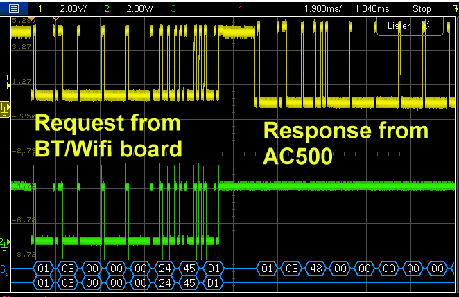
Connecting this to a PC RS485 interface allows for easier experimentation and
reverse-engineering, as well as sniffing the comms to the Bluetti App.
Comms are at 9600 baud,8N1. there is a 16 byte CRC but this doesn't need to be
known - commands can copy a fixed CRC sniffed from teh Bluetooth App, and it can
be ignored for received data
I reverse-enineered the protocol by sniffing commands from the Bluetooth App,
and observing returned data. most of the data is listed below
Output control commands :
AC On : 01 06 0B BF 00 01 7B CA
AC Off : 01 06 0B BF 00 00 BA 0A
DC On : 01 06 0B C0 00 01 4A 12
DC Off : 01 06 0B C0 00 00 8B D2
The Bluetti App uses five commands to retreive data. The spread of data over
the different sommands suggest this interface has had bits added on over time to
add features for newer models.
|
Responses to command 01 03 00 46 00
5A 24 24 (bold to identify command)
returns 185 bytes
|
|
Word offset, decimal, excludes initial 01, MSB first
|
|
|
00
|
03b4
|
Constant
|
|
01
|
|
0 : no AC out
1 ; AC out, battery supply.
2: AC in & out bypass
|
|
02
|
|
AC out volts * 10 (ups or bypass)
|
|
03
|
|
AC in or out to battery amps*10, unsigned (grid in minus ac out)
|
|
04
|
Signed
|
AC watts in & out, -ve for charge, +ve for discharge
|
|
05
|
5000 dec
|
AC Watts max constant ( maybe temp/SoC dependent?), 0 if AC off
|
|
06
|
|
AC Amps out*10
|
|
07
|
|
AC watts out
|
|
08
|
|
AC Volts in *10
|
|
09
|
|
AC Amps in *10
|
|
10
|
|
AC watts in
|
|
11
|
|
AC in frequency * 100
|
|
12
|
|
1 if AC in present
|
|
13
|
|
|
|
14
|
|
12V DC volts*10 ?
|
|
15
|
|
12v DC load amps*10
|
|
16
|
|
DC load W total
|
|
17
|
03 60
|
PV1 in volts|*10
|
|
18
|
02f7
|
PV1 in watts
|
|
19
|
0058
|
PV1 in amps*10
|
|
20
|
260
|
Varies slightly - temperature maybe? Deg.c*10 ?
|
|
21
|
0
|
?constant
|
|
22
|
0006
|
?constant
|
|
23
|
534
|
Battery voltage *10
|
|
24
|
013f
|
Battery charge/discharge current, unsigned
|
|
25
|
002d
|
State of charge %
|
|
26
|
60
|
?
|
|
27
|
1
|
|
|
28
|
0
|
|
|
29
|
900
|
900 when dc1 or dc2 input active, else 0
|
|
30
|
5760
|
?constant
|
|
31
|
1200
|
?constant
|
|
28-32
|
|
All 00
|
|
33
|
0x258/600
|
|
|
34
|
0x1680/5760
|
|
|
35
|
0x4b0/1200
|
|
|
36-51
|
|
16x Cell voltages, /10mV
|
|
|
|
|
|
Responses to command 01 03 0B B8 00 52 46 36
|
|
Word offset, excluding initial 01
|
Hex/dec
|
|
|
|
|
|
|
|
|
|
|
|
|
|
|
|
0
|
0x03a4 / 932
|
|
|
1
|
|
|
|
2
|
|
1 : customised UPS
2 : PV priority UPS
3 : standard UPS
4 : time control UPS
|
|
8
|
|
0/1 AC off/on
|
|
|
|
0/1 DC off/on
|
|
16
|
0x1e/30
|
|
|
17
|
0x64 / 100
|
|
|
|
|
|
|
20
|
0x01/10
|
AC max Charge current, amps
|
|
|
|
|
|
26
|
7
|
|
|
28
|
7
|
|
|
30
|
9
|
|
|
32
|
180A
|
Year:month ( 2024:Oct)
|
|
33
|
0711
|
Day:hour ( 7th, 17xx )
|
|
34
|
0x060f
|
Mins:secs ( 6:15)
|
|
|
|
|
|
40
|
1
|
|
|
42
|
0x700 / 1792
|
|
|
43
|
2
|
|
|
44
|
0x0700/1792
|
|
|
45
|
0x0900/2304
|
|
|
46
|
2
|
|
|
47
|
0x1100/4532
|
|
|
48
|
0x1600 / 5632
|
|
|
49
|
1
|
|
|
50
|
0x1700/5888
|
|
|
51
|
0x173b/5947
|
|
|
52
|
2
|
|
|
62
|
|
Sleep time 2-5 = 30s/1min/5min/never
|
|
|
|
|
|
64
|
|
0/1 : ECO off/on
|
|
|
|
|
|
67
|
|
0/1 power lifting mode off/on
|
|
|
|
|
|
Command 01 03 00 A0 00 2E c5 f4
returns 97 bytes
|
|
0
|
0x035C
|
|
|
1
|
2
|
|
|
4
|
|
DC1 in volts*10
|
|
6
|
|
DC1 in watts
|
|
11
|
|
DC2 in volts*10
|
|
13
|
|
DC2 in watts
|
|
30
|
|
0/1 Bluetooth Off/on
|
|
31
|
|
0/1 Wifi off/on
|
|
|
|
|
|
Command 01 03 00 24 00 22 85 D8
returns 73 bytes
|
|
0
|
|
|
|
1
|
|
|
|
2
|
|
AC power in
|
|
3
|
|
AC power out
|
|
4
|
|
|
|
5
|
|
|
|
6
|
261
|
?temp – varies slightly
|
|
7
|
|
|
|
8
|
|
SoC %
|
|
9
|
1
|
|
|
10
|
|
1 when grid on
|
|
11
|
|
|
|
12
|
|
1 when grid on
|
|
13
|
|
0/1 : AC out off/on
|
|
14
|
|
0/1 : DC out off/on
|
|
|
|
|
|
Response to Command 01 03 00 00 00
24 45 d10
|
|
0
|
0x348
|
|
|
11
|
0x4143
|
“AC” model number
|
|
12
|
0x3530
|
“50”
|
|
13
|
0x3000
|
“0”
|
|
17
|
0x3FD /1021
|
Probably serial number etc. AC5002232000027956
|
|
18
|
0x9D34
|
|
|
19
|
0xAD91
|
|
|
20
|
0x207
|
|
|
24
|
0x2D44
|
|
|
25
|
6
|
|
|
26
|
0x2CFA
|
|
|
27
|
6
|
|
|
28
|
0x8F40
|
|
|
29
|
1
|
|
|
|
|
|
|
|
|
|
|