SlideShare a Scribd company logo
3
Most read
5
Most read
6
Most read
1
Department Of Electrical Engineering
INSTRUMENTATION & MEASURMENTATION(LAB)
OBSTACLE AVOIDING ROBOT
Group Members
Aisha Naeem Khan 02-133182-075
Moosa Naeem Khan 02-133182-074
BEE-7C
FALL 2021
Submitted to
Engr. Ayesha Waris
2
Table of Contents
1. Abstract.................................................................................................................3
2. Introduction..........................................................................................................3
3. Literature Review................................................................................................ 4
4. Components and Tools Description....................................................................5
5. Block Diagram/Flow Chart.................................................................................6
6. Methodology......................................................................................................... 6
6.1. ProposedModel………………………………………………………6
6.2 Circuit/ Simulation Diagram......................................................…...7
6.3 Code and Description……………………………………..10
7. Results and Discussions..................................................................................... 11
8. Conclusion and Future Work........................................................................... 11
9. Project Summary............................................................................................... 11
10. Project Pictures.................................................................................................. 12
11. References...........................................................................................................12
3
1. ABSTRACT
We are designing an obstacle avoiding robot that will change trajectory when it senses
objects in its path.
The results of the distance calculation used to control the movement of the robot, hanse
the robot is able to avoid unknown obstacles. This obstacle robot divided into 3 parts,
namely Arduino Uno as a controller, L298N driver as a motor/wheel controller and
ultrasonic sensor(s) HC-SR04 as a sending and receiving device for ultrasonic signals.
The ultrasonic sensor design on the obstacle robot placed at the front of the robot with
the obstacle position in front. From the data analysis, the obstacle robot can determine
the accuracy level of the detected distance and can stop according to the detected
obstacle distance.
The test results show that the obstacle robot is less accurate in detecting the obstacles
in front of it, as evidenced by the test results that there is an average error of 0.118.
However there are still many applications for the work done that can be used in
vaccums , goombas(cleaners), self driving cars etc.
2. INTRODUCTION
A Robot is a set of mechanical devices that can perform physical tasks, either human
supervision and control, or using predefined programs. The robot that is the topic of
this research is a type of obstacle robot or in other words a robot that can move from
place to place. Obstacle robots are robotic constructions whose characteristics are
having actuators in the form of wheels to move the entire robot body, so that the robot
can move positions from one point to another.
In this work, we have presented a robot,which is compact, autonomous and fully
functional.This robot/smartcar is built to sense any obstacle in its path, to avoid it and
resume its running involving the pre-computation of an obstacle free path.Ultrasonic
sensors were adapted to implement a real-time obstacle avoidance system for wheeled
robots, so that the robot can continually detect surroundings,avoid obstacles, and move
toward the target area. Of course we have not given it a predefined path , which makes
things considerably easier to implement.
We use an Arduino UNO with a Motor Shield along with Stepper Motors to make the
car, and for sensing we incorporate an Ultrasonic Sensor which accurately and
4
efficiently detects any obstacles in the robot’s path. The Arduino is coded such that the
robot moves backward when an obstacle arises in front of it with a maximum limit of
50cms in ideal testing conditions.
Throughout the construction of this model, we educated ourselves to the Arduino
coding language, the Motor Shield functionality, and comprehensively, with the
working of an ultrasonic sensor and its features.
3. LITERATURE REVIEW
From the industrial side, robots have achieved great success, such as manipulator
robots, humanoid robots, and android robots that used by large companies. But
despite all the success that has been achieved, this robotic robot has one fundamental
drawback, namely limited mobility, therefore obstacle robots are present and able to
travel around the entire automotive company without using a steering wheel,
performing their abilities wherever as effectively as possible.
The application of ultrasonic signals has been widely carried out, especially in the
robot industry. The following are some previous studies in the application of ultrasonic
signals:
In the thesis entitled "Design of a Fire Extinguishing Car Robot Based on the
ATmega 252 Microcontroller", which discusses the use of light sensors and ultrasonic
sensors in controlling car robots for the purpose of finding points. fire and extinguish it;
5
In the thesis entitled "Design of a Moving Object Tracking Car Robot Based on PA
(Proportional - Derivative) Controller Using the ATmega 8535 Microcontroller".
which uses fuzzy- PID logic and ultrasonic sensors to chart a path for itself.
Inspired by this, this research will develop a obstacle robot that controlled using
Arduino Uno as its control, L298N driver as a motor controller and ultrasonic sensor
HC-SR04 as a distance sensor to detect the distance to the surrounding obstructions.
The results of the distance reading will used as information to control the movement of
the robot obstacle such as stopping based on the distance of the detected obstacle
4. COMPONENTS AND TOOLS DESCRIPTION
We are using :
4.1. Batteries
9Vs approx for both motor and arduino
4.2. Chasis
For mounting wheels, arduino and other components on.
4.3. L298N H-brige motor driver .
Its IC consists of logical transistors (TTL) with NAND gates that function to make
it easier to determine the direction of rotation of a dc motor or stepper motor. The
advantage of this L298N motor driver module is in terms of precision in controlling
the motor so that the motor is easier to control.
4.4. Arduino UNO
Which is our microcontroller of choice here as it is open source and
easy to use.
4.5. Sensor HC-SR04
The HC-SR04 is an ultrasonic sensor that used to measure the
distance between an obstacle and the sensor.The U
ng it takes for the echo of the sound to reflect back
4.6. Motors & castor wheel
They are of 5Vs and are the wheels running this operation.
6
5. BLOCK / FLOW DIAGRAM
6. METHODOLOGY
6.1. Proposed Model/Circuit
The proposed model has 3
sensors mounted at the front.
7
6.2. Code
int trigPin1 = 3; // Trigger
int echoPin1 = 4; // Echo
int trigPin2 = 12; // Trigger
int echoPin2 = 13; // Echo
int trigPin3 = A0; // Trigger
int echoPin3 = A1; // Echo
int revleft4 = 10; // Motor Pins
int fwdleft5 =11; // High
int revright6 = 8;
int fwdright7 = 9; // High
int enright = 6;
int enleft = 5;
long duration, cm, inches,duration2,
cm2,duration3, cm3;
void setup() {
//Serial Port begin
Serial.begin (9600);
//Define inputs and outputs
pinMode(trigPin1, OUTPUT);
pinMode(echoPin1, INPUT);
pinMode(trigPin2, OUTPUT);
pinMode(echoPin2, INPUT);
pinMode(trigPin3, OUTPUT);
pinMode(echoPin3, INPUT);
pinMode(revleft4, OUTPUT); // Set
Motor Pins As O/P
pinMode(fwdleft5, OUTPUT);
pinMode(revright6, OUTPUT);
pinMode(fwdright7, OUTPUT);
pinMode(enright, OUTPUT);
pinMode(enleft, OUTPUT);
}
void loop() {
// The sensor is triggered by a HIGH
pulse of 10 or more microseconds.
// Give a short LOW pulse beforehand
to ensure a clean HIGH pulse:
digitalWrite(trigPin1, LOW);
delayMicroseconds(5);
digitalWrite(trigPin1, HIGH);
delayMicroseconds(10);
digitalWrite(trigPin1, LOW);
// Read the signal from the sensors: a
HIGH pulse whose
// duration is the time (in microseconds)
from the sending
// of the ping to the reception of its
echo off of an object.
pinMode(echoPin1, INPUT);
duration = pulseIn(echoPin1, HIGH);
// Convert the time into a distance
cm = (duration/2) / 29.1; // Divide by
29.1 or multiply by 0.0343
inches = (duration/2) / 74; // Divide
by 74 or multiply by 0.0135
delay(50);
if (cm > 20) // Condition For Absence
Of Obstacle
{
digitalWrite(fwdright7, HIGH); //
Move Forward
8
digitalWrite(revright6, LOW);
digitalWrite(fwdleft5, HIGH);
digitalWrite(revleft4, LOW);
analogWrite(enright,135); // Run in
half speed
analogWrite(enleft, 135); // Run in
half speed
}
if (cm < 20) // Condition For Presence
Of Obstacle
{
digitalWrite(fwdright7, LOW); //Stop
digitalWrite(revright6, LOW);
digitalWrite(fwdleft5, LOW);
digitalWrite(revleft4, LOW);
delay(500);
digitalWrite(fwdright7, LOW); //
Move Backward
digitalWrite(revright6, HIGH);
digitalWrite(fwdleft5, LOW);
digitalWrite(revleft4, HIGH);
delay(500);
digitalWrite(fwdright7, LOW); //Stop
digitalWrite(revright6, LOW);
digitalWrite(fwdleft5, LOW);
digitalWrite(revleft4, LOW);
delay(100);
checkLeftDistance();
delay(20);
checkRightDistance();
delay(20);
if (cm2 > cm3)
{
digitalWrite(fwdright7, HIGH); //
Move Left
digitalWrite(revright6, LOW);
digitalWrite(revleft4, LOW);
digitalWrite(fwdleft5, LOW);
}
else if (cm3 > cm2 )
{
digitalWrite(fwdright7, LOW); //
Move Right
digitalWrite(revright6, LOW);
digitalWrite(revleft4, HIGH);
digitalWrite(fwdleft5, LOW);
}
else
{
digitalWrite(fwdright7, HIGH); //
Move Left
digitalWrite(revright6, LOW);
digitalWrite(revleft4, LOW);
digitalWrite(fwdleft5, LOW);
}
delay(500);
}
}
void checkLeftDistance()
{
digitalWrite(trigPin2, LOW);
delayMicroseconds(4);
digitalWrite(trigPin2, HIGH);
delayMicroseconds(10);
digitalWrite(trigPin2, LOW);
duration2 = pulseIn(echoPin2, HIGH);
cm2 = (duration2/2) / 29.1;
Serial.print("Left distance: ");
9
Serial.print(cm2);
Serial.println(" cm");
}
void checkRightDistance()
{
digitalWrite(trigPin3, LOW);
delayMicroseconds(4);
digitalWrite(trigPin3, HIGH);
delayMicroseconds(10);
digitalWrite(trigPin3, LOW);
duration3 = pulseIn(echoPin3, HIGH);
cm3 = (duration3/2) / 29.1;
Serial.print("Right distance: ");
Serial.print(cm3);
Serial.println(" cm");
}
[/code]
10
6.3. Code/Circuit Description
The robot is switched on by giving it 9V DC power from an external battery.The
motors starts rotating and thus the robot starts moving forward.
However we need to know how the ultrasonic sensor work to explain further.
The ultrasonic sensor uses sonar to determine the distance to an object. What
happens it that:
 The ultrasound transmitter (trig pin) emits a high-frequency sound (40 kHz).
 The sound travels through the air. If it finds an object, it bounces back to the module.
 The ultrasound receiver (echo pin) receives the reflected sound (echo).
The time between the transmission and reception of the signal allows us to
calculate the distance to an object. This is possible because we know the sound’s
velocity in the air. The formula:
distance to an object = ((speed of sound in the air)*time)/2
During this time, the center ultrasonic sensor keeps checking to see if anything is in
front of it.
So we can now explain that the central ulltrasonic sensor keeps checking to see if
anything is in front of it within a 20cm distance. If there isnt, it will keep going in a
straight line.
However, if there is something in front of it, the robot will stop and back up a little,
as the sensor senses distance less than 20cm. It will then use the sensors to the left
11
and the right and calculate where there is more distance from an object. And it
move in that direction.
This code will keep running in a loop.
7. RESULTS AND DISCUSSIONS
As we have seen, the robot will detect obstacles and change its trajectory accordingly.
It will sense with ultrasonic sensors if anything is in front within 20 cm of it and
change direction accordingly. There is an error margin in the ultrasonic sensor.
It will send maximum distance if object in question is touching it i.e. 0cm.
However the robot still works well enough and demonstrates the concept of obstacle
avoidance well.
8. CONCLUSION AND FUTURE WORK
This technique can also be used as a vision belt for blind people by changing the
ultrasonic sensor by a kinetic sensor ,which is a type of microwave sensor whose
sensing range is very high and the output of this sensor vary in according to the object
position changes. This technique enables blind people to navigate obstacles easily by
placing three vibratos in left, right and the centre of a belt named as Vision Belt.
On top of obstacle avoiding robot temperature/ pressure sensors can be added to
monitor the atmospheric conditions around. This is useful in places where the
environment is not suitable for humans. Same technology can be used in various
applications by modifying the program for example Line / Path finder Robot ,
automatic vacuum cleaner etc.
They can be used as services robots, for the Low Cost Obstacle Avoidance Robot,
purpose of household work and so many other indoor applications.
9. PROJECT SUMMARY
The goal of our project is to create an autonomous robot which intelligently detects any
obstacle in its path and navigates it according the actions we set for it.
12
10. PROJECT PICTURES
11. REFERENCES
https://www.ncbi.nlm.nih.gov/pmc/articles/PMC8545591/
https://ieeexplore.ieee.org/abstract/document/8570477
https://www.academia.edu/35334413/Obstacle_Avoiding_Smartcar_using_Arduino_an
d_Ultrasonic_Sensors_J_Component_Report
https://randomnerdtutorials.com/complete-guide-for-ultrasonic-sensor-hc-sr04/
https://forum.arduino.cc/t/digital-pin-0-and-1/475928/7
https://hardwarefun.com/tutorials/controlling-speed-of-dc-motors-using-arduino
https://www.researchgate.net/publication/356808148_Ultrasonic_Signal_Implementati
on_in_Arduino-Based_Obstacle_Robot_Control_System
https://www.slideshare.net/shubhamthakur614/final-report-obstacle-avoiding-roboat
https://hardwarefun.com/tutorials/controlling-speed-of-dc-motors-using-arduino

More Related Content

What's hot (20)

PPTX
Obstacle Avoidance Robotic Vehicle
Edgefxkits & Solutions
 
PPTX
Obstacle Avoidance ROBOT using ARDUINO
jovin Richard
 
DOCX
Obstacle avoiding robot.doc
Electronics - Embedded System
 
DOCX
Obstacle Avoiding Robot Report Robot23
Abhijeet kapse
 
PPTX
Robo wireless controll
Sumit Saini
 
PPTX
OBSTACLE AVOIDING CAR
Shubham Thakur
 
PPTX
Obstacle avoiding Robot
Rasheed Khan
 
PPTX
Obstacle avoidance robot
Rahuldey1991
 
DOC
Obstacle avoiding robot(Lab report)
Захір Райхан
 
PPTX
Obstacle Avoidance Robot
Ratan Srikanth
 
DOCX
Gesture Controlled Car_Project report
Ashikapokiya12345
 
PPTX
Traffic light controller
Rkrishna Mishra
 
PPTX
Obstacle detection Robot using Ultrasonic Sensor and Arduino UNO
Sanjay Kumar
 
DOCX
Wireless E-Notice Board Using Bluetooth Report.docx
AbhishekGM10
 
PPT
up date IOT-Fire-Fighting-Robot-Ppt-1.ppt
RakibulHassan77
 
PPTX
Password based door locking system
Arjun Singh
 
PPT
Automatic vehicle accident detection and messaging system using gsm and gps m...
mahesh_rman
 
PPTX
ACCIDENT REPORTING SYSTEM USING MEMS
Rohit Sinha
 
PPTX
Obstacle Avoidance Robot Summer training Presentation
Wasi Abbas
 
PDF
Obstacle detection using ultra sonic sensor
satyashanker
 
Obstacle Avoidance Robotic Vehicle
Edgefxkits & Solutions
 
Obstacle Avoidance ROBOT using ARDUINO
jovin Richard
 
Obstacle avoiding robot.doc
Electronics - Embedded System
 
Obstacle Avoiding Robot Report Robot23
Abhijeet kapse
 
Robo wireless controll
Sumit Saini
 
OBSTACLE AVOIDING CAR
Shubham Thakur
 
Obstacle avoiding Robot
Rasheed Khan
 
Obstacle avoidance robot
Rahuldey1991
 
Obstacle avoiding robot(Lab report)
Захір Райхан
 
Obstacle Avoidance Robot
Ratan Srikanth
 
Gesture Controlled Car_Project report
Ashikapokiya12345
 
Traffic light controller
Rkrishna Mishra
 
Obstacle detection Robot using Ultrasonic Sensor and Arduino UNO
Sanjay Kumar
 
Wireless E-Notice Board Using Bluetooth Report.docx
AbhishekGM10
 
up date IOT-Fire-Fighting-Robot-Ppt-1.ppt
RakibulHassan77
 
Password based door locking system
Arjun Singh
 
Automatic vehicle accident detection and messaging system using gsm and gps m...
mahesh_rman
 
ACCIDENT REPORTING SYSTEM USING MEMS
Rohit Sinha
 
Obstacle Avoidance Robot Summer training Presentation
Wasi Abbas
 
Obstacle detection using ultra sonic sensor
satyashanker
 

Similar to obstacle avoiding robot project (20)

PDF
Autonomous navigation robot
IRJET Journal
 
PDF
A presentation on obstacle avoiding robot
kantankit4
 
PPTX
Self Obstacle Avoiding Rover
Emam Hasan
 
PDF
Arduino_Project_Report
Jacob McCormick
 
DOCX
Final_Technical_Report_KevinHuang
Kevin Huang
 
DOCX
pdf-obstacle-avoiding-robot.docx
maheshwaran79
 
PDF
Developing Infrared Controlled Automated Door System
IJMER
 
DOCX
Automatic Collision Control System
Sankhadeep Rakshit
 
PPTX
BATCH 28 PHASE 3.pptx
ZuberAhmedV
 
PPTX
Project PPT.pptx
SamiullaPatel1
 
PDF
A SMART VOICE CONTROLLED PICK AND PLACE ROBOT.pdf
Aakash Sheelvant
 
PDF
A SMART VOICE CONTROLLED PICK AND PLACE ROBOT
IRJET Journal
 
PPTX
PC-based mobile robot navigation sytem
ANKIT SURATI
 
PPTX
371275588.pptx
AnandVerma529372
 
PDF
IRJET- Unmanned Ground Vehicle for Military Assistance
IRJET Journal
 
PPTX
Collision detector and avoidance robot
WaqarAhmad444
 
PDF
Ball following Robot using ESP32-cam & Arduino UNO
IRJET Journal
 
PPTX
ULTRA SONIC BASED NEVER FALLING ROBOT
bharath405
 
PDF
IRJET - The Line Follower -and- Pick and Place Robot
IRJET Journal
 
PDF
IRJET- Design and Development of Gesture Controlled Robot
IRJET Journal
 
Autonomous navigation robot
IRJET Journal
 
A presentation on obstacle avoiding robot
kantankit4
 
Self Obstacle Avoiding Rover
Emam Hasan
 
Arduino_Project_Report
Jacob McCormick
 
Final_Technical_Report_KevinHuang
Kevin Huang
 
pdf-obstacle-avoiding-robot.docx
maheshwaran79
 
Developing Infrared Controlled Automated Door System
IJMER
 
Automatic Collision Control System
Sankhadeep Rakshit
 
BATCH 28 PHASE 3.pptx
ZuberAhmedV
 
Project PPT.pptx
SamiullaPatel1
 
A SMART VOICE CONTROLLED PICK AND PLACE ROBOT.pdf
Aakash Sheelvant
 
A SMART VOICE CONTROLLED PICK AND PLACE ROBOT
IRJET Journal
 
PC-based mobile robot navigation sytem
ANKIT SURATI
 
371275588.pptx
AnandVerma529372
 
IRJET- Unmanned Ground Vehicle for Military Assistance
IRJET Journal
 
Collision detector and avoidance robot
WaqarAhmad444
 
Ball following Robot using ESP32-cam & Arduino UNO
IRJET Journal
 
ULTRA SONIC BASED NEVER FALLING ROBOT
bharath405
 
IRJET - The Line Follower -and- Pick and Place Robot
IRJET Journal
 
IRJET- Design and Development of Gesture Controlled Robot
IRJET Journal
 
Ad

Recently uploaded (20)

PPTX
Damage of stability of a ship and how its change .pptx
ehamadulhaque
 
PDF
Electrical Engineer operation Supervisor
ssaruntatapower143
 
PPTX
Worm gear strength and wear calculation as per standard VB Bhandari Databook.
shahveer210504
 
PPTX
fatigue in aircraft structures-221113192308-0ad6dc8c.pptx
aviatecofficial
 
PPTX
Solar Thermal Energy System Seminar.pptx
Gpc Purapuza
 
PDF
Viol_Alessandro_Presentazione_prelaurea.pdf
dsecqyvhbowrzxshhf
 
PPTX
Product Development & DevelopmentLecture02.pptx
zeeshanwazir2
 
PPTX
The Role of Information Technology in Environmental Protectio....pptx
nallamillisriram
 
PPTX
Evaluation and thermal analysis of shell and tube heat exchanger as per requi...
shahveer210504
 
PDF
Halide Perovskites’ Multifunctional Properties: Coordination Engineering, Coo...
TaameBerhe2
 
PDF
smart lot access control system with eye
rasabzahra
 
PPTX
Shinkawa Proposal to meet Vibration API670.pptx
AchmadBashori2
 
PPTX
VITEEE 2026 Exam Details , Important Dates
SonaliSingh127098
 
PPTX
美国电子版毕业证南卡罗莱纳大学上州分校水印成绩单USC学费发票定做学位证书编号怎么查
Taqyea
 
DOCX
CS-802 (A) BDH Lab manual IPS Academy Indore
thegodhimself05
 
PDF
International Journal of Information Technology Convergence and services (IJI...
ijitcsjournal4
 
PDF
Zilliz Cloud Demo for performance and scale
Zilliz
 
PPTX
265587293-NFPA 101 Life safety code-PPT-1.pptx
chandermwason
 
PDF
PORTFOLIO Golam Kibria Khan — architect with a passion for thoughtful design...
MasumKhan59
 
PPTX
Thermal runway and thermal stability.pptx
godow93766
 
Damage of stability of a ship and how its change .pptx
ehamadulhaque
 
Electrical Engineer operation Supervisor
ssaruntatapower143
 
Worm gear strength and wear calculation as per standard VB Bhandari Databook.
shahveer210504
 
fatigue in aircraft structures-221113192308-0ad6dc8c.pptx
aviatecofficial
 
Solar Thermal Energy System Seminar.pptx
Gpc Purapuza
 
Viol_Alessandro_Presentazione_prelaurea.pdf
dsecqyvhbowrzxshhf
 
Product Development & DevelopmentLecture02.pptx
zeeshanwazir2
 
The Role of Information Technology in Environmental Protectio....pptx
nallamillisriram
 
Evaluation and thermal analysis of shell and tube heat exchanger as per requi...
shahveer210504
 
Halide Perovskites’ Multifunctional Properties: Coordination Engineering, Coo...
TaameBerhe2
 
smart lot access control system with eye
rasabzahra
 
Shinkawa Proposal to meet Vibration API670.pptx
AchmadBashori2
 
VITEEE 2026 Exam Details , Important Dates
SonaliSingh127098
 
美国电子版毕业证南卡罗莱纳大学上州分校水印成绩单USC学费发票定做学位证书编号怎么查
Taqyea
 
CS-802 (A) BDH Lab manual IPS Academy Indore
thegodhimself05
 
International Journal of Information Technology Convergence and services (IJI...
ijitcsjournal4
 
Zilliz Cloud Demo for performance and scale
Zilliz
 
265587293-NFPA 101 Life safety code-PPT-1.pptx
chandermwason
 
PORTFOLIO Golam Kibria Khan — architect with a passion for thoughtful design...
MasumKhan59
 
Thermal runway and thermal stability.pptx
godow93766
 
Ad

obstacle avoiding robot project

  • 1. 1 Department Of Electrical Engineering INSTRUMENTATION & MEASURMENTATION(LAB) OBSTACLE AVOIDING ROBOT Group Members Aisha Naeem Khan 02-133182-075 Moosa Naeem Khan 02-133182-074 BEE-7C FALL 2021 Submitted to Engr. Ayesha Waris
  • 2. 2 Table of Contents 1. Abstract.................................................................................................................3 2. Introduction..........................................................................................................3 3. Literature Review................................................................................................ 4 4. Components and Tools Description....................................................................5 5. Block Diagram/Flow Chart.................................................................................6 6. Methodology......................................................................................................... 6 6.1. ProposedModel………………………………………………………6 6.2 Circuit/ Simulation Diagram......................................................…...7 6.3 Code and Description……………………………………..10 7. Results and Discussions..................................................................................... 11 8. Conclusion and Future Work........................................................................... 11 9. Project Summary............................................................................................... 11 10. Project Pictures.................................................................................................. 12 11. References...........................................................................................................12
  • 3. 3 1. ABSTRACT We are designing an obstacle avoiding robot that will change trajectory when it senses objects in its path. The results of the distance calculation used to control the movement of the robot, hanse the robot is able to avoid unknown obstacles. This obstacle robot divided into 3 parts, namely Arduino Uno as a controller, L298N driver as a motor/wheel controller and ultrasonic sensor(s) HC-SR04 as a sending and receiving device for ultrasonic signals. The ultrasonic sensor design on the obstacle robot placed at the front of the robot with the obstacle position in front. From the data analysis, the obstacle robot can determine the accuracy level of the detected distance and can stop according to the detected obstacle distance. The test results show that the obstacle robot is less accurate in detecting the obstacles in front of it, as evidenced by the test results that there is an average error of 0.118. However there are still many applications for the work done that can be used in vaccums , goombas(cleaners), self driving cars etc. 2. INTRODUCTION A Robot is a set of mechanical devices that can perform physical tasks, either human supervision and control, or using predefined programs. The robot that is the topic of this research is a type of obstacle robot or in other words a robot that can move from place to place. Obstacle robots are robotic constructions whose characteristics are having actuators in the form of wheels to move the entire robot body, so that the robot can move positions from one point to another. In this work, we have presented a robot,which is compact, autonomous and fully functional.This robot/smartcar is built to sense any obstacle in its path, to avoid it and resume its running involving the pre-computation of an obstacle free path.Ultrasonic sensors were adapted to implement a real-time obstacle avoidance system for wheeled robots, so that the robot can continually detect surroundings,avoid obstacles, and move toward the target area. Of course we have not given it a predefined path , which makes things considerably easier to implement. We use an Arduino UNO with a Motor Shield along with Stepper Motors to make the car, and for sensing we incorporate an Ultrasonic Sensor which accurately and
  • 4. 4 efficiently detects any obstacles in the robot’s path. The Arduino is coded such that the robot moves backward when an obstacle arises in front of it with a maximum limit of 50cms in ideal testing conditions. Throughout the construction of this model, we educated ourselves to the Arduino coding language, the Motor Shield functionality, and comprehensively, with the working of an ultrasonic sensor and its features. 3. LITERATURE REVIEW From the industrial side, robots have achieved great success, such as manipulator robots, humanoid robots, and android robots that used by large companies. But despite all the success that has been achieved, this robotic robot has one fundamental drawback, namely limited mobility, therefore obstacle robots are present and able to travel around the entire automotive company without using a steering wheel, performing their abilities wherever as effectively as possible. The application of ultrasonic signals has been widely carried out, especially in the robot industry. The following are some previous studies in the application of ultrasonic signals: In the thesis entitled "Design of a Fire Extinguishing Car Robot Based on the ATmega 252 Microcontroller", which discusses the use of light sensors and ultrasonic sensors in controlling car robots for the purpose of finding points. fire and extinguish it;
  • 5. 5 In the thesis entitled "Design of a Moving Object Tracking Car Robot Based on PA (Proportional - Derivative) Controller Using the ATmega 8535 Microcontroller". which uses fuzzy- PID logic and ultrasonic sensors to chart a path for itself. Inspired by this, this research will develop a obstacle robot that controlled using Arduino Uno as its control, L298N driver as a motor controller and ultrasonic sensor HC-SR04 as a distance sensor to detect the distance to the surrounding obstructions. The results of the distance reading will used as information to control the movement of the robot obstacle such as stopping based on the distance of the detected obstacle 4. COMPONENTS AND TOOLS DESCRIPTION We are using : 4.1. Batteries 9Vs approx for both motor and arduino 4.2. Chasis For mounting wheels, arduino and other components on. 4.3. L298N H-brige motor driver . Its IC consists of logical transistors (TTL) with NAND gates that function to make it easier to determine the direction of rotation of a dc motor or stepper motor. The advantage of this L298N motor driver module is in terms of precision in controlling the motor so that the motor is easier to control. 4.4. Arduino UNO Which is our microcontroller of choice here as it is open source and easy to use. 4.5. Sensor HC-SR04 The HC-SR04 is an ultrasonic sensor that used to measure the distance between an obstacle and the sensor.The U ng it takes for the echo of the sound to reflect back 4.6. Motors & castor wheel They are of 5Vs and are the wheels running this operation.
  • 6. 6 5. BLOCK / FLOW DIAGRAM 6. METHODOLOGY 6.1. Proposed Model/Circuit The proposed model has 3 sensors mounted at the front.
  • 7. 7 6.2. Code int trigPin1 = 3; // Trigger int echoPin1 = 4; // Echo int trigPin2 = 12; // Trigger int echoPin2 = 13; // Echo int trigPin3 = A0; // Trigger int echoPin3 = A1; // Echo int revleft4 = 10; // Motor Pins int fwdleft5 =11; // High int revright6 = 8; int fwdright7 = 9; // High int enright = 6; int enleft = 5; long duration, cm, inches,duration2, cm2,duration3, cm3; void setup() { //Serial Port begin Serial.begin (9600); //Define inputs and outputs pinMode(trigPin1, OUTPUT); pinMode(echoPin1, INPUT); pinMode(trigPin2, OUTPUT); pinMode(echoPin2, INPUT); pinMode(trigPin3, OUTPUT); pinMode(echoPin3, INPUT); pinMode(revleft4, OUTPUT); // Set Motor Pins As O/P pinMode(fwdleft5, OUTPUT); pinMode(revright6, OUTPUT); pinMode(fwdright7, OUTPUT); pinMode(enright, OUTPUT); pinMode(enleft, OUTPUT); } void loop() { // The sensor is triggered by a HIGH pulse of 10 or more microseconds. // Give a short LOW pulse beforehand to ensure a clean HIGH pulse: digitalWrite(trigPin1, LOW); delayMicroseconds(5); digitalWrite(trigPin1, HIGH); delayMicroseconds(10); digitalWrite(trigPin1, LOW); // Read the signal from the sensors: a HIGH pulse whose // duration is the time (in microseconds) from the sending // of the ping to the reception of its echo off of an object. pinMode(echoPin1, INPUT); duration = pulseIn(echoPin1, HIGH); // Convert the time into a distance cm = (duration/2) / 29.1; // Divide by 29.1 or multiply by 0.0343 inches = (duration/2) / 74; // Divide by 74 or multiply by 0.0135 delay(50); if (cm > 20) // Condition For Absence Of Obstacle { digitalWrite(fwdright7, HIGH); // Move Forward
  • 8. 8 digitalWrite(revright6, LOW); digitalWrite(fwdleft5, HIGH); digitalWrite(revleft4, LOW); analogWrite(enright,135); // Run in half speed analogWrite(enleft, 135); // Run in half speed } if (cm < 20) // Condition For Presence Of Obstacle { digitalWrite(fwdright7, LOW); //Stop digitalWrite(revright6, LOW); digitalWrite(fwdleft5, LOW); digitalWrite(revleft4, LOW); delay(500); digitalWrite(fwdright7, LOW); // Move Backward digitalWrite(revright6, HIGH); digitalWrite(fwdleft5, LOW); digitalWrite(revleft4, HIGH); delay(500); digitalWrite(fwdright7, LOW); //Stop digitalWrite(revright6, LOW); digitalWrite(fwdleft5, LOW); digitalWrite(revleft4, LOW); delay(100); checkLeftDistance(); delay(20); checkRightDistance(); delay(20); if (cm2 > cm3) { digitalWrite(fwdright7, HIGH); // Move Left digitalWrite(revright6, LOW); digitalWrite(revleft4, LOW); digitalWrite(fwdleft5, LOW); } else if (cm3 > cm2 ) { digitalWrite(fwdright7, LOW); // Move Right digitalWrite(revright6, LOW); digitalWrite(revleft4, HIGH); digitalWrite(fwdleft5, LOW); } else { digitalWrite(fwdright7, HIGH); // Move Left digitalWrite(revright6, LOW); digitalWrite(revleft4, LOW); digitalWrite(fwdleft5, LOW); } delay(500); } } void checkLeftDistance() { digitalWrite(trigPin2, LOW); delayMicroseconds(4); digitalWrite(trigPin2, HIGH); delayMicroseconds(10); digitalWrite(trigPin2, LOW); duration2 = pulseIn(echoPin2, HIGH); cm2 = (duration2/2) / 29.1; Serial.print("Left distance: ");
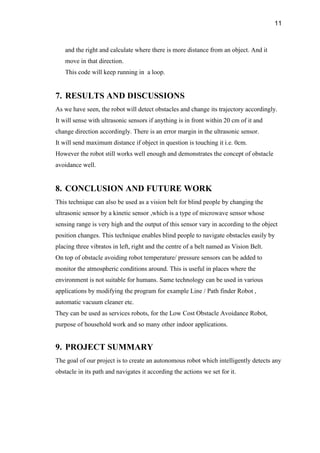
  • 9. 9 Serial.print(cm2); Serial.println(" cm"); } void checkRightDistance() { digitalWrite(trigPin3, LOW); delayMicroseconds(4); digitalWrite(trigPin3, HIGH); delayMicroseconds(10); digitalWrite(trigPin3, LOW); duration3 = pulseIn(echoPin3, HIGH); cm3 = (duration3/2) / 29.1; Serial.print("Right distance: "); Serial.print(cm3); Serial.println(" cm"); } [/code]
  • 10. 10 6.3. Code/Circuit Description The robot is switched on by giving it 9V DC power from an external battery.The motors starts rotating and thus the robot starts moving forward. However we need to know how the ultrasonic sensor work to explain further. The ultrasonic sensor uses sonar to determine the distance to an object. What happens it that:  The ultrasound transmitter (trig pin) emits a high-frequency sound (40 kHz).  The sound travels through the air. If it finds an object, it bounces back to the module.  The ultrasound receiver (echo pin) receives the reflected sound (echo). The time between the transmission and reception of the signal allows us to calculate the distance to an object. This is possible because we know the sound’s velocity in the air. The formula: distance to an object = ((speed of sound in the air)*time)/2 During this time, the center ultrasonic sensor keeps checking to see if anything is in front of it. So we can now explain that the central ulltrasonic sensor keeps checking to see if anything is in front of it within a 20cm distance. If there isnt, it will keep going in a straight line. However, if there is something in front of it, the robot will stop and back up a little, as the sensor senses distance less than 20cm. It will then use the sensors to the left
  • 11. 11 and the right and calculate where there is more distance from an object. And it move in that direction. This code will keep running in a loop. 7. RESULTS AND DISCUSSIONS As we have seen, the robot will detect obstacles and change its trajectory accordingly. It will sense with ultrasonic sensors if anything is in front within 20 cm of it and change direction accordingly. There is an error margin in the ultrasonic sensor. It will send maximum distance if object in question is touching it i.e. 0cm. However the robot still works well enough and demonstrates the concept of obstacle avoidance well. 8. CONCLUSION AND FUTURE WORK This technique can also be used as a vision belt for blind people by changing the ultrasonic sensor by a kinetic sensor ,which is a type of microwave sensor whose sensing range is very high and the output of this sensor vary in according to the object position changes. This technique enables blind people to navigate obstacles easily by placing three vibratos in left, right and the centre of a belt named as Vision Belt. On top of obstacle avoiding robot temperature/ pressure sensors can be added to monitor the atmospheric conditions around. This is useful in places where the environment is not suitable for humans. Same technology can be used in various applications by modifying the program for example Line / Path finder Robot , automatic vacuum cleaner etc. They can be used as services robots, for the Low Cost Obstacle Avoidance Robot, purpose of household work and so many other indoor applications. 9. PROJECT SUMMARY The goal of our project is to create an autonomous robot which intelligently detects any obstacle in its path and navigates it according the actions we set for it.
  • 12. 12 10. PROJECT PICTURES 11. REFERENCES https://www.ncbi.nlm.nih.gov/pmc/articles/PMC8545591/ https://ieeexplore.ieee.org/abstract/document/8570477 https://www.academia.edu/35334413/Obstacle_Avoiding_Smartcar_using_Arduino_an d_Ultrasonic_Sensors_J_Component_Report https://randomnerdtutorials.com/complete-guide-for-ultrasonic-sensor-hc-sr04/ https://forum.arduino.cc/t/digital-pin-0-and-1/475928/7 https://hardwarefun.com/tutorials/controlling-speed-of-dc-motors-using-arduino https://www.researchgate.net/publication/356808148_Ultrasonic_Signal_Implementati on_in_Arduino-Based_Obstacle_Robot_Control_System https://www.slideshare.net/shubhamthakur614/final-report-obstacle-avoiding-roboat https://hardwarefun.com/tutorials/controlling-speed-of-dc-motors-using-arduino https://hardwarefun.com/tutorials/controlling-speed-of-dc-motors-using-arduino