![International Journal of Electrical and Computer Engineering (IJECE)
Vol. 12, No. 5, October 2022, pp. 4722~4733
ISSN: 2088-8708, DOI: 10.11591/ijece.v12i5.pp4722-4733 4722
Journal homepage: http://ijece.iaescore.com
Presentation of a fault tolerance algorithm for design of
quantum-dot cellular automata circuits
Seyed Mehdi Dadgar, Razieh Farazkish, Amir Sahafi
Department of Computer Engineering, South Tehran Branch, Islamic Azad University, Tehran, Iran
Article Info ABSTRACT
Article history:
Received Jun 1, 2020
Revised Jun 18, 2021
Accepted Jun 28, 2022
A novel algorithm for working out the Kink energy of quantum-dot cellular
automata (QCA) circuits and their fault tolerability is introduced. In this
algorithm at first with determining the input values on a specified design, the
calculation between cells makes use of Kink physical relations will be
managed. Therefore, the polarization of any cell and consequently output
cell will be set. Then by determining missed cell(s) on the discussed circuit,
the polarization of output cell will be obtained and by comparing it with safe
state or software simulation, its fault tolerability will be proved. The
proposed algorithm was implemented on a novel and advance fault tolerance
full adder whose performance has been demonstrated. This algorithm could
be implemented on any QCA circuit. Noticeably higher speed of the
algorithm than simulation and traditional manual methods, expandability of
this algorithm for variable circuits, beyond of four-dot square of QCA
circuits, and the investigation of several damaged cells instead just one and
special cell are the advantages of algorithmic action.
Keywords:
Fault tolerance algorithm
Full-adder
Kink energy
Polarization
Quantum-dot cellular automata
This is an open access article under the CC BY-SA license.
Corresponding Author:
Razieh Farazkish
Department of Computer Engineering, South Tehran Branch, Islamic Azad University
Ahang street, Tehran, Iran
Email: r.farazkish@srbiau.ac.ir
1. INTRODUCTION
Nano science and interdepend technology mid biology and genetic molecular sciences and
information technology, are the component of third industrial and scientific evolution in recent years. This
technology is the convergence of different science for further. In this regard, nanoelectronics has many
applications in other sciences [1]. “Very large-scale integration (VLSI)-complementary metal oxide
semiconductor (CMOS)” is a famous and current technology for making electronic circuits. Since it has some
obstacles, in these recent years a lot of studies based on nano electronic technology are down. Quantum-dot
cellular automata (QCA) is a new method in nano scalable for calculations, data transfer and fabrication of
Integrated circuits [2], [3]. Advantages of QCA over todays CMOS VLSI technology are its flexibility in
logical gates design, digital circuits, massive and parallel architectures which is better and more powerful in
some factors like speed, power consumption, and large scale integration capacity [4]. Nevertheless, there are
three drawbacks to QCA technology that have not yet reached the actual construction, which are [5], [6]:
i) normal room temperature causes their efficiency and accuracy to be lost because the QCA circuits work
properly in a certain temperature range, ii) the problem of connecting the output of these nano circuits to
other circuits in the microelectronic world, which has made this technology impractical, and iii) fabrication
defects, which include three models of defects: missing cell, dislocation cell, and misalignment cell. These
three defects were shown in Figures 1(a) misalignment cell, Figure 1(b) missing cell, and Figure 1(c)
dislocation cell [7].](https://image.slidesharecdn.com/20157073080526384em5sep1junn-220909025751-2d816fff/85/Presentation-of-a-fault-tolerance-algorithm-for-design-of-quantum-dot-cellular-automata-circuits-1-320.jpg)
![Int J Elec & Comp Eng ISSN: 2088-8708
Presentation of a fault tolerance algorithm for design of quantum-dot cellular … (Seyed Mehdi Dadgar)
4723
In this research, the main discussion is the third kind or fabrication defects. This faults usually
happen in fabrication and assembling stage. So, fault tolerance circuits design is so essential and necessary.
In recent years many pieces of research and studies were done on QCA fault tolerance circuits design and
many papers in this domain were their results.
In all of these designs, the way of proving fault tolerability is that one key cell in circuit is ignored
and nevertheless, their performance is monitored [8]. Then with gain results, their fault tolerability is proved.
Another important tool for researchers is software simulation for their circuits. In this paper, the main
purpose is to provide an algorithm that performs these calculations. In the other hand target is omitting
simulation and handy calculations and replace them with an optimum, expandable, very high speed and
performance algorithm.
In this regard, we can mention other new technologies that are being studied by scientists. One of
these technologies is vision-based technology [9]. Vision based technology is used as an engineering tool in
digital modules for automatic control of industrial tools [10], [11]. This technology includes the technology
and methods used to automatically extract information from the image, unlike image processing whose
output is another image [12]. The information extracted can be a simple signal, or a more complex set of data
such as the identity, position and orientation of each object in the image. This information can be used for
applications such as automated inspection and process and robot guidance in industry, and security
monitoring and vehicle navigation. This field includes multiple technologies, hardware and software
products, integrated systems, activities, methods, and skills [13]. This technology is practically the only term
used to describe these functions in industrial automation applications; this phrase is less common to describe
the same applications in other environments such as security environments. It seeks to integrate existing
technologies with new methods and use them to solve real-world problems so that the needs of industrial
automation and similar applications are met [14], [15].
In the continuation of this research, we can deal with the idea in the future that the circuit designed
by a designer, considering a series of specific standards is entered into the machine by a camera and after
performing different image processing on it, it is determined which module algorithm is suitable. Then, by
applying the pre-given data in the algorithm, it obtains the necessary output and delivers a graphic file called
the output to the designer.
(a) (b) (c)
Figure 1. Faults on QCA cells: (a) misalignment cell, (b) missing cell, and (c) dislocation cell
2. MATERIALS AND METHOD
2.1. Review of quantum-dot cellular automata
Quantum dot cellular automata is a new architecture in nano-scalable circuit design industrial [16],
[17]. The basic and arithmetic element in QCA design is a quantum cell. Each quantum cell looks like a
square which has four quantum dots in each corner [6]. There are two movable electrons in each cell.
Columbic energy creates two possible states because of their electron locations. These states imply two logic
values. Logical 0 and 1 [18]. These states are shown in Figure 2(a). A binary wire is shown in
Figure 2(b). There are several cells which stand continues and make a binary wire. An inverter could be made
by moving cell like in Figure 2(c) [19]. Majority gate is a useful gate in QCA circuits design. The simplest
majority gate is three-input gate which its output function is ab + ac + bc, where a, b, c are its inputs. A
simple majority gate is shown in Figure 2(d) [20], [21].
These elements are base components for design another gates and circuits in QCA. For example, as
shown in (1), if one input is considered 0 on 3-input majority gate, logical “AND” gate will be found. Or if 1
is considered, logical “OR” will be obtained [22].
(a AND b)=Majority (a, b, 0), (a OR b)=Majority (a, b, 1) (1)
With these methods, other gates or circuits will be designed and implemented. For example, a simple
full-adder is shown in Figure 3 [23].](https://image.slidesharecdn.com/20157073080526384em5sep1junn-220909025751-2d816fff/85/Presentation-of-a-fault-tolerance-algorithm-for-design-of-quantum-dot-cellular-automata-circuits-2-320.jpg)
![ ISSN: 2088-8708
Int J Elec & Comp Eng, Vol. 12, No. 5, October 2022: 4722-4733
4724
(a) (b)
(c) (d)
Figure 2. QCA cells: (a) two available polarizations, (b) binary wire, (c) QCA inverter, and (d) 3-input
majority gate
Figure 3. A simple full adder using three majority gates and two inverters
2.2. QCA implementation
There are four physically models of QCA implementation: metal, molecular, magnetic and
semiconductor QCA [24]. Micro-sized QCA devices have been fabricated with metal. This device is
composed of four aluminum islands (as dots) connected with aluminum oxide tunnel junctions and
capacitors. The area of the tunnel junctions determines the island capacitance (the charging energy of the
dots) and hence, the operating temperature of the device. The device has been fabricated using electron beam
lithography (EBL) and dual shadow evaporation on an oxidized silicon wafer [25]. Semiconductor
implementation of QCA is advantageous due to well understood behavior of existing semiconductors for
which several tools and techniques have been already developed [26]. As an alternative technology,
molecular QCA has several advantages over metal dot QCA. Small cell size (density of up to 1013 devices
per cm2
), a simple manufacturing process, and operation at room temperature are some of the desirable
features of molecular QCA [27], [28]. In magnetic implementation of QCA (MQCA), magneto static
interactions between nanoparticles ensure that the system is bi stable. The moments of the nanoparticles point
either parallel, or anti-parallel with the axis of the chain, Information is propagated via magnetic exchange
interactions as opposed to the electrostatic interactions in metal and molecular implementations [29]. MQCA
provides the advantage of operation at room temperature even with current fabrication techniques. However,
magnetic QCA does not appear to have the switching speed to compete with today’s computers [30].
Majority
Majority
Majoity
a
b
c
a
b
c
Cout
Sum
Majority
Majority
Majority](https://image.slidesharecdn.com/20157073080526384em5sep1junn-220909025751-2d816fff/85/Presentation-of-a-fault-tolerance-algorithm-for-design-of-quantum-dot-cellular-automata-circuits-3-320.jpg)
![Int J Elec & Comp Eng ISSN: 2088-8708
Presentation of a fault tolerance algorithm for design of quantum-dot cellular … (Seyed Mehdi Dadgar)
4725
2.3. Physical relations
More QCA designs are based on square schemes. As shown in Figure 4, all cells are considered as a
square and similar with 18nm side length. All the inter cell spaces are 2 nm. It should be noted that in order
to achieve more stability, electrons of QCA cell are arranged in such a manner that reaches minimum kink
energy (the difference in electrostatic energy between the two polarization states) [30].
Figure 4. Cell distances
In (2), the kink energy between two electrons QCA cells is shown. “U” refers to Kink energy, “k”,
which is called the colonic constant, is a constant coefficient of this ratio whose value is 9×10⁻⁹
, “r” is the
distance between two electrons and “q1”, “q2” refer to electric charges. “k” and “q1”, “q2” are constant values
and “k.q1.q2” is denoted “A” (3). Finally, “Ut” will obtain from all king energy summation at a state. It is
calculated by (4) [2], [4].
𝑈 =
𝑘𝑞1𝑞2
𝑟
(2)
kq1q2=9×10-9
× (1.6)2
×10-38
=23.04×10-29
=A (constant value) (3)
𝑈𝑡 = ∑ 𝑈𝑖
2
𝑖=1 (4)
Finding the output cells polarization is done with computing Kink energy physical relations. With
this method, the QCA circuit designers demonstrate their reliability of their presented designs. For example,
one effective cell which has a direct or significant effect on output cell is ignored and then with using kink
energy relations, the polarization of output cells will be found and fault tolerability of proposed designs will
be proved [2], [30]. In this paper, an algorithm is presented which calculates the kink energy of output cells
in a circuit and then detects its fault tolerability.
3. PROPOSED ALGORITHM
In QCA presented designs, calculating of Kink energy is the basic method to obtain the output
polarization. These actions are done manually in some papers. In other papers, using simulation tools, the
validity of design functions is proved. Now the main target is proposing an algorithm which does these works
as a software. In this way, the method of the proposed algorithm will be described and then it will be
implemented on 3-input majority gate and a full-adder.
3.1. Explain the method
Some functions are considered which can return Kink energy from two neighbor cells, Kink energy
and polarization of 3-input and 5-input majority gate and an inverter separately. These functions are: Kink(I),
3-Maj (a, b, c), 5-Maj (a, b, c, d, e), and INV(I). The base of calculations in all of these is on Kink energy
relations which were shown in (2), (3), and (4). These functions are used to represent an algorithm to obtain
the fault tolerance of existing circuits. In this section we describe King(I) function with details. In this
function, if the input is set on logic 0, there are 0 or 1 possible states for output and if the input is set on logic
1, 0 or 1 output states are feasible. One state of these conditions is presented in Figure 5(a), One possible
state for output with 1 input and Figure 5(b) another possible state for output with 0 input. As noted, the
stable state will be reached based on the lowest kink energy between two logic 0 and 1 for an output.
According to (2)-(4) in section 2.3, 𝑢 =
𝑘𝑞1𝑞2
𝑟
and Kq1q2 as a constant value is 23.04×10⁻²⁹
. So, for
the state (a):
𝑟1𝑥1 = √182 + 22 = 18.11 𝑛𝑚 𝑢 = 1.27 × 10⁻²⁰
𝑟1𝑦1 = 18 + 2 = 20 𝑛𝑚 𝑢 = 1.15 × 10⁻²⁰
18nm
2nm](https://image.slidesharecdn.com/20157073080526384em5sep1junn-220909025751-2d816fff/85/Presentation-of-a-fault-tolerance-algorithm-for-design-of-quantum-dot-cellular-automata-circuits-4-320.jpg)


![Int J Elec & Comp Eng ISSN: 2088-8708
Presentation of a fault tolerance algorithm for design of quantum-dot cellular … (Seyed Mehdi Dadgar)
4729
So far, six functions have been obtained that investigate the states of one and two missing cells.
They are 1Fault-a() for missed cell 5 or 6, 1Fault-b() for missed cell 2 or 4 or 8, 1Fault-c() for missed cell 3
or 9, 2Fault-a() for missed two cells 2, 4 or 2, 8 or 4, 8 or 2, 8 or 3, 5 or 5, 9 or 3, 9, 2fault-b() for missed two
cells 2, 5 or 4, 5 or 5, 8 and finally 2fault-c() for missing two cells 5, 6. Similarly, missing more than two
missed cells could be investigated by proposed algorithm and return the fault tolerability of circuit by it. As
mentioned before, Kink energy and polarization of inverter are calculated by INV(I) function. In this plan,
cells with numbers 1 and 2 are input cells. A fault-tolerance inverter gate with four QCA cells is shown in
Figure 9 [30].
Figure 9. Layout of inverter QCA cell
P3=INV (1), P4=INV (2)
For fault tolerability we have two statuses: i) cell number 1 is missed: In this status, in one state we
will have P3=INV (2) and P4=INV (2); and ii) cell number 2 is missed: In this status, in one state we will
have P3=INV (1) and P4=INV (1). So, if one cell of any seven inverter gates is missed, inverter and total of
the circuit will work correctly.
3.2. Algorithmic implementation of a fault tolerance full adder
A new design of a fault tolerance full adder is shown in Figure 10(a) a new design of a fault tolerant
full-adder and Figure 10(b) QCA layout [18]. Three majority gates with three inputs and two inverters are
used in this plan. The number of used cells in this design is 207 cells with three inputs (a, b, c) and two
outputs (Sum, carry). As shown, there are three blocks with nine cells in the middle of the figure which are
block1, block2, block3. Besides, seven inverter blocks with four cells which mentioned 1, 2, …, 7 could be
seen. Polarization of input cells is constant. In spite, middle cells and outputs are variable. Other cells are
considered as QCA wire. End algorithm on this circuit is summarized in Figure 11 as a flow chart.
(a) (b)
Figure 10. Full-adder (a) a new design of a fault tolerant full-adder and (b) QCA layout
4
3
1
2
Majority
Majority
Majoity
a
b
c
a
b
c
Cout
Sum
Majority
Majority
Majority
Carry
Sum
Maj
Maj
Maj
1
2
3
4
a b c
5
6
7](https://image.slidesharecdn.com/20157073080526384em5sep1junn-220909025751-2d816fff/85/Presentation-of-a-fault-tolerance-algorithm-for-design-of-quantum-dot-cellular-automata-circuits-8-320.jpg)

![ ISSN: 2088-8708
Int J Elec & Comp Eng, Vol. 12, No. 5, October 2022: 4722-4733
4732
5. CONCLUSION
A novel algorithm for validity test of QCA circuits and their fault tolerability is presented. In this
algorithm, input values are entered and with physical Kink energy relations, the polarization of each cell and
finally output cells are returned. Besides, we can ignore one or more cells as missed cells on a QCA circuit
and find its fault tolerability. Outputs of the proposed algorithm were compared with simulation and manual
calculations on a new fault-tolerance full adder and some advantages were found. These advantages are:
much higher speed of proposed algorithm than simulation, expandability of algorithm on any circuit
implementation, this algorithm works in four-dot square state and can generalize for other states like a three-
dot triangle, five-dot pentagon, considering several damaged cells instead of just one and special cell in
traditional ways to prove reliability.
REFERENCES
[1] A. O. Orlov, I. Amlani, G. H. Bernstein, C. S. Lent, and G. L. Snider, “Realization of a functional cell for quantum-dot cellular
automata,” Science, vol. 277, no. 5328, pp. 928–930, Aug. 1997, doi: 10.1126/science.277.5328.928.
[2] S. Mostafa, N. Keivan, and D. Mehdi, “Full adder and full subtractor design in quantum cellular automata,” Majlesi Journal of
Electrical Engineering, vol. 15, no. 1, pp. 33–37, 2021.
[3] X. Yang, L. Cai, H. Huang, and X. Zhao, “A comparative analysis and design of quantum-dot cellular automata memory cell
architecture,” International Journal of Circuit Theory and Applications, vol. 40, no. 1, pp. 93–103, Jan. 2012, doi:
10.1002/cta.710.
[4] R. Farazkish, “Fault-tolerant adder design in quantum-dot cellular automata,” International Journal of Nano Dimension, vol. 8,
no. 1, pp. 40–48, 2017, doi: 10.22034/IJND.2017.24375.
[5] M. Zarei and A. M. Rahmani, “Analysis of vehicular mobility in a dynamic free-flow highway,” Vehicular Communications,
vol. 7, pp. 51–57, Jan. 2017, doi: 10.1016/j.vehcom.2016.12.001.
[6] A. Fijany and B. N. Toomarian, “New design for quantum dots cellular automata to obtain fault-tolerant logic gates,” Journal of
Nanoparticle Research, vol. 3, no. 1, pp. 27–37, 2001, doi: 10.1023/A:1011415529354.
[7] M. Zarei, “Traffic-centric mesoscopic analysis of connectivity in VANETs,” The Computer Journal, vol. 63, no. 2, pp. 203–219,
Feb. 2020, doi: 10.1093/comjnl/bxz094.
[8] R. Farazkish, S. Sayedsalehi, and K. Navi, “Novel design for quantum dots cellular automata to obtain fault-tolerant majority
gate,” Journal of Nanotechnology, vol. 2012, pp. 1–7, 2012, doi: 10.1155/2012/943406.
[9] M. Rungruanganukul and T. Siriborvornratanakul, “Deep learning based gesture classification for hand physical therapy
interactive program,” in Lecture Notes in Computer Science, 2020, pp. 349–358.
[10] C. Kerdvibulvech, “Hand tracking by extending distance transform and hand model in real-time,” Pattern Recognition and Image
Analysis, vol. 25, no. 3, pp. 437–441, Jul. 2015, doi: 10.1134/S1054661815030098.
[11] T. Siriborvornratanakul, “An automatic road distress visual inspection system using an onboard in-car camera,” Advances in
Multimedia, vol. 2018, pp. 1–10, Jun. 2018, doi: 10.1155/2018/2561953.
[12] A. Bandini and J. Zariffa, “Analysis of the hands in egocentric vision: A survey,” arXiv:1912.10867v2, Dec. 2019, doi:
10.1109/TPAMI.2020.2986648.
[13] W. Wang, K. Yu, J. Hugonot, P. Fua, and M. Salzmann, “Recurrent U-net for resource-constrained segmentation,” in 2019
IEEE/CVF International Conference on Computer Vision (ICCV), Oct. 2019, pp. 2142–2151, doi: 10.1109/ICCV.2019.00223.
[14] G. Garcia-Hernando, S. Yuan, S. Baek, and T.-K. Kim, “First-person hand action benchmark with RGB-D videos and 3D hand
pose annotations,” in 2018 IEEE/CVF Conference on Computer Vision and Pattern Recognition, Jun. 2018, pp. 409–419, doi:
10.1109/CVPR.2018.00050.
[15] B. Tekin, F. Bogo, and M. Pollefeys, “H+O: Unified egocentric recognition of 3D hand-object poses and interactions,” in 2019
IEEE/CVF Conference on Computer Vision and Pattern Recognition (CVPR), Jun. 2019, pp. 4506–4515, doi:
10.1109/CVPR.2019.00464.
[16] R. Farazkish, “Robust and reliable design of bio-nanorobotic systems,” Microsystem Technologies, vol. 25, no. 4, pp. 1519–1524,
Apr. 2019, doi: 10.1007/s00542-018-4049-1.
[17] N. Kandasamy, F. Ahmad, D. Ajitha, B. Raj, and N. Telagam, “Quantum dot cellular automata-based scan flip-flop and boundary
scan register,” IETE Journal of Research, pp. 1–14, Oct. 2020, doi: 10.1080/03772063.2020.1831411.
[18] H. Alamdar, G. Ardeshir, and M. Gholami, “Novel quantum‐dot cellular automata implementation of flip‐flop and phase‐
frequency detector based on nand‐nor‐inverter gates,” International Journal of Circuit Theory and Applications, vol. 49, no. 1,
pp. 196–212, Jan. 2021, doi: 10.1002/cta.2825.
[19] M. Zahmatkesh, S. Tabrizchi, S. Mohammadyan, K. Navi, and N. Bagherzadeh, “Robust coplanar full adder based on novel
inverter in quantum cellular automata,” International Journal of Theoretical Physics, vol. 58, no. 2, pp. 639–655, Feb. 2019, doi:
10.1007/s10773-018-3961-6.
[20] Z. Amirzadeh and M. Gholami, “Counters designs with minimum number of cells and area in the quantum-dot cellular automata
technology,” International Journal of Theoretical Physics, vol. 58, no. 6, pp. 1758–1775, Jun. 2019, doi: 10.1007/s10773-019-
04070-2.
[21] R. Farazkish, “A new quantum-dot cellular automata fault-tolerant full-adder,” Journal of Computational Electronics, vol. 14,
no. 2, pp. 506–514, Jun. 2015, doi: 10.1007/s10825-015-0668-2.
[22] S. Zoka and M. Gholami, “A novel rising Edge triggered resettable D flip-flop using five input majority gate,” Microprocessors
and Microsystems, vol. 61, pp. 327–335, Sep. 2018, doi: 10.1016/j.micpro.2018.06.006.
[23] R. Farazkish, “A new quantum-dot cellular automata fault-tolerant five-input majority gate,” Journal of Nanoparticle Research,
vol. 16, no. 2, Feb. 2014, doi: 10.1007/s11051-014-2259-8.
[24] R. Binaei and M. Gholami, “Design of multiplexer-based D flip-flop with set and reset ability in quantum dot cellular automata
nanotechnology,” International Journal of Theoretical Physics, vol. 58, no. 3, pp. 687–699, Mar. 2019, doi: 10.1007/s10773-018-
3967-0.
[25] R. Farazkish and F. Khodaparast, “Design and characterization of a new fault-tolerant full-adder for quantum-dot cellular
automata,” Microprocessors and Microsystems, vol. 39, no. 6, pp. 426–433, Aug. 2015, doi: 10.1016/j.micpro.2015.04.004.](https://image.slidesharecdn.com/20157073080526384em5sep1junn-220909025751-2d816fff/85/Presentation-of-a-fault-tolerance-algorithm-for-design-of-quantum-dot-cellular-automata-circuits-11-320.jpg)
![Int J Elec & Comp Eng ISSN: 2088-8708
Presentation of a fault tolerance algorithm for design of quantum-dot cellular … (Seyed Mehdi Dadgar)
4733
[26] T. N. Sasamal, A. K. Singh, and U. Ghanekar, “Design of QCA-based D flip flop and memory cell using rotated majority gate,” in
Smart Innova-tions in Communication and Computational Sciences, 2019, pp. 233–247.
[27] M. Gholami and S. Zoka, “Two novel D-Flip flops with level triggered reset in quantum dot cellular automata technology,”
International Journal of Engineering, vol. 31, no. 3, pp. 415–421, 2018.
[28] N. Moosavi, K. Navi, and V. Aghazarian, “Ultra-low-cost full adder cell using the nonlinear effect in four-input quantum dot
cellular automata majority gate,” International Journal of Nonlinear Analysis and Applications, vol. 11, no. 2, pp. 1–16, 2020,
doi: 10.22075/ijnaa.2020.19577.2088.
[29] S. Ahmed, S. F. Naz, and S. M. Bhat, “Design of quantum-dot cellular automata technology based cost-efficient polar encoder for
nanocommunication systems,” Suhaib Ahmed Syed Farah Naz Soha Maqbool Bhat, vol. 33, no. 18, 2020, doi: 10.1002/dac.4630.
[30] V. K. Sharma, “Optimal design for digital comparator using QCA nanotechnology with energy estimation,” International Journal
of Numerical Modelling: Electronic Networks, Devices and Fields, vol. 34, no. 2, Mar. 2021, doi: 10.1002/jnm.2822.
BIOGRAPHIES OF AUTHORS
Mehdi Dadgar received the B.Sc. degree from Islamic Azad University of South
Tehran, Iran in 2001, M.Sc. degree from Science and Research Branch of Islamic Azad
University, Tehran, Iran, in 2006, and now he is a Ph.D. candidate in Islamic Azad University
of South Tehran. All in computer engineering. He is a faculty member in Department of
Computer Engineering, Roudehen Branch, Islamic Azad University, Tehran, Iran. His current
research interest is circuits design with nano electronic technology. He can be contacted at
email: mdadgar@riau.ac.ir.
Razieh Farazkish received the B.S. degree in computer engineering from the
IAU, Central Tehran Branch (2007) and the M.S. (2009) and Ph.D. (2012) degrees in computer
engineering from the IAU, Science and Research Branch. In 2012, she joined the Department
of Computer Engineering, IAU, South Tehran Branch, as a professor. Her current research
interests include quantum-dot cellular automata, fault tolerance, Nano electronic circuits,
nano computing, testing and design of digital systems. She can be contacted at email:
r.farazkish@srbiau.ac.ir.
Amir Sahafi received the B.Sc. degree from Shahed University of Tehran, Iran in
2005, M.Sc. and Ph.D. degrees both from Science and Research Branch of Islamic Azad
University, Tehran, Iran, in 2007 and 2012, all in computer engineering. He is an Assistant
Professor in Department of Computer Engineering, South Tehran Branch, Islamic Azad
University, Tehran, Iran. His current research interests are Nono electronics, Distributed and
Cloud computing. He can be contacted at email: a.sahafi@srbiau.ac.ir.](https://image.slidesharecdn.com/20157073080526384em5sep1junn-220909025751-2d816fff/85/Presentation-of-a-fault-tolerance-algorithm-for-design-of-quantum-dot-cellular-automata-circuits-12-320.jpg)
Presentation of a fault tolerance algorithm for design of quantum-dot cellular automata circuits
- 1. International Journal of Electrical and Computer Engineering (IJECE) Vol. 12, No. 5, October 2022, pp. 4722~4733 ISSN: 2088-8708, DOI: 10.11591/ijece.v12i5.pp4722-4733 4722 Journal homepage: http://ijece.iaescore.com Presentation of a fault tolerance algorithm for design of quantum-dot cellular automata circuits Seyed Mehdi Dadgar, Razieh Farazkish, Amir Sahafi Department of Computer Engineering, South Tehran Branch, Islamic Azad University, Tehran, Iran Article Info ABSTRACT Article history: Received Jun 1, 2020 Revised Jun 18, 2021 Accepted Jun 28, 2022 A novel algorithm for working out the Kink energy of quantum-dot cellular automata (QCA) circuits and their fault tolerability is introduced. In this algorithm at first with determining the input values on a specified design, the calculation between cells makes use of Kink physical relations will be managed. Therefore, the polarization of any cell and consequently output cell will be set. Then by determining missed cell(s) on the discussed circuit, the polarization of output cell will be obtained and by comparing it with safe state or software simulation, its fault tolerability will be proved. The proposed algorithm was implemented on a novel and advance fault tolerance full adder whose performance has been demonstrated. This algorithm could be implemented on any QCA circuit. Noticeably higher speed of the algorithm than simulation and traditional manual methods, expandability of this algorithm for variable circuits, beyond of four-dot square of QCA circuits, and the investigation of several damaged cells instead just one and special cell are the advantages of algorithmic action. Keywords: Fault tolerance algorithm Full-adder Kink energy Polarization Quantum-dot cellular automata This is an open access article under the CC BY-SA license. Corresponding Author: Razieh Farazkish Department of Computer Engineering, South Tehran Branch, Islamic Azad University Ahang street, Tehran, Iran Email: [email protected] 1. INTRODUCTION Nano science and interdepend technology mid biology and genetic molecular sciences and information technology, are the component of third industrial and scientific evolution in recent years. This technology is the convergence of different science for further. In this regard, nanoelectronics has many applications in other sciences [1]. “Very large-scale integration (VLSI)-complementary metal oxide semiconductor (CMOS)” is a famous and current technology for making electronic circuits. Since it has some obstacles, in these recent years a lot of studies based on nano electronic technology are down. Quantum-dot cellular automata (QCA) is a new method in nano scalable for calculations, data transfer and fabrication of Integrated circuits [2], [3]. Advantages of QCA over todays CMOS VLSI technology are its flexibility in logical gates design, digital circuits, massive and parallel architectures which is better and more powerful in some factors like speed, power consumption, and large scale integration capacity [4]. Nevertheless, there are three drawbacks to QCA technology that have not yet reached the actual construction, which are [5], [6]: i) normal room temperature causes their efficiency and accuracy to be lost because the QCA circuits work properly in a certain temperature range, ii) the problem of connecting the output of these nano circuits to other circuits in the microelectronic world, which has made this technology impractical, and iii) fabrication defects, which include three models of defects: missing cell, dislocation cell, and misalignment cell. These three defects were shown in Figures 1(a) misalignment cell, Figure 1(b) missing cell, and Figure 1(c) dislocation cell [7].
- 2. Int J Elec & Comp Eng ISSN: 2088-8708 Presentation of a fault tolerance algorithm for design of quantum-dot cellular … (Seyed Mehdi Dadgar) 4723 In this research, the main discussion is the third kind or fabrication defects. This faults usually happen in fabrication and assembling stage. So, fault tolerance circuits design is so essential and necessary. In recent years many pieces of research and studies were done on QCA fault tolerance circuits design and many papers in this domain were their results. In all of these designs, the way of proving fault tolerability is that one key cell in circuit is ignored and nevertheless, their performance is monitored [8]. Then with gain results, their fault tolerability is proved. Another important tool for researchers is software simulation for their circuits. In this paper, the main purpose is to provide an algorithm that performs these calculations. In the other hand target is omitting simulation and handy calculations and replace them with an optimum, expandable, very high speed and performance algorithm. In this regard, we can mention other new technologies that are being studied by scientists. One of these technologies is vision-based technology [9]. Vision based technology is used as an engineering tool in digital modules for automatic control of industrial tools [10], [11]. This technology includes the technology and methods used to automatically extract information from the image, unlike image processing whose output is another image [12]. The information extracted can be a simple signal, or a more complex set of data such as the identity, position and orientation of each object in the image. This information can be used for applications such as automated inspection and process and robot guidance in industry, and security monitoring and vehicle navigation. This field includes multiple technologies, hardware and software products, integrated systems, activities, methods, and skills [13]. This technology is practically the only term used to describe these functions in industrial automation applications; this phrase is less common to describe the same applications in other environments such as security environments. It seeks to integrate existing technologies with new methods and use them to solve real-world problems so that the needs of industrial automation and similar applications are met [14], [15]. In the continuation of this research, we can deal with the idea in the future that the circuit designed by a designer, considering a series of specific standards is entered into the machine by a camera and after performing different image processing on it, it is determined which module algorithm is suitable. Then, by applying the pre-given data in the algorithm, it obtains the necessary output and delivers a graphic file called the output to the designer. (a) (b) (c) Figure 1. Faults on QCA cells: (a) misalignment cell, (b) missing cell, and (c) dislocation cell 2. MATERIALS AND METHOD 2.1. Review of quantum-dot cellular automata Quantum dot cellular automata is a new architecture in nano-scalable circuit design industrial [16], [17]. The basic and arithmetic element in QCA design is a quantum cell. Each quantum cell looks like a square which has four quantum dots in each corner [6]. There are two movable electrons in each cell. Columbic energy creates two possible states because of their electron locations. These states imply two logic values. Logical 0 and 1 [18]. These states are shown in Figure 2(a). A binary wire is shown in Figure 2(b). There are several cells which stand continues and make a binary wire. An inverter could be made by moving cell like in Figure 2(c) [19]. Majority gate is a useful gate in QCA circuits design. The simplest majority gate is three-input gate which its output function is ab + ac + bc, where a, b, c are its inputs. A simple majority gate is shown in Figure 2(d) [20], [21]. These elements are base components for design another gates and circuits in QCA. For example, as shown in (1), if one input is considered 0 on 3-input majority gate, logical “AND” gate will be found. Or if 1 is considered, logical “OR” will be obtained [22]. (a AND b)=Majority (a, b, 0), (a OR b)=Majority (a, b, 1) (1) With these methods, other gates or circuits will be designed and implemented. For example, a simple full-adder is shown in Figure 3 [23].
- 3. ISSN: 2088-8708 Int J Elec & Comp Eng, Vol. 12, No. 5, October 2022: 4722-4733 4724 (a) (b) (c) (d) Figure 2. QCA cells: (a) two available polarizations, (b) binary wire, (c) QCA inverter, and (d) 3-input majority gate Figure 3. A simple full adder using three majority gates and two inverters 2.2. QCA implementation There are four physically models of QCA implementation: metal, molecular, magnetic and semiconductor QCA [24]. Micro-sized QCA devices have been fabricated with metal. This device is composed of four aluminum islands (as dots) connected with aluminum oxide tunnel junctions and capacitors. The area of the tunnel junctions determines the island capacitance (the charging energy of the dots) and hence, the operating temperature of the device. The device has been fabricated using electron beam lithography (EBL) and dual shadow evaporation on an oxidized silicon wafer [25]. Semiconductor implementation of QCA is advantageous due to well understood behavior of existing semiconductors for which several tools and techniques have been already developed [26]. As an alternative technology, molecular QCA has several advantages over metal dot QCA. Small cell size (density of up to 1013 devices per cm2 ), a simple manufacturing process, and operation at room temperature are some of the desirable features of molecular QCA [27], [28]. In magnetic implementation of QCA (MQCA), magneto static interactions between nanoparticles ensure that the system is bi stable. The moments of the nanoparticles point either parallel, or anti-parallel with the axis of the chain, Information is propagated via magnetic exchange interactions as opposed to the electrostatic interactions in metal and molecular implementations [29]. MQCA provides the advantage of operation at room temperature even with current fabrication techniques. However, magnetic QCA does not appear to have the switching speed to compete with today’s computers [30]. Majority Majority Majoity a b c a b c Cout Sum Majority Majority Majority
- 4. Int J Elec & Comp Eng ISSN: 2088-8708 Presentation of a fault tolerance algorithm for design of quantum-dot cellular … (Seyed Mehdi Dadgar) 4725 2.3. Physical relations More QCA designs are based on square schemes. As shown in Figure 4, all cells are considered as a square and similar with 18nm side length. All the inter cell spaces are 2 nm. It should be noted that in order to achieve more stability, electrons of QCA cell are arranged in such a manner that reaches minimum kink energy (the difference in electrostatic energy between the two polarization states) [30]. Figure 4. Cell distances In (2), the kink energy between two electrons QCA cells is shown. “U” refers to Kink energy, “k”, which is called the colonic constant, is a constant coefficient of this ratio whose value is 9×10⁻⁹ , “r” is the distance between two electrons and “q1”, “q2” refer to electric charges. “k” and “q1”, “q2” are constant values and “k.q1.q2” is denoted “A” (3). Finally, “Ut” will obtain from all king energy summation at a state. It is calculated by (4) [2], [4]. 𝑈 = 𝑘𝑞1𝑞2 𝑟 (2) kq1q2=9×10-9 × (1.6)2 ×10-38 =23.04×10-29 =A (constant value) (3) 𝑈𝑡 = ∑ 𝑈𝑖 2 𝑖=1 (4) Finding the output cells polarization is done with computing Kink energy physical relations. With this method, the QCA circuit designers demonstrate their reliability of their presented designs. For example, one effective cell which has a direct or significant effect on output cell is ignored and then with using kink energy relations, the polarization of output cells will be found and fault tolerability of proposed designs will be proved [2], [30]. In this paper, an algorithm is presented which calculates the kink energy of output cells in a circuit and then detects its fault tolerability. 3. PROPOSED ALGORITHM In QCA presented designs, calculating of Kink energy is the basic method to obtain the output polarization. These actions are done manually in some papers. In other papers, using simulation tools, the validity of design functions is proved. Now the main target is proposing an algorithm which does these works as a software. In this way, the method of the proposed algorithm will be described and then it will be implemented on 3-input majority gate and a full-adder. 3.1. Explain the method Some functions are considered which can return Kink energy from two neighbor cells, Kink energy and polarization of 3-input and 5-input majority gate and an inverter separately. These functions are: Kink(I), 3-Maj (a, b, c), 5-Maj (a, b, c, d, e), and INV(I). The base of calculations in all of these is on Kink energy relations which were shown in (2), (3), and (4). These functions are used to represent an algorithm to obtain the fault tolerance of existing circuits. In this section we describe King(I) function with details. In this function, if the input is set on logic 0, there are 0 or 1 possible states for output and if the input is set on logic 1, 0 or 1 output states are feasible. One state of these conditions is presented in Figure 5(a), One possible state for output with 1 input and Figure 5(b) another possible state for output with 0 input. As noted, the stable state will be reached based on the lowest kink energy between two logic 0 and 1 for an output. According to (2)-(4) in section 2.3, 𝑢 = 𝑘𝑞1𝑞2 𝑟 and Kq1q2 as a constant value is 23.04×10⁻²⁹ . So, for the state (a): 𝑟1𝑥1 = √182 + 22 = 18.11 𝑛𝑚 𝑢 = 1.27 × 10⁻²⁰ 𝑟1𝑦1 = 18 + 2 = 20 𝑛𝑚 𝑢 = 1.15 × 10⁻²⁰ 18nm 2nm
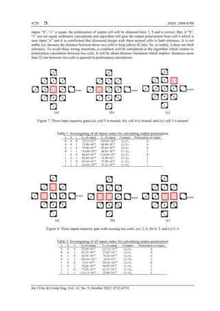
- 5. ISSN: 2088-8708 Int J Elec & Comp Eng, Vol. 12, No. 5, October 2022: 4722-4733 4726 𝑟2𝑥1 = 18 + 2 = 20 𝑛𝑚 𝑢 = 1.15 × 10⁻²⁰ 𝑟2𝑦1 = √382 + 182 = 42.5 𝑛𝑚 𝑢 = 1.27 × 10⁻²⁰ 𝑈11 = (1.27 + 1.15 + 1.15 + 1.27) × 10−20 = 4.84 × 10⁻²⁰ For the state (b) we will have: 𝑟1𝑥0 = √182 + 202 = 26.9 𝑛𝑚 𝑢 = 0.86 × 10⁻²⁰ 𝑟1𝑦0 = 2 𝑛𝑚 𝑢 = 11.52 × 10⁻²⁰ 𝑟2𝑥0 = 18 + 18 + 2 = 38 𝑛𝑚 𝑢 = 0.61 × 10⁻²⁰ 𝑟2𝑦0 = √182 + 202 = 26.9 𝑛𝑚 𝑢 = 0.86 × 10⁻²⁰ 𝑈00 = (0.86 + 11.52 + 0.61 + 0.86) × 10−20 = 13.84 × 10⁻²⁰ Based on the calculations performed above, U11 is lower than U00, so the state (a) or logic ”1” is more stable. As you can see, doing the above calculations manually is very time consuming and significantly reduces the speed. Since the speed issue in new technologies, such as nanoelectronics and nanorobotics, is very important, it would be difficult to perform manual calculations in the case of complex circuits. Thus, there is a demand for an algorithm to perform these computations. In the proposed algorithm, there is a Kink(I) function which calculates these computations by its input parameter. This parameter is the logical value of the input cell. The polarization of output cell will be returned by Kink(I) function. The details of the King(I) function are shown in function 1. King(I) { Input (I); a=23.04; if (I=1) { // we have two condition for “I” input: 0 or 1 r1.x0=a/2; r1. y0=a/26.9; r2.x0=a/26.9; r2. y0=a/38; // Figure 5(b) r1.x1=a/18.11; r1. y1=a/20; r2.x1=a/20; r2. y1=a/42.5; // Figure 5(a) Ux0=r1x0+r2x0; Uy0=r1y0+r2y0; U00=Ux0+Uy0; // “r” is distance between 2 electrons. Ux1=r1x1+r2x1; Uy1=r1y1+r2y1; U11=Ux1+Uy1; If U00>U11 then (output is “1” and king energy=U11) else (output is “0” and king energy =U00) }} // this calculation is down for input with 1 value. We have like these for input 0 Function 1. King(I) A new design of a fault tolerance 3-input majority is shown in Figure 6. The number of used cells in this design is thirteen cells with three inputs (a, b, c) and one output. Its fault tolerability is demonstrated before. (a) (b) Figure 5. Two possible states for cells: (a) one possible state for output with 1 input and (b) another possible state for output with 0 input Polarization of output cell will be gained from 3-Maj (a, b, c) and Kink(I) functions in three stages: polarization of cells 2, 4, 8 will be obtained by calling Kink(a), Kink(b), and Kink(c) functions in the first stage. P4=Kink(a); P2=Kink(b); P8=Kink(c). Then in the second stage, considering the obtained values from the last stage, cells with numbers 5 by calling 3-Maj (P2, P4, P8) function, 3 by calling Kink(P2) and 9 by calling Kink(P8) will get their polarizations too. Finally, number 6 cell which is connected to output cell, will get its polarization from 3, 5 and 9 by calling 3-Maj (P3, P5, P9) function. Now its reliability could be investigated. There are some states for testing the fault tolerability. They could be one and two missed cells. At first, it is considered that the main cell of three input majority (device cell) is missed as shown in Figure 7(a), cell number 5.
- 6. Int J Elec & Comp Eng ISSN: 2088-8708 Presentation of a fault tolerance algorithm for design of quantum-dot cellular … (Seyed Mehdi Dadgar) 4727 Figure 6. Fault tolerance 3-input majority gate In this state algorithm will execute as follow: First stage: P4=Kink(a), P2=Kink(b), P8=Kink(c). These mean that the polarization of cells 2, 4, 8 will be obtained. So, these cells will simply get their polarization from inputs. In the second state, P3=Kink (2), P9=Kink (8). Finally, in the third state: cell 4 has a half effect than other cells (3 and 9). So, cell 6 will get its polarization: P6=5-Maj (P3, P3, P9, P9, P4). Because of the distance ratio, cell 3 and cell 9 have double effect on cell 6 polarization than cell 4. So, we can consider that the polarization of cell 6 will be calculated by a five-input majority gate. Investigating an example: If we consider a= 1, b= 0, c= 1, the result must be 1: - In the first stage: After calling Kink(I) function for cell 4, its kink energy will obtain 4.12×10⁻²⁰ and its polarization will be 1. In this way, the polarization of cell 2 and 8 will obtain 0, 1. - In the second stage: The polarization of 3 will be 0 and 9 will equal 1. - In third stage: P6= 5-Maj (P3, P3, P9, P9, P4) = 5-Maj (0, 0, 1, 1, 1) = 1. So, output logic will be 1. After investigating all states of inputs, outputs were obtained in the Table 1. This table demonstrates that if the cell 5 is missed, this circuit will work correctly. Because the results obtained in Table 1 are the same as the expected results from the output of this majority gate with the given inputs. For cell 6, we have similar conditions as cell 5. For other cells, this way is similar to a little change. Missing cells, which are connected to inputs directly as shown in Figure 7(b), are 2, 4, 8 which have the same way. Cells 3 and 9 have the same state to prove fault tolerability, if they are missed as shown in Figure 7(c). As a result, this algorithm says that if one cell of any one of three majority gates is missed, majority gates and a total of this circuit will work correctly. If one of the states does not have the correct answer, the algorithm declares that the circuit is not fault tolerant. So, there are three similar functions for any state above as missing cell for fault tolerability investigation. In the second state as shown in Figure 8, two missed cells are considered. For example, missing cells number 2 and 4 are considered as shown in Figure 8(a). The state with missing cells number 4, 8 and missing cells number 2, 4 have a similar position. This means that if cells 4 and 8 are lost instead of cells 2 and 4, the same output polarization procedure is obtained due to the similar position of cell 8 to cell 2. For this case the algorithm will calculate the output polarization in three stages: First stage cells 1, 7, 8 get their polarization: P1=5-Maj (a, a, b, b, c), P7=5-Maj (a, a, c, c, b), P8=Kink(c). In the first stage of polarization, cells 1, 7 and 8 are calculated because they are the closest cells affected by the inputs and affect the rest of the cells. 5-Maj (a, a, b, b, c) means that if a and b have equal polarization, cell 1 has their polarizations and if they do not be equal, input c is determiner. In second stage: P5=3-Maj (8, 7, 1), P9=Kink (8), P3=Kink(b) and finally in third stage P6=3-Maj (3,5,9). Investigating an example on inputs: (a=1, b=0, c=1): Stage 1: P1=5-Maj (1, 1, 0, 0, 1) =1, P7=5Maj (1, 1, 1, 1, 0)=1. Stage 2: P5=3-Maj (8, 7, 1) =3Maj (1 ,1 ,1) =1, P9=Kink (8)=1, P3=Kink(b)=0. Stage 3: P6=3-Maj (3, 5, 9) = (0, 1, 1)=1. The output of three inputs majority gate with a=1, b=0, c=1 notwithstanding two cells is missed gains 1 and it is correct. If we investigate the second state which is shown in Figure 8(b), the algorithm will say that it is fault tolerance. It results that this design with two missed cells with discussed locations is fault tolerance as shown in Table 2. In missed cells 3,9 or 3,5 or 5,9 the algorithm is the same. In Figure 8(b), another state of missing two cells is shown. After investigating this state in the algorithm, the gained result showed that it works correctly and fault tolerance. Missing two cells with numbers: 2, 5 and 5, 8 are similar. In Figure 8(c), two cells with numbers 5, 6 are missing. In this state, if b 1 2 3 4 6 7 a 9 8 c output 5
- 7. ISSN: 2088-8708 Int J Elec & Comp Eng, Vol. 12, No. 5, October 2022: 4722-4733 4728 inputs “b”, “c” is equal, the polarization of output cell will be obtained from 3, 9 and is correct. But, if “b”, “c” are not equal, arithmetic calculations and algorithm will gain the output polarization from cell 4 which is near input “a” and it is certificated that discussed design with these missed cells is fault tolerance. It is not stable yet, because the distance between these two cells is long (about 42 nm). So, in reality, it does not fault tolerance. To avoid these wrong situations, a condition will be considered in the algorithm which returns to polarization calculation between two cells. It will be about distance limitation which implies: distances more than 22 nm between two cells is ignored in polarization calculations. (a) (b) (c) Figure 7. Three input majority gates (a): cell 5 is missed, (b): cell 4 is missed, and (c): cell 3 is missed Table 1. Investigating of all inputs states for calculating output polarization a b c U0 of output U1 of output Compare Polarization of output 0 0 0 37.12×10⁻²⁰ 124.55×10⁻²⁰ U0<U1 0 0 0 1 75.98×10⁻²⁰ 85.69×10⁻²⁰ U0<U1 0 0 1 0 75.98×10⁻²⁰ 85.69×10⁻²⁰ U0<U1 0 0 1 1 114.84×10⁻²⁰ 46.83×10⁻²⁰ U1<U0 1 1 0 0 46.83×10⁻²⁰ 114.84×10⁻²⁰ U0<U1 0 1 0 1 85.69×10⁻²⁰ 75.98×10⁻²⁰ U1<U0 1 1 1 0 85.69×10⁻²⁰ 75.98×10⁻²⁰ U1<U0 1 1 1 1 124.55×10⁻²⁰ 37.12×10⁻²⁰ U1<U0 1 (a) (b) (c) Figure 8. Three inputs majority gate with missing two cells: (a): 2, 4, (b) 4, 5, and (c) 5, 6 Table 2. Investigating of all inputs states for calculating output polarization a b c U0 of output U1 of output Compare Polarization of output 0 0 0 25.69×10⁻²⁰ 113.12×10⁻²⁰ U0<U1 0 0 0 1 67.31×10⁻²⁰ 77.02×10⁻²⁰ U0<U1 0 0 1 0 64.55×10⁻²⁰ 74.26×10⁻²⁰ U0<U1 0 0 1 1 103.41×10⁻²⁰ 35.4×10⁻²⁰ U1<U0 1 1 0 0 35.4×10⁻²⁰ 103.41×10⁻²⁰ U0<U1 0 1 0 1 74.26×10⁻²⁰ 64.55×10⁻²⁰ U1<U0 1 1 1 0 77.02×10⁻²⁰ 67.31×10⁻²⁰ U1<U0 1 1 1 1 113.12×10⁻²⁰ 25.69×10⁻²⁰ U1<U0 1
- 8. Int J Elec & Comp Eng ISSN: 2088-8708 Presentation of a fault tolerance algorithm for design of quantum-dot cellular … (Seyed Mehdi Dadgar) 4729 So far, six functions have been obtained that investigate the states of one and two missing cells. They are 1Fault-a() for missed cell 5 or 6, 1Fault-b() for missed cell 2 or 4 or 8, 1Fault-c() for missed cell 3 or 9, 2Fault-a() for missed two cells 2, 4 or 2, 8 or 4, 8 or 2, 8 or 3, 5 or 5, 9 or 3, 9, 2fault-b() for missed two cells 2, 5 or 4, 5 or 5, 8 and finally 2fault-c() for missing two cells 5, 6. Similarly, missing more than two missed cells could be investigated by proposed algorithm and return the fault tolerability of circuit by it. As mentioned before, Kink energy and polarization of inverter are calculated by INV(I) function. In this plan, cells with numbers 1 and 2 are input cells. A fault-tolerance inverter gate with four QCA cells is shown in Figure 9 [30]. Figure 9. Layout of inverter QCA cell P3=INV (1), P4=INV (2) For fault tolerability we have two statuses: i) cell number 1 is missed: In this status, in one state we will have P3=INV (2) and P4=INV (2); and ii) cell number 2 is missed: In this status, in one state we will have P3=INV (1) and P4=INV (1). So, if one cell of any seven inverter gates is missed, inverter and total of the circuit will work correctly. 3.2. Algorithmic implementation of a fault tolerance full adder A new design of a fault tolerance full adder is shown in Figure 10(a) a new design of a fault tolerant full-adder and Figure 10(b) QCA layout [18]. Three majority gates with three inputs and two inverters are used in this plan. The number of used cells in this design is 207 cells with three inputs (a, b, c) and two outputs (Sum, carry). As shown, there are three blocks with nine cells in the middle of the figure which are block1, block2, block3. Besides, seven inverter blocks with four cells which mentioned 1, 2, …, 7 could be seen. Polarization of input cells is constant. In spite, middle cells and outputs are variable. Other cells are considered as QCA wire. End algorithm on this circuit is summarized in Figure 11 as a flow chart. (a) (b) Figure 10. Full-adder (a) a new design of a fault tolerant full-adder and (b) QCA layout 4 3 1 2 Majority Majority Majoity a b c a b c Cout Sum Majority Majority Majority Carry Sum Maj Maj Maj 1 2 3 4 a b c 5 6 7
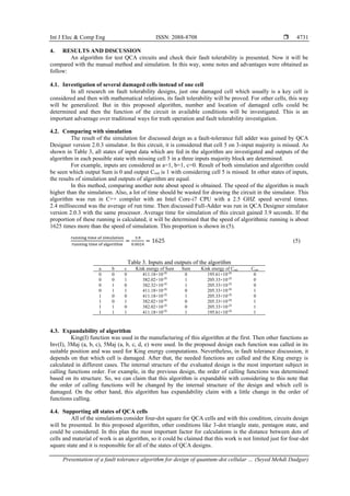
- 9. ISSN: 2088-8708 Int J Elec & Comp Eng, Vol. 12, No. 5, October 2022: 4722-4733 4730 As shown in Figure 11, Kink energy of output cell and its polarization could be obtained in safe mode at the first. Next, the algorithm can prove the fault tolerability of design. It will start by determining the number of missed cells. Kink energy of output cells will be gained by calling related functions which were discussed in these conditions. Fault tolerability of the QCA design will be gained by comparing output polarization in these conditions with a safe state. Figure 11. Flow chart of the proposed algorithm Input a,b,c values start Calculating kink energy of out puts Out put the polarization of outputs NO Yes Which cell is missed? Is it in Majority blocks? Calling one of three functions for kink energy depending on missed cell location Enter number of missed cells Is it one cell? Yes Compare the outputs with safe state Safe state Are Out puts correct? This circuits is fault tolerance with above missed cell(s) Yes This circuits is not fault tolerance with above missed cell(s) NO NO Is it in inverter blocks? Calling inverter function for kink energy Yes Which paired cells are missed? Calling one of three functions for kink energy depending on paired missed cells location Are they 2 or 3? 2 cells 3 cells Which three cells are missed? Calling one of functions for kink energy depending on three missed cells location END
- 10. Int J Elec & Comp Eng ISSN: 2088-8708 Presentation of a fault tolerance algorithm for design of quantum-dot cellular … (Seyed Mehdi Dadgar) 4731 4. RESULTS AND DISCUSSION An algorithm for test QCA circuits and check their fault tolerability is presented. Now it will be compared with the manual method and simulation. In this way, some notes and advantages were obtained as follow: 4.1. Investigation of several damaged cells instead of one cell In all research on fault tolerability designs, just one damaged cell which usually is a key cell is considered and then with mathematical relations, its fault tolerability will be proved. For other cells, this way will be generalized. But in this proposed algorithm, number and location of damaged cells could be determined and then the function of the circuit in available conditions will be investigated. This is an important advantage over traditional ways for truth operation and fault tolerability investigation. 4.2. Comparing with simulation The result of the simulation for discussed deign as a fault-tolerance full adder was gained by QCA Designer version 2.0.3 simulator. In this circuit, it is considered that cell 5 on 3-input majority is missed. As shown in Table 3, all states of input data which are fed in the algorithm are investigated and outputs of the algorithm in each possible state with missing cell 5 in a three inputs majority block are determined. For example, inputs are considered as a=1, b=1, c=0. Result of both simulation and algorithm could be seen which output Sum is 0 and output Cout is 1 with considering cell 5 is missed. In other states of inputs, the results of simulation and outputs of algorithm are equal. In this method, comparing another note about speed is obtained. The speed of the algorithm is much higher than the simulation. Also, a lot of time should be wasted for drawing the circuit in the simulator. This algorithm was run in C++ compiler with an Intel Core-i7 CPU with a 2.5 GHZ speed several times. 2.4 millisecond was the average of run time. Then discussed Full-Adder was run in QCA Designer simulator version 2.0.3 with the same processor. Average time for simulation of this circuit gained 3.9 seconds. If the proportion of these running is calculated, it will be determined that the speed of algorithmic running is about 1625 times more than the speed of simulation. This proportion is shown in (5). running time of simulation running time of algorithm = 3.9 0.0024 = 1625 (5) Table 3. Inputs and outputs of the algorithm a b c Kink energy of Sum Sum Kink energy of Cout Cout 0 0 0 411.18×10⁻²⁰ 0 195.61×10⁻²⁰ 0 0 0 1 382.02×10⁻²⁰ 1 205.33×10⁻²⁰ 0 0 1 0 382.32×10⁻²⁰ 1 205.33×10⁻²⁰ 0 0 1 1 411.18×10⁻²⁰ 0 205.33×10⁻²⁰ 1 1 0 0 411.18×10⁻²⁰ 1 205.33×10⁻²⁰ 0 1 0 1 382.02×10⁻²⁰ 0 205.33×10⁻²⁰ 1 1 1 0 382.02×10⁻²⁰ 0 205.33×10⁻²⁰ 1 1 1 1 411.18×10⁻²⁰ 1 195.61×10⁻²⁰ 1 4.3. Expandability of algorithm King(I) function was used in the manufacturing of this algorithm at the first. Then other functions as Inv(I), 3Maj (a, b, c), 5Maj (a, b, c, d, e) were used. In the proposed design each function was called in its suitable position and was used for King energy computations. Nevertheless, in fault tolerance discussion, it depends on that which cell is damaged. After that, the needed functions are called and the King energy is calculated in different cases. The internal structure of the evaluated design is the most important subject in calling functions order. For example, in the previous design, the order of calling functions was determined based on its structure. So, we can claim that this algorithm is expandable with considering to this note that the order of calling functions will be changed by the internal structure of the design and which cell is damaged. On the other hand, this algorithm has expandability claim with a little change in the order of functions calling. 4.4. Supporting all states of QCA cells All of the simulations consider four-dot square for QCA cells and with this condition, circuits design will be presented. In this proposed algorithm, other conditions like 3-dot triangle state, pentagon state, and could be considered. In this plan the most important factor for calculations is the distance between dots of cells and material of work is an algorithm, so it could be claimed that this work is not limited just for four-dot square state and it is responsible for all of the states of QCA designs.
- 11. ISSN: 2088-8708 Int J Elec & Comp Eng, Vol. 12, No. 5, October 2022: 4722-4733 4732 5. CONCLUSION A novel algorithm for validity test of QCA circuits and their fault tolerability is presented. In this algorithm, input values are entered and with physical Kink energy relations, the polarization of each cell and finally output cells are returned. Besides, we can ignore one or more cells as missed cells on a QCA circuit and find its fault tolerability. Outputs of the proposed algorithm were compared with simulation and manual calculations on a new fault-tolerance full adder and some advantages were found. These advantages are: much higher speed of proposed algorithm than simulation, expandability of algorithm on any circuit implementation, this algorithm works in four-dot square state and can generalize for other states like a three- dot triangle, five-dot pentagon, considering several damaged cells instead of just one and special cell in traditional ways to prove reliability. REFERENCES [1] A. O. Orlov, I. Amlani, G. H. Bernstein, C. S. Lent, and G. L. Snider, “Realization of a functional cell for quantum-dot cellular automata,” Science, vol. 277, no. 5328, pp. 928–930, Aug. 1997, doi: 10.1126/science.277.5328.928. [2] S. Mostafa, N. Keivan, and D. Mehdi, “Full adder and full subtractor design in quantum cellular automata,” Majlesi Journal of Electrical Engineering, vol. 15, no. 1, pp. 33–37, 2021. [3] X. Yang, L. Cai, H. Huang, and X. Zhao, “A comparative analysis and design of quantum-dot cellular automata memory cell architecture,” International Journal of Circuit Theory and Applications, vol. 40, no. 1, pp. 93–103, Jan. 2012, doi: 10.1002/cta.710. [4] R. Farazkish, “Fault-tolerant adder design in quantum-dot cellular automata,” International Journal of Nano Dimension, vol. 8, no. 1, pp. 40–48, 2017, doi: 10.22034/IJND.2017.24375. [5] M. Zarei and A. M. Rahmani, “Analysis of vehicular mobility in a dynamic free-flow highway,” Vehicular Communications, vol. 7, pp. 51–57, Jan. 2017, doi: 10.1016/j.vehcom.2016.12.001. [6] A. Fijany and B. N. Toomarian, “New design for quantum dots cellular automata to obtain fault-tolerant logic gates,” Journal of Nanoparticle Research, vol. 3, no. 1, pp. 27–37, 2001, doi: 10.1023/A:1011415529354. [7] M. Zarei, “Traffic-centric mesoscopic analysis of connectivity in VANETs,” The Computer Journal, vol. 63, no. 2, pp. 203–219, Feb. 2020, doi: 10.1093/comjnl/bxz094. [8] R. Farazkish, S. Sayedsalehi, and K. Navi, “Novel design for quantum dots cellular automata to obtain fault-tolerant majority gate,” Journal of Nanotechnology, vol. 2012, pp. 1–7, 2012, doi: 10.1155/2012/943406. [9] M. Rungruanganukul and T. Siriborvornratanakul, “Deep learning based gesture classification for hand physical therapy interactive program,” in Lecture Notes in Computer Science, 2020, pp. 349–358. [10] C. Kerdvibulvech, “Hand tracking by extending distance transform and hand model in real-time,” Pattern Recognition and Image Analysis, vol. 25, no. 3, pp. 437–441, Jul. 2015, doi: 10.1134/S1054661815030098. [11] T. Siriborvornratanakul, “An automatic road distress visual inspection system using an onboard in-car camera,” Advances in Multimedia, vol. 2018, pp. 1–10, Jun. 2018, doi: 10.1155/2018/2561953. [12] A. Bandini and J. Zariffa, “Analysis of the hands in egocentric vision: A survey,” arXiv:1912.10867v2, Dec. 2019, doi: 10.1109/TPAMI.2020.2986648. [13] W. Wang, K. Yu, J. Hugonot, P. Fua, and M. Salzmann, “Recurrent U-net for resource-constrained segmentation,” in 2019 IEEE/CVF International Conference on Computer Vision (ICCV), Oct. 2019, pp. 2142–2151, doi: 10.1109/ICCV.2019.00223. [14] G. Garcia-Hernando, S. Yuan, S. Baek, and T.-K. Kim, “First-person hand action benchmark with RGB-D videos and 3D hand pose annotations,” in 2018 IEEE/CVF Conference on Computer Vision and Pattern Recognition, Jun. 2018, pp. 409–419, doi: 10.1109/CVPR.2018.00050. [15] B. Tekin, F. Bogo, and M. Pollefeys, “H+O: Unified egocentric recognition of 3D hand-object poses and interactions,” in 2019 IEEE/CVF Conference on Computer Vision and Pattern Recognition (CVPR), Jun. 2019, pp. 4506–4515, doi: 10.1109/CVPR.2019.00464. [16] R. Farazkish, “Robust and reliable design of bio-nanorobotic systems,” Microsystem Technologies, vol. 25, no. 4, pp. 1519–1524, Apr. 2019, doi: 10.1007/s00542-018-4049-1. [17] N. Kandasamy, F. Ahmad, D. Ajitha, B. Raj, and N. Telagam, “Quantum dot cellular automata-based scan flip-flop and boundary scan register,” IETE Journal of Research, pp. 1–14, Oct. 2020, doi: 10.1080/03772063.2020.1831411. [18] H. Alamdar, G. Ardeshir, and M. Gholami, “Novel quantum‐dot cellular automata implementation of flip‐flop and phase‐ frequency detector based on nand‐nor‐inverter gates,” International Journal of Circuit Theory and Applications, vol. 49, no. 1, pp. 196–212, Jan. 2021, doi: 10.1002/cta.2825. [19] M. Zahmatkesh, S. Tabrizchi, S. Mohammadyan, K. Navi, and N. Bagherzadeh, “Robust coplanar full adder based on novel inverter in quantum cellular automata,” International Journal of Theoretical Physics, vol. 58, no. 2, pp. 639–655, Feb. 2019, doi: 10.1007/s10773-018-3961-6. [20] Z. Amirzadeh and M. Gholami, “Counters designs with minimum number of cells and area in the quantum-dot cellular automata technology,” International Journal of Theoretical Physics, vol. 58, no. 6, pp. 1758–1775, Jun. 2019, doi: 10.1007/s10773-019- 04070-2. [21] R. Farazkish, “A new quantum-dot cellular automata fault-tolerant full-adder,” Journal of Computational Electronics, vol. 14, no. 2, pp. 506–514, Jun. 2015, doi: 10.1007/s10825-015-0668-2. [22] S. Zoka and M. Gholami, “A novel rising Edge triggered resettable D flip-flop using five input majority gate,” Microprocessors and Microsystems, vol. 61, pp. 327–335, Sep. 2018, doi: 10.1016/j.micpro.2018.06.006. [23] R. Farazkish, “A new quantum-dot cellular automata fault-tolerant five-input majority gate,” Journal of Nanoparticle Research, vol. 16, no. 2, Feb. 2014, doi: 10.1007/s11051-014-2259-8. [24] R. Binaei and M. Gholami, “Design of multiplexer-based D flip-flop with set and reset ability in quantum dot cellular automata nanotechnology,” International Journal of Theoretical Physics, vol. 58, no. 3, pp. 687–699, Mar. 2019, doi: 10.1007/s10773-018- 3967-0. [25] R. Farazkish and F. Khodaparast, “Design and characterization of a new fault-tolerant full-adder for quantum-dot cellular automata,” Microprocessors and Microsystems, vol. 39, no. 6, pp. 426–433, Aug. 2015, doi: 10.1016/j.micpro.2015.04.004.
- 12. Int J Elec & Comp Eng ISSN: 2088-8708 Presentation of a fault tolerance algorithm for design of quantum-dot cellular … (Seyed Mehdi Dadgar) 4733 [26] T. N. Sasamal, A. K. Singh, and U. Ghanekar, “Design of QCA-based D flip flop and memory cell using rotated majority gate,” in Smart Innova-tions in Communication and Computational Sciences, 2019, pp. 233–247. [27] M. Gholami and S. Zoka, “Two novel D-Flip flops with level triggered reset in quantum dot cellular automata technology,” International Journal of Engineering, vol. 31, no. 3, pp. 415–421, 2018. [28] N. Moosavi, K. Navi, and V. Aghazarian, “Ultra-low-cost full adder cell using the nonlinear effect in four-input quantum dot cellular automata majority gate,” International Journal of Nonlinear Analysis and Applications, vol. 11, no. 2, pp. 1–16, 2020, doi: 10.22075/ijnaa.2020.19577.2088. [29] S. Ahmed, S. F. Naz, and S. M. Bhat, “Design of quantum-dot cellular automata technology based cost-efficient polar encoder for nanocommunication systems,” Suhaib Ahmed Syed Farah Naz Soha Maqbool Bhat, vol. 33, no. 18, 2020, doi: 10.1002/dac.4630. [30] V. K. Sharma, “Optimal design for digital comparator using QCA nanotechnology with energy estimation,” International Journal of Numerical Modelling: Electronic Networks, Devices and Fields, vol. 34, no. 2, Mar. 2021, doi: 10.1002/jnm.2822. BIOGRAPHIES OF AUTHORS Mehdi Dadgar received the B.Sc. degree from Islamic Azad University of South Tehran, Iran in 2001, M.Sc. degree from Science and Research Branch of Islamic Azad University, Tehran, Iran, in 2006, and now he is a Ph.D. candidate in Islamic Azad University of South Tehran. All in computer engineering. He is a faculty member in Department of Computer Engineering, Roudehen Branch, Islamic Azad University, Tehran, Iran. His current research interest is circuits design with nano electronic technology. He can be contacted at email: [email protected]. Razieh Farazkish received the B.S. degree in computer engineering from the IAU, Central Tehran Branch (2007) and the M.S. (2009) and Ph.D. (2012) degrees in computer engineering from the IAU, Science and Research Branch. In 2012, she joined the Department of Computer Engineering, IAU, South Tehran Branch, as a professor. Her current research interests include quantum-dot cellular automata, fault tolerance, Nano electronic circuits, nano computing, testing and design of digital systems. She can be contacted at email: [email protected]. Amir Sahafi received the B.Sc. degree from Shahed University of Tehran, Iran in 2005, M.Sc. and Ph.D. degrees both from Science and Research Branch of Islamic Azad University, Tehran, Iran, in 2007 and 2012, all in computer engineering. He is an Assistant Professor in Department of Computer Engineering, South Tehran Branch, Islamic Azad University, Tehran, Iran. His current research interests are Nono electronics, Distributed and Cloud computing. He can be contacted at email: [email protected].