SlideShare a Scribd company logo
Mini Project
SPEED CONTROL OF D.C MOTOR
USING PULSE WIDTH
MODULATION
GUIDED BY: Mrs
Mariam jabali laskar
PRESENTED BY :
SHOAIB NAFI (
IMANUL HAQUE MAZARBHUIYA( 31360087
ABSTRACT
In this circuit, the DC motor is operated by a 555 integrated circuit. The IC 555 in
this circuit is being operated in Astable mode. In this mode, the circuit can be used
as a pulse width modulator with a few small adjustments to the circuit. The
frequency of operation of the circuit is provided by the passive parameters of
resistances and capacitances attached to it. The resistance between pin-7 and pin-
8, the resistance between pin-6 and pin-7 and the capacitance between pin-2 and
the ground govern the frequency of operation and duty cycle of the IC 555 in
Astable mode. The duty cycle is governed by the resistor which is in between pin-6
and pin-7 of the IC 555 timer. So, by taking advantage of the circuits working, we
can change the 555 Astable multivibrator into a pulse width modulator by using a
variable resistor instead of a constant resistor in between pin-6 and pin-7.
One of the best things about this circuit is that we can make it work
as an astable multivibrator with little hardware and by little cost
which can save both the cost involved in making it as well as the
space on the printed circuit board is saved. if we want a
sophisticated pulse width modulator which works more accurately
and which can have more adjusting capabilities, then it is better to
use a microcontroller based pulse width modulator than the one
which we are using now. However, the circuit or the application for
which we are using a pulse width modulator is not so sensitive and
hence does not demand so much of accuracy. In such a case, the
circuit which we are using with a bare IC 555 is better as it saves our
monetary as well as space resources in building the circuit.
The duty cycle of the circuit can be changed by changing the
resistance between pin-7 and pin-6. If we increase the duty cycle,
the speed of the motor increases and if we decrease the duty cycle,
the speed of the motor decreases.
INTRODUCTION
TO
PWM TECHNIQUE
1.1 GOAL
“To explain PULSE WIDTH MODULATION technique in brief.”
Pulse Width Modulation (PWM) Basics
There are many forms of modulation used for communicating information. When a high
frequency signal has amplitude varied in response to a lower frequency signal we have AM
(amplitude modulation). When the signal frequency is varied in response to the modulating
signal we have FM (frequency modulation. These signals are used for radio modulation
because the high frequency carrier signal is needs for efficient radiation of the signal. When
communication by pulses was introduced, the amplitude, frequency and pulse width become
possible modulation options. In many power electronic converters where the output voltage
can be one of two values the only option is modulation of average conduction time.
Fig. 1.1 sine wave modulated pulses
1. Linear Modulation
The simplest modulation to interpret is where the average ON time of the
pulses varies proportionally with the modulating signal. The advantage of linear
processing for this application lies in the ease of de-modulation. The modulating signal
can be recovered from the PWM by low pass filtering. For a single low frequency sine
wave as modulating signal modulating the width of a fixed frequency (fs) pulse train the
spectra is as shown in Fig 1.2. Clearly a low pass filter can extract the modulating
component fm.
Fig. 1.2 Spectra of PWM
2. Sawtooth PWM
The simplest analog form of generating fixed frequency PWM is by
comparison with a linear slope waveform such as a saw tooth. As seen in Fig
1.2 the output signal goes high when the sine wave is higher than the saw
tooth. This is implemented using a comparator whose output voltage goes to
logic HIGH when ne input is greater than the other. Other signals with straight
edges can be used for modulation a rising ramp carrier will generate PWM with
Trailing Edge Modulation.
Fig. 1.3 Sine Sawtooth PWM
It is easier to have an integrator with a reset to generate the
ramp in Fig1.4 but the modulation is inferior to double edge modulation.
Fig. 1.4 Trailing Edge Modulation
3. Regular Sampled PWM
The scheme illustrated above generates a switching edge at the instant of
crossing of the sine wave and the triangle. This is an easy scheme to implement using
analog electronics but suffers the imprecision and drift of all analog computation as well
as having difficulties of generating multiple edges when the signal has even a small
added noise. Many modulators are now implemented digitally but there is difficulty is
computing the precise intercept of the modulating wave and the carrier. Regular
sampled PWM makes the width of the pulse proportional to the value of the modulating
signal at the beginning of the carrier period. In Fig 1.5 the intercept of the sample values
with the triangle determine the edges of the Pulses. For a saw tooth wave of frequency
fs the samples are at 2fs.
Fig. 1.5 Regular Sampled PWM
There are many ways to generate a Pulse Width Modulated
signal other than fixed frequency sine sawtooth. For three phase systems the
modulation of a Voltage Source Inverter can generate a PWM signal for each
phase leg by comparison of the desired output voltage waveform for each
phase with the same sawtooth. One alternative which is easier to implement
in a computer and gives a larger modulation depth is using space vector
modulation.
4. Modulation Depth
Fig. 1.6 Saturated Pulse Width Modulation
For a single phase inverter modulated by a sine-sawtooth
comparison, if we compare a sine wave of magnitude from -2 to +2 with a
triangle from -1 to +1 the linear relation between the input signal and the
average output signal will be lost. Once the sine wave reaches the peak of
the transgle the pulses will be of maximum width and the modulation will
then saturate. The Modulation depth is the ratio of the current signal to the
case when saturation is just starting. Thus sine wave of peak 1.2 compared
with a triangle with peak 2.0 will have a modulation depth of m=0.6.
2. THEORY
2.1
COMPONENTS USED IN MINI PROJECT
“SPEED CONTROL OF D.C. MOTOR
USING PWM METHOD”
•BATTERY
•CAPACITOR
•VARIABLE REGULATOR
• IC 555 TIMER
•RESISTOR
•MOTOR
•AMPLIFIER TRANSISTOR
INFORMATION
ON
DC MOTOR
.DC Motor is a Machine which converts Electrical
energy into Mechanical energy.
.It takes Electrical energy as input and produces
Mechanical rotations of the MOTOR shaft.
.DC Motors are widely used in many industrial
applications and in day to day life.
ADVANTAGES
There various advantages are:
PWM technique enables greater efficiency of DC Motor.
PWM technique improves speed control and reduces power loss.
Internal Motor resistance can be easily overcome.
The pulses reach full supply voltage which in turn produces more Torque.
DISADVANTAGES
Increased Complexity.
Speed obtained is less than the specified speed due to losses.
Speed remains limited.
INTRODUCTION TO IC 555 TIMER
Introduced by Signetics in 1972, most popular is NE555 by STM
electronics and Fairchild Semiconductor.
• The 555 timer IC is an integrated circuit (chip) used in a variety of
timer, pulse generation, and oscillator applications.
• The 555 is used to provide time delays, as an oscillator, and as a flip-
flop element.
• It gets its name from the three 5k ohm resistors which give the two
comparators reference voltage.
• Depending on the manufacturer, the standard 555 package includes
25 transistors, 2 diodes and 15 resistors on a silicon chip installed in an
8-PIN DIP (Dual in-line) package.
• It is available in low power CMOS type ICM7555 package and 556
Dual Timer (14 pin) with two timer in one IC and 558 which is Quad
timer.
PIN DESCRIPTION
PIN 1- Ground, The ground pin connects the555 timer to the
negative (0v) supply rail.
PIN 2-Trigger, when < 1/3 Vcc (active low)this makes the
output high (+Vcc). It monitors the discharging of the
timingcapacitor in an astable circuit.
PIN 3-Output, The output pin can drive any TTL circuit and is
capable of sourcing or sinking up to 200mA of current at an
output voltage equal to approximately Vcc - 1.5V so small
speakers, LEDs or motors can be connected directly to the
output.
PIN 4-Reset, when less than about 0.7V (active low) this
makes the output low (0V), overriding other inputs. When not
required it should be connected to +Vcc.
PIN 5-Control Voltage, this can be used to adjust the threshold voltage
which is set internally to be 2/3 Vcc. Usually this function isnot required
and the control input is connected to 0V with a 10nF capacitor to
eliminate electrical noise.
PIN 6-Threshold, when > 2/3 Vcc (active high)this makes the output low
(0V)*. It monitors the charging of the timing capacitor in astable and
monostable circuits.
PIN 7-Discharge, The discharge pin is connected directly to the Collector
of an internal NPN transistor which is used to "discharge" the timing
capacitor to ground when the output at pin 3 switches "LOW".PIN 8-
Supply +Vcc, This is the power supply pin and for general purpose TTL
555 timers is between 4.5V and 15V (18V Absolute Maximum).
PIN DIAGRAM
3.CIRCUIT DESIGN
.1 “Circuit design of speed control of D.C motor”
• 4.2 GOAL
• “To explain working of the PWM circuit.”
•4.3 BASIC BLOCK DIAGRAM
As shown in block diagram there are mainly three blocks: Astable Multivibrator,
Monostable Multivibrator and Driving Circuit.
Fig. 4.1 Block Diagram
The Basic Blocks are explained below:
• Astable Multivibrator: This block produce square
pulses of same frequency according to time constant
RC. These pulses are fed to next block as triggering
pulses.
• Monostable Multivibrator: This block produces
square pulses of variable frequencies. The frequency of
output pulse can be varied by changing the value of
resistor shown in figure. These pulses are fed to the
driving circuit.
Driving Circuit: This block provides power required to
drive the motor. As the frequency of output pulses of
Monostable multivibrator changes, the average voltage
supplied to motor changes. Hence, the speed of motor
changes
5.
CONCLUSION
•5.1 GOAL
“To conclude the work carried out.”
•5.2 CONCLUSION
•From the project work, following points can be concluded.
•It fulfils all the requirements for its application.
•The motor responds to the average value of the pulses and not
to the individual pulses as the chopper works at high frequency.
•Changing the duty-cycle of the pulse by changing the speed of
regulator changes the average voltage level.
•It is possible to improve overall performance of the motor
speed.
THANK YOU

More Related Content

What's hot (20)

PDF
Speed Control Of DC motor By Using PWM Technique
RITESH D. PATIL
 
PPT
PMBLDC motor
karthi1017
 
PPTX
ppt on inveters
Urvashi Khandelwal
 
PPTX
Bldc motors ppt
Clint Robby
 
PPTX
Ac servomotor
Ravi Kansagara
 
PPTX
Inverter
Somu Gupta
 
PDF
Lecture 2 Servomotors - Basics & Working
Manipal Institute of Technology
 
PDF
Ac motors
Amr Seif
 
PPTX
Stepper Motor Types, Advantages And Applications
elprocus
 
PPTX
PERMANENT MAGNET BRUSHLESS DC MOTOR
Archana Balachandran
 
PPTX
Speed control of dc motor using chopper
Ajeeta Srivastava
 
PDF
V/F control of Induction Motor - Variable voltage and Variable frequency
Citharthan Durairaj
 
PPT
Electric Traction
ZunAib Ali
 
PPT
A.C Drives
A.S. Krishna
 
PPTX
Current Source Inverter
Rajendra Gharase
 
PPTX
Micro computer control of dc drive
raviarmugam
 
PPTX
Reluctance motor
Chetan Patil
 
PPTX
Firing angle control
jawaharramaya
 
PPTX
Chapter 7.pptx
SuvenduMondal12
 
PPTX
Unit 2 servo motor
Er.Meraj Akhtar
 
Speed Control Of DC motor By Using PWM Technique
RITESH D. PATIL
 
PMBLDC motor
karthi1017
 
ppt on inveters
Urvashi Khandelwal
 
Bldc motors ppt
Clint Robby
 
Ac servomotor
Ravi Kansagara
 
Inverter
Somu Gupta
 
Lecture 2 Servomotors - Basics & Working
Manipal Institute of Technology
 
Ac motors
Amr Seif
 
Stepper Motor Types, Advantages And Applications
elprocus
 
PERMANENT MAGNET BRUSHLESS DC MOTOR
Archana Balachandran
 
Speed control of dc motor using chopper
Ajeeta Srivastava
 
V/F control of Induction Motor - Variable voltage and Variable frequency
Citharthan Durairaj
 
Electric Traction
ZunAib Ali
 
A.C Drives
A.S. Krishna
 
Current Source Inverter
Rajendra Gharase
 
Micro computer control of dc drive
raviarmugam
 
Reluctance motor
Chetan Patil
 
Firing angle control
jawaharramaya
 
Chapter 7.pptx
SuvenduMondal12
 
Unit 2 servo motor
Er.Meraj Akhtar
 

Viewers also liked (20)

PPTX
Speed control of dc motor using pulse width modulation
viveksinghdew
 
PPTX
TO control the speed of DC Motor Simple Project
ZunAib Ali
 
PPTX
Speed Controller for DC Motor
Bhagwat Singh Rathore
 
PDF
Doc speed control of a dc motor using micro controller 8051
embdnew
 
PPTX
Dc motor speed control
Waleed El-Badry
 
PPTX
Speed control of DC Machine
SHAHBAAZ AHMED
 
PPT
Dc motor interfacing with 8051 microcontroller
Umar Shuaib
 
PPTX
Speed Control of DC motor using AT89C52 IC
Disha Modi
 
PDF
Controlling of DC Motor using IC 555 Timer
Upendra Chokka
 
DOCX
Speed Control of DC Motor
Mafaz Ahmed
 
PPT
Dc motor speed controller by pwm technique
Web Design & Development
 
PDF
FOUR QUADRANT SPEED CONTROL OF DC MOTOR USING AT89S52 MICROCONTROLLER
Journal For Research
 
PPT
BIDIRECTIONAL SPEED CONTROL OF DC MOTOR USING 8051 MICROCONTROLLER
Shanmukha S. Potti
 
PPTX
BLDC Motor Speed Control with RPM Display and PWM
Edgefxkits & Solutions
 
PPTX
Microcontroller 8051 and its interfacing
Ankur Mahajan
 
PPTX
Speed control of dc motor by fuzzy controller
Murugappa Group
 
PPTX
555 TIMER IC & its APPLICATION
Subham Dhar
 
PPTX
Speed control of dc motor using matlab
Shridhar kulkarni
 
PPTX
, Evaluation of frequency control application for distributed generation in t...
Hasan Abumeteir
 
Speed control of dc motor using pulse width modulation
viveksinghdew
 
TO control the speed of DC Motor Simple Project
ZunAib Ali
 
Speed Controller for DC Motor
Bhagwat Singh Rathore
 
Doc speed control of a dc motor using micro controller 8051
embdnew
 
Dc motor speed control
Waleed El-Badry
 
Speed control of DC Machine
SHAHBAAZ AHMED
 
Dc motor interfacing with 8051 microcontroller
Umar Shuaib
 
Speed Control of DC motor using AT89C52 IC
Disha Modi
 
Controlling of DC Motor using IC 555 Timer
Upendra Chokka
 
Speed Control of DC Motor
Mafaz Ahmed
 
Dc motor speed controller by pwm technique
Web Design & Development
 
FOUR QUADRANT SPEED CONTROL OF DC MOTOR USING AT89S52 MICROCONTROLLER
Journal For Research
 
BIDIRECTIONAL SPEED CONTROL OF DC MOTOR USING 8051 MICROCONTROLLER
Shanmukha S. Potti
 
BLDC Motor Speed Control with RPM Display and PWM
Edgefxkits & Solutions
 
Microcontroller 8051 and its interfacing
Ankur Mahajan
 
Speed control of dc motor by fuzzy controller
Murugappa Group
 
555 TIMER IC & its APPLICATION
Subham Dhar
 
Speed control of dc motor using matlab
Shridhar kulkarni
 
, Evaluation of frequency control application for distributed generation in t...
Hasan Abumeteir
 
Ad

Similar to Speed control of DC motor using pulse width modulation technique (20)

PPTX
Speed control of D.C motor using Pusle width modulation
SantoshkumarVarry
 
PPTX
Dc motor control using 555 timer IC
ABRAHAM LINKON
 
PPTX
To control the pwm dc motor using ic555 timer
VINAY KUMAR GUDELA
 
PDF
Microcontroller part 3
Keroles karam khalil
 
PPTX
PULSE WIDTH MODULATION &DEMODULATION
bharath405
 
PPTX
Simulation of sinosoidal pulse width modulation
Tanzeel Ahmad
 
PPT
PWM_F09.ppt
Vanitha472439
 
PPTX
Ac minor
IsmailYagoubIsmail
 
PPTX
pwm for speed control
kaushal gadariya
 
PPTX
1. AC Drive Introduction for electrical engineering
Teguh Yulianto
 
PPTX
About Sine Pulse Width Modulation
Edgefxkits & Solutions
 
PPTX
Raspberry pi Part 16
Techvilla
 
PPTX
Dc Motor Speed Controller based on Pwm technique
MANNATRAINA2
 
PPTX
Servo Motors and it's applications .pptx
OUMANORBERTFrancis
 
PDF
Pwm generation to control variable frequency power source
eSAT Publishing House
 
PDF
pulse width modulated inverter techniques
SAURABH KUMAR
 
PPTX
U III embedded system MOTION CONTROL QEI.pptx
vmspraneeth
 
PDF
Pwm ppm no1
Sneha Dubey
 
PDF
BLDC motor driven electric skateboard using SVPWM
IJECEIAES
 
PPTX
design of VFD for speed control in single phase induction motor
NITHIN JOSEPH
 
Speed control of D.C motor using Pusle width modulation
SantoshkumarVarry
 
Dc motor control using 555 timer IC
ABRAHAM LINKON
 
To control the pwm dc motor using ic555 timer
VINAY KUMAR GUDELA
 
Microcontroller part 3
Keroles karam khalil
 
PULSE WIDTH MODULATION &DEMODULATION
bharath405
 
Simulation of sinosoidal pulse width modulation
Tanzeel Ahmad
 
PWM_F09.ppt
Vanitha472439
 
pwm for speed control
kaushal gadariya
 
1. AC Drive Introduction for electrical engineering
Teguh Yulianto
 
About Sine Pulse Width Modulation
Edgefxkits & Solutions
 
Raspberry pi Part 16
Techvilla
 
Dc Motor Speed Controller based on Pwm technique
MANNATRAINA2
 
Servo Motors and it's applications .pptx
OUMANORBERTFrancis
 
Pwm generation to control variable frequency power source
eSAT Publishing House
 
pulse width modulated inverter techniques
SAURABH KUMAR
 
U III embedded system MOTION CONTROL QEI.pptx
vmspraneeth
 
Pwm ppm no1
Sneha Dubey
 
BLDC motor driven electric skateboard using SVPWM
IJECEIAES
 
design of VFD for speed control in single phase induction motor
NITHIN JOSEPH
 
Ad

Recently uploaded (20)

PPTX
Element 7. CHEMICAL AND BIOLOGICAL AGENT.pptx
merrandomohandas
 
PDF
International Journal of Information Technology Convergence and services (IJI...
ijitcsjournal4
 
PDF
AI TECHNIQUES FOR IDENTIFYING ALTERATIONS IN THE HUMAN GUT MICROBIOME IN MULT...
vidyalalltv1
 
PDF
GTU Civil Engineering All Semester Syllabus.pdf
Vimal Bhojani
 
PDF
PORTFOLIO Golam Kibria Khan — architect with a passion for thoughtful design...
MasumKhan59
 
PDF
Biomechanics of Gait: Engineering Solutions for Rehabilitation (www.kiu.ac.ug)
publication11
 
PDF
Reasons for the succes of MENARD PRESSUREMETER.pdf
majdiamz
 
PPTX
VITEEE 2026 Exam Details , Important Dates
SonaliSingh127098
 
PDF
Water Industry Process Automation & Control Monthly July 2025
Water Industry Process Automation & Control
 
PPTX
Server Side Web Development Unit 1 of Nodejs.pptx
sneha852132
 
PPTX
Depth First Search Algorithm in 🧠 DFS in Artificial Intelligence (AI)
rafeeqshaik212002
 
PPTX
Green Building & Energy Conservation ppt
Sagar Sarangi
 
PDF
Introduction to Productivity and Quality
মোঃ ফুরকান উদ্দিন জুয়েল
 
PDF
Viol_Alessandro_Presentazione_prelaurea.pdf
dsecqyvhbowrzxshhf
 
PPTX
Solar Thermal Energy System Seminar.pptx
Gpc Purapuza
 
PDF
MAD Unit - 1 Introduction of Android IT Department
JappanMavani
 
PDF
Electrical Engineer operation Supervisor
ssaruntatapower143
 
PDF
Ethics and Trustworthy AI in Healthcare – Governing Sensitive Data, Profiling...
AlqualsaDIResearchGr
 
PPTX
Worm gear strength and wear calculation as per standard VB Bhandari Databook.
shahveer210504
 
PPTX
DATA BASE MANAGEMENT AND RELATIONAL DATA
gomathisankariv2
 
Element 7. CHEMICAL AND BIOLOGICAL AGENT.pptx
merrandomohandas
 
International Journal of Information Technology Convergence and services (IJI...
ijitcsjournal4
 
AI TECHNIQUES FOR IDENTIFYING ALTERATIONS IN THE HUMAN GUT MICROBIOME IN MULT...
vidyalalltv1
 
GTU Civil Engineering All Semester Syllabus.pdf
Vimal Bhojani
 
PORTFOLIO Golam Kibria Khan — architect with a passion for thoughtful design...
MasumKhan59
 
Biomechanics of Gait: Engineering Solutions for Rehabilitation (www.kiu.ac.ug)
publication11
 
Reasons for the succes of MENARD PRESSUREMETER.pdf
majdiamz
 
VITEEE 2026 Exam Details , Important Dates
SonaliSingh127098
 
Water Industry Process Automation & Control Monthly July 2025
Water Industry Process Automation & Control
 
Server Side Web Development Unit 1 of Nodejs.pptx
sneha852132
 
Depth First Search Algorithm in 🧠 DFS in Artificial Intelligence (AI)
rafeeqshaik212002
 
Green Building & Energy Conservation ppt
Sagar Sarangi
 
Introduction to Productivity and Quality
মোঃ ফুরকান উদ্দিন জুয়েল
 
Viol_Alessandro_Presentazione_prelaurea.pdf
dsecqyvhbowrzxshhf
 
Solar Thermal Energy System Seminar.pptx
Gpc Purapuza
 
MAD Unit - 1 Introduction of Android IT Department
JappanMavani
 
Electrical Engineer operation Supervisor
ssaruntatapower143
 
Ethics and Trustworthy AI in Healthcare – Governing Sensitive Data, Profiling...
AlqualsaDIResearchGr
 
Worm gear strength and wear calculation as per standard VB Bhandari Databook.
shahveer210504
 
DATA BASE MANAGEMENT AND RELATIONAL DATA
gomathisankariv2
 

Speed control of DC motor using pulse width modulation technique

  • 1. Mini Project SPEED CONTROL OF D.C MOTOR USING PULSE WIDTH MODULATION
  • 2. GUIDED BY: Mrs Mariam jabali laskar PRESENTED BY : SHOAIB NAFI ( IMANUL HAQUE MAZARBHUIYA( 31360087
  • 3. ABSTRACT In this circuit, the DC motor is operated by a 555 integrated circuit. The IC 555 in this circuit is being operated in Astable mode. In this mode, the circuit can be used as a pulse width modulator with a few small adjustments to the circuit. The frequency of operation of the circuit is provided by the passive parameters of resistances and capacitances attached to it. The resistance between pin-7 and pin- 8, the resistance between pin-6 and pin-7 and the capacitance between pin-2 and the ground govern the frequency of operation and duty cycle of the IC 555 in Astable mode. The duty cycle is governed by the resistor which is in between pin-6 and pin-7 of the IC 555 timer. So, by taking advantage of the circuits working, we can change the 555 Astable multivibrator into a pulse width modulator by using a variable resistor instead of a constant resistor in between pin-6 and pin-7.
  • 4. One of the best things about this circuit is that we can make it work as an astable multivibrator with little hardware and by little cost which can save both the cost involved in making it as well as the space on the printed circuit board is saved. if we want a sophisticated pulse width modulator which works more accurately and which can have more adjusting capabilities, then it is better to use a microcontroller based pulse width modulator than the one which we are using now. However, the circuit or the application for which we are using a pulse width modulator is not so sensitive and hence does not demand so much of accuracy. In such a case, the circuit which we are using with a bare IC 555 is better as it saves our monetary as well as space resources in building the circuit. The duty cycle of the circuit can be changed by changing the resistance between pin-7 and pin-6. If we increase the duty cycle, the speed of the motor increases and if we decrease the duty cycle, the speed of the motor decreases.
  • 6. 1.1 GOAL “To explain PULSE WIDTH MODULATION technique in brief.” Pulse Width Modulation (PWM) Basics There are many forms of modulation used for communicating information. When a high frequency signal has amplitude varied in response to a lower frequency signal we have AM (amplitude modulation). When the signal frequency is varied in response to the modulating signal we have FM (frequency modulation. These signals are used for radio modulation because the high frequency carrier signal is needs for efficient radiation of the signal. When communication by pulses was introduced, the amplitude, frequency and pulse width become possible modulation options. In many power electronic converters where the output voltage can be one of two values the only option is modulation of average conduction time. Fig. 1.1 sine wave modulated pulses
  • 7. 1. Linear Modulation The simplest modulation to interpret is where the average ON time of the pulses varies proportionally with the modulating signal. The advantage of linear processing for this application lies in the ease of de-modulation. The modulating signal can be recovered from the PWM by low pass filtering. For a single low frequency sine wave as modulating signal modulating the width of a fixed frequency (fs) pulse train the spectra is as shown in Fig 1.2. Clearly a low pass filter can extract the modulating component fm. Fig. 1.2 Spectra of PWM
  • 8. 2. Sawtooth PWM The simplest analog form of generating fixed frequency PWM is by comparison with a linear slope waveform such as a saw tooth. As seen in Fig 1.2 the output signal goes high when the sine wave is higher than the saw tooth. This is implemented using a comparator whose output voltage goes to logic HIGH when ne input is greater than the other. Other signals with straight edges can be used for modulation a rising ramp carrier will generate PWM with Trailing Edge Modulation. Fig. 1.3 Sine Sawtooth PWM
  • 9. It is easier to have an integrator with a reset to generate the ramp in Fig1.4 but the modulation is inferior to double edge modulation. Fig. 1.4 Trailing Edge Modulation
  • 10. 3. Regular Sampled PWM The scheme illustrated above generates a switching edge at the instant of crossing of the sine wave and the triangle. This is an easy scheme to implement using analog electronics but suffers the imprecision and drift of all analog computation as well as having difficulties of generating multiple edges when the signal has even a small added noise. Many modulators are now implemented digitally but there is difficulty is computing the precise intercept of the modulating wave and the carrier. Regular sampled PWM makes the width of the pulse proportional to the value of the modulating signal at the beginning of the carrier period. In Fig 1.5 the intercept of the sample values with the triangle determine the edges of the Pulses. For a saw tooth wave of frequency fs the samples are at 2fs. Fig. 1.5 Regular Sampled PWM
  • 11. There are many ways to generate a Pulse Width Modulated signal other than fixed frequency sine sawtooth. For three phase systems the modulation of a Voltage Source Inverter can generate a PWM signal for each phase leg by comparison of the desired output voltage waveform for each phase with the same sawtooth. One alternative which is easier to implement in a computer and gives a larger modulation depth is using space vector modulation. 4. Modulation Depth Fig. 1.6 Saturated Pulse Width Modulation
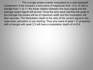
  • 12. For a single phase inverter modulated by a sine-sawtooth comparison, if we compare a sine wave of magnitude from -2 to +2 with a triangle from -1 to +1 the linear relation between the input signal and the average output signal will be lost. Once the sine wave reaches the peak of the transgle the pulses will be of maximum width and the modulation will then saturate. The Modulation depth is the ratio of the current signal to the case when saturation is just starting. Thus sine wave of peak 1.2 compared with a triangle with peak 2.0 will have a modulation depth of m=0.6.
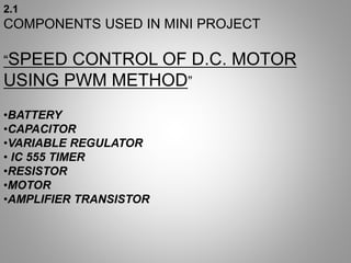
  • 14. 2.1 COMPONENTS USED IN MINI PROJECT “SPEED CONTROL OF D.C. MOTOR USING PWM METHOD” •BATTERY •CAPACITOR •VARIABLE REGULATOR • IC 555 TIMER •RESISTOR •MOTOR •AMPLIFIER TRANSISTOR
  • 16. .DC Motor is a Machine which converts Electrical energy into Mechanical energy. .It takes Electrical energy as input and produces Mechanical rotations of the MOTOR shaft. .DC Motors are widely used in many industrial applications and in day to day life.
  • 17. ADVANTAGES There various advantages are: PWM technique enables greater efficiency of DC Motor. PWM technique improves speed control and reduces power loss. Internal Motor resistance can be easily overcome. The pulses reach full supply voltage which in turn produces more Torque. DISADVANTAGES Increased Complexity. Speed obtained is less than the specified speed due to losses. Speed remains limited.
  • 18. INTRODUCTION TO IC 555 TIMER Introduced by Signetics in 1972, most popular is NE555 by STM electronics and Fairchild Semiconductor. • The 555 timer IC is an integrated circuit (chip) used in a variety of timer, pulse generation, and oscillator applications. • The 555 is used to provide time delays, as an oscillator, and as a flip- flop element. • It gets its name from the three 5k ohm resistors which give the two comparators reference voltage. • Depending on the manufacturer, the standard 555 package includes 25 transistors, 2 diodes and 15 resistors on a silicon chip installed in an 8-PIN DIP (Dual in-line) package. • It is available in low power CMOS type ICM7555 package and 556 Dual Timer (14 pin) with two timer in one IC and 558 which is Quad timer.
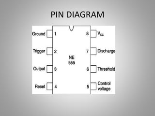
  • 19. PIN DESCRIPTION PIN 1- Ground, The ground pin connects the555 timer to the negative (0v) supply rail. PIN 2-Trigger, when < 1/3 Vcc (active low)this makes the output high (+Vcc). It monitors the discharging of the timingcapacitor in an astable circuit. PIN 3-Output, The output pin can drive any TTL circuit and is capable of sourcing or sinking up to 200mA of current at an output voltage equal to approximately Vcc - 1.5V so small speakers, LEDs or motors can be connected directly to the output. PIN 4-Reset, when less than about 0.7V (active low) this makes the output low (0V), overriding other inputs. When not required it should be connected to +Vcc.
  • 20. PIN 5-Control Voltage, this can be used to adjust the threshold voltage which is set internally to be 2/3 Vcc. Usually this function isnot required and the control input is connected to 0V with a 10nF capacitor to eliminate electrical noise. PIN 6-Threshold, when > 2/3 Vcc (active high)this makes the output low (0V)*. It monitors the charging of the timing capacitor in astable and monostable circuits. PIN 7-Discharge, The discharge pin is connected directly to the Collector of an internal NPN transistor which is used to "discharge" the timing capacitor to ground when the output at pin 3 switches "LOW".PIN 8- Supply +Vcc, This is the power supply pin and for general purpose TTL 555 timers is between 4.5V and 15V (18V Absolute Maximum).
  • 22. 3.CIRCUIT DESIGN .1 “Circuit design of speed control of D.C motor”
  • 23. • 4.2 GOAL • “To explain working of the PWM circuit.” •4.3 BASIC BLOCK DIAGRAM As shown in block diagram there are mainly three blocks: Astable Multivibrator, Monostable Multivibrator and Driving Circuit. Fig. 4.1 Block Diagram
  • 24. The Basic Blocks are explained below: • Astable Multivibrator: This block produce square pulses of same frequency according to time constant RC. These pulses are fed to next block as triggering pulses. • Monostable Multivibrator: This block produces square pulses of variable frequencies. The frequency of output pulse can be varied by changing the value of resistor shown in figure. These pulses are fed to the driving circuit. Driving Circuit: This block provides power required to drive the motor. As the frequency of output pulses of Monostable multivibrator changes, the average voltage supplied to motor changes. Hence, the speed of motor changes
  • 26. •5.1 GOAL “To conclude the work carried out.” •5.2 CONCLUSION •From the project work, following points can be concluded. •It fulfils all the requirements for its application. •The motor responds to the average value of the pulses and not to the individual pulses as the chopper works at high frequency. •Changing the duty-cycle of the pulse by changing the speed of regulator changes the average voltage level. •It is possible to improve overall performance of the motor speed.