Medium access control unit 3-33
4 likes•2,323 views

1) Medium Access Control (MAC) protocols regulate access to shared wireless channels and ensure performance requirements of applications are met. They assemble data into frames, append addressing and error detection, and disassemble received frames. 2) Common MAC protocols include Fixed Assignment (e.g. TDMA), Demand Assignment (e.g. polling), and Random Assignment (e.g. ALOHA, CSMA). Schedule-based MAC protocols avoid contention through resource scheduling while contention-based protocols (e.g. CSMA/CA) allocate resources on demand, risking collisions. 3) The document discusses various MAC protocols for wireless sensor networks and their objectives to minimize energy waste from idle listening, collisions,


Medium access control unit 3-33
- 1. MEDIUM ACCESS CONTROL PROTOCOLS FOR WIRELESS SENSOR NETWORKS 1
- 2. MAC • Shared access of the channel requires the MAC protocol among the sensor nodes • Regulate access to the shared wireless medium • Performance requirements of the underlying application are satisfied • DLL with 2 Layers – LLC – MAC 2
- 3. OSI reference model and data link layer architecture 3
- 4. Basic functions: • Assembly of data into a frame for transmission • Appending a • Header field containing addressing information and • Trailer field for error detection (PHY-DLL-N/W) Contd..4
- 5. Basic functions: • Disassembly of a received frame to – Extract addressing to perform address recognition – Error control information and error detection and recovery • The regulation of access to the shared transmission medium as per the performance requirements of the supported application 5
- 6. MAC • Two main factors Influence aggregate behavior of a distributed MAC – Intelligence of the decision made by the access protocol and – Overhead involved 6
- 8. Delay 1. Delay : Amount of time spent by a data packet in the MAC layer before it is transmitted successfully • Delay depends on – Network traffic load – Design choices of the MAC protocol • For Time-critical applications – MAC protocol should support delay-bound guarantees necessary to meet their QoS requirements Contd.. 8
- 9. Delay • Two types of delay – Probabilistic – Deterministic • Probabilistic delay typically characterized by – Expected value – Variance – Confidence interval Contd.. 9
- 10. Delay • Deterministic delay guarantees – Predictable number of state transitions between message arrival and message transmission – Guarantee an upper bound for the access time – Crucial requirement in a real-time environment Contd.. 10
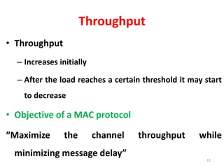
- 11. Throughput 2. Throughput: The rate at which messages are serviced by a communication system • Measured as – Messages per second OR – Bits per second Contd.. 11
- 12. Throughput • Throughput – Increases initially – After the load reaches a certain threshold it may start to decrease • Objective of a MAC protocol “Maximize the channel throughput while minimizing message delay” 12
- 13. Robustness • 3. Robustness : Reliability+ Availability + Dependability • Reflects the degree of the protocol insensitivity to errors and misinformation. Contd.. 13
- 14. Robustness • Robustness address issues such as – Error confinement, – Error detection and masking, – Reconfiguration, and restart Difficult for WSN • Failure of links • Communicating nodes 14
- 15. Scalability 4. Scalability ability of a communications system to meet its performance characteristics regardless of the size of the network or the number of competing nodes Contd.. 15
- 16. Scalability • A common approach to achieve scalability – Avoid relying on globally consistent network states – Localize interactions among the communicating nodes • Hierarchical structures and information aggregation strategies • Grouping sensor nodes into clusters – Allows the design of shared medium access protocols which are highly scalable – Aggregating information 16
- 17. Stability 5. Stability ability of a communications system to handle fluctuations of the traffic load over sustained periods of time A stable MAC protocol handles instantaneous loads exceeding the maximum sustained load (with in maximum capacity of the channel) Contd…17
- 18. Stability • A MAC protocol is stable – If the message waiting time is bounded (delay) and if the throughput does not collapse as the load increases • Load fluctuations + stability is difficult to achieve in WSNs • Approach : Careful scheduling of bursty traffic 18
- 19. Fairness 6. Fairness Allocating channel capacity evenly among the competing communicating nodes without reducing the network throughput • Network is with – Various traffic sources – Different traffic generation patterns – Wide range of QoS requirements. Contd…19
- 20. Fairness • To accommodate heterogeneous resource demands – Assign different weights to reflect their relative resource share • Proportional fairness is then achieved based on the weights assigned Contd…20
- 21. Fairness • Fair resource allocation in wireless networks is difficult to achieve – Global information required to coordinate access to the communication medium – The time-varying characteristics of the wireless links 21
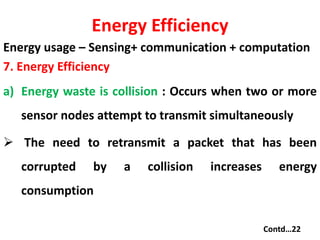
- 22. Energy Efficiency Energy usage – Sensing+ communication + computation 7. Energy Efficiency a) Energy waste is collision : Occurs when two or more sensor nodes attempt to transmit simultaneously The need to retransmit a packet that has been corrupted by a collision increases energy consumption Contd…22
- 23. Energy Efficiency b) Energy waste is idle listening: A sensor node is listening for a traffic that is not sent c) Energy waste is overhearing : Occurs when a sensor node receives packets that are destined to other nodes c) Energy waste is caused by control packet overhead : Control packets to regulate access to the transmission channel A high number of control packets than of data packets delivered indicates low energy efficiency Contd…23
- 24. Energy Efficiency e) Frequent switching between different operation modes may result in significant energy consumption. Solution : – Limiting the number of transitions between sleep and active modes – Energy-efficient link-layer protocols achieve energy savings by controlling the radio – Using comprehensive energy management schemes 24
- 25. Common Protocols • The choice of the MAC method is the major determining factor in the performance of a WSN • Major categories of MAC Protocols – Fixed assignment – Demand assignment – Random assignment 25
- 26. Fixed-Assignment Protocols • Each node is allocated a predetermined fixed amount of the channel resources regardless of current Comm. need • Each node uses its allocated resources without competing with other nodes • Typical protocols – Frequency-division multiple access (FDMA) – Time-division multiple access (TDMA) – Code-division multiple access (CDMA) Spread Spectrum based (FHSS or DSSS) 26
- 27. FDMA, TDMA, AND CDMA 27
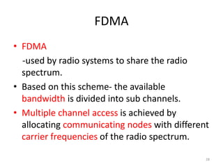
- 28. FDMA • FDMA -used by radio systems to share the radio spectrum. • Based on this scheme- the available bandwidth is divided into sub channels. • Multiple channel access is achieved by allocating communicating nodes with different carrier frequencies of the radio spectrum. 28
- 29. FDMA • The bandwidth of each node’s carrier is constrained within certain limits - no interference /overlap occurs between communicating nodes. *Requires frequency synchronization *Communication is achieved by – having the receiver tune to the channel used by the transmitter. 29
- 30. TDMA • Digital transmission technology • Allows a no of communicating nodes to access a single radio frequency channel without interference. • Achieved by dividing the radio frequency into time slots and then allocating unique time slots to each communicating node. • Nodes takes turns in round robin fashion(transmitting and receiving) • Only one node is using the channel at any given time for the duration of time slot. 30
- 31. CDMA • Spread spectrum based scheme • Allows multiple communicating nodes to transmit simultaneously • Radio frequency modulation technique – radio energy is spread over a much wider bandwidth that that needed for the data rate. • Transmit an information signal by combining it with a noise like signal of much larger bandwidth to generate a wideband signal. • Signal transmitted occupies larger bandwidth than that normally required to transmit the original information. 31
- 32. CDMA • Using wideband noiselike signals makes it hard to detect,intercept or demodulate the original signal. • Uses either FHSS/ DSSS. • Hybrid systems use combination 32
- 33. Demand Assignment Protocols • Improve channel utilization by allocating the capacity of the channel to contending nodes in an optimum or near-optimum fashion • Ignore idle nodes and consider only nodes that are ready to transmit • Polling (master control device and slave node) • Reservation (With reservation messages) 33
- 34. Random Assignment Protocols Random assignment strategies do not exercise any control All backlogged nodes must contend to access the transmission medium Collision occurs when more than one node attempts to transmit simultaneously To deal with collisions, the protocol must include a mechanism to detect collisions 34
- 35. Random Assignment Protocols Pure ALOHA Slotted ALOHA CSMA ( carrier-sense multiple access) CSMA/CD (carrier-sense multiple access with collision detection) CSMA/CA (carrier-sense multiple access with collision avoidance) 35
- 36. ALOHA • A shared communication system like ALOHA requires a method of handling collisions that occur when two or more systems attempt to transmit on the channel at the same time. • In the ALOHA system, a node transmits whenever data is available to send. • If another node transmits at the same time, a collision occurs, and the frames that were transmitted are lost. • However, a node can listen to broadcasts on the medium, even its own, and determine whether the frames were transmitted. 36
- 37. • There are two different versior.s/types of ALOHA: • (i) Pure ALOHA (ii) Slotted ALOHA 37
- 38. Pure ALOHA • In pure ALOHA, the stations transmit frames whenever they have data to send. • When two or more stations transmit simultaneously, there is collision and the frames are destroyed. • In pure ALOHA, whenever any station transmits a frame, it expects the acknowledgement from the receiver. • If acknowledgement is not received within specified time, the station assumes that the frame (or acknowledgement) has been destroyed. • If the frame is destroyed because of collision the station waits for a random amount of time and sends it again. This waiting time must be random otherwise same frames will collide again and again. • Therefore pure ALOHA dictates that when time-out period passes, each station must wait for a random amount of time before resending its frame. This randomness will help avoid more collisions. 38
- 39. PURE ALOHA 39
- 40. ALOHA 40
- 41. 41
- 42. Slotted ALOHA • Slotted ALOHA was invented to improve the efficiency of pure ALOHA as chances of collision in pure ALOHA are very high. • • In slotted ALOHA, the time of the shared channel is divided into discrete intervals called slots. • • The stations can send a frame only at the beginning of the slot and only one frame is sent in each slot. 42
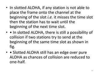
- 43. • In slotted ALOHA, if any station is not able to place the frame onto the channel at the beginning of the slot i.e. it misses the time slot then the station has to wait until the beginning of the next time slot. • • In slotted ALOHA, there is still a possibility of collision if two stations try to send at the beginning of the same time slot as shown in fig. • • Slotted ALOHA still has an edge over pure ALOHA as chances of collision are reduced to one-half. 43
- 44. Pure and Slotted ALOHA 44
- 45. 45
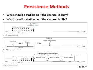
- 46. Persistence Methods • What should a station do if the channel is busy? • What should a station do if the channel is idle? Contd…46
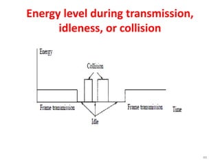
- 47. Contd …47
- 48. CSMA/CD • A station needs to be able to while receive Or transmitting to detect a collision • If no collision, the station receives one signal: its own signal. • If collision, the station receives two signals: its own signal and the signal transmitted by a second station. • The received signals in these two cases must be significantly different. 48
- 49. Energy level during transmission, idleness, or collision 49
- 50. CSMA/CD • The CSMA method does not specify the procedure following a collision. • CSMA/CD augments the algorithm to handle the collision. • A station monitors the medium after it sends a frame to see if the transmission was successful. • If so, the station is finished If there is a collision, the frame is sent again 50
- 51. CSMA/CD 51
- 52. Carrier Sense Multiple Access with Collision Avoidance (CSMA/CA) • Three strategies are used to avoid Collision In CSMA/CA – Interframe Space (IFS) – Contention Window – Acknowledgment 52
- 53. CSMA/CA • Interframe Space (IFS) When an idle channel is found, the station does not send immediately Waits for a period of time called the Interframe space or IFS (Distant station may have already started transmitting) IFS can also be used to define the priority of a station or a frame. 53
- 54. CSMA/CA • Contention Window The contention window is an amount of time divided into slots. A station that is ready to send chooses a random number of slots as its wait time. The number of slots in the window changes according to the binary exponential back-off strategy. set to one slot the first time and then doubles each time the station cannot detect an idle channel after the IFS time. Contd…54
- 55. CSMA/CA The station needs to sense the channel after each time slot If the channel is busy, it just stops the timer and restarts it when the channel sensed as idle. This gives priority to the station with the longest waiting time. • Acknowledgment • Still there may be a collision and data may be corrupted during the transmission • Hence positive acknowledgment and the time-out timer 55
- 56. CSMA/CA 56
- 57. 57
- 58. Problems with CSMA/CA • Referred to as the •Hidden node problem •Exposed node problem 58
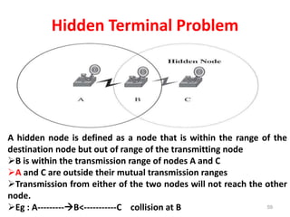
- 59. Hidden Terminal Problem 59 A hidden node is defined as a node that is within the range of the destination node but out of range of the transmitting node B is within the transmission range of nodes A and C A and C are outside their mutual transmission ranges Transmission from either of the two nodes will not reach the other node. Eg : A---------B<-----------C collision at B
- 60. Exposed Terminal Problem • An exposed node is a node that is within the range of the sender but out of the range of the destination • B is within the transmission range of nodes A and C • A and C are outside their mutual transmission ranges • D is within the transmission range of node C. • Eg: B----A and C--D(finds channel busy) 60
- 61. Solutions • 1) Busy-tone approach: Busy-tone signal Not too weak not to be heard by a node within the range of a receiver Not too strong to force more nodes than necessary to suppress their transmissions Advantage : solves both hidden node and exposed node problem Disadvantage: Need Duplex mode (Comm. Complexity) 61
- 62. Solutions • 2) Handshake (Ready to- send (RTS), clear-to-send (CTS)) 62
- 63. Collision avoidance using RTS/CTS handshake 63 Start timer Start timer
- 64. Collision avoidance failure using RTS/CTS handshake 64
- 65. MAC PROTOCOLS FOR WSNs • Conserve energy is the critical issue in the design of scalable and stable MAC layer protocols for WSNs • Factors contribute to energy waste – Idle listening – Packet collisions – Overhearing – Exchange of control and synchronization 65
- 66. MAC for WSN • Two main groups of MAC-layer protocols – Schedule Based – Contention Based • Schedule-based protocols – Deterministic MAC layer protocols – Access to the channel is based on a schedule – Channel access is limited to one sensor node at a time – Pre allocation of resources to individual sensor nodes Contd…66
- 67. MAC for WSN • Contention-based MAC-layer protocols – Avoid pre allocation of resources to individual sensors – A single radio channel is shared by all nodes and allocated on demand – Simultaneous attempts to access the communications medium results in collision • The main objective of contention-based MAC layer protocols – To minimize, rather than completely avoid, the occurrence of collisions – To reduce energy consumption Contd…67
- 68. Schedule-Based Protocols • Schedule-based MAC protocols for WSNs • Regulates access to resources to avoid contention between nodes • Typical resources include – Time – Frequency band – CDMA code Contd…68
- 69. Schedule-Based Protocols • The objective of schedule based – To achieve a high level of energy efficiency (To prolong the network lifetime) – Scalability – Adaptability to changes in • Traffic load • Network topology • Most of the scheduled-based protocols for WSNs use a variant of a TDMA scheme Contd…69
- 70. TDMA Scheme Contd…70 A set of N contiguous slots (N : system parameter, logical frame) Logical frame repeats cyclically over time Sensor nodes are assigned a/set of specific time slots Sensor node operates in each logical frame in the assigned time slot The schedule can be either Fixed Constructed on demand (requirements of sensor nodes and traffic pattern) Hybrid (Structure varies over different time scales and sensor behavior)
- 71. TDMA Scheme Advantages • No collisions • Energy efficient — easily support low duty cycles Disadvantages • Difficult to accommodate node changes • Requires strict time synchronization • Could limit available throughput 71
- 72. Mode of Operation • Based on its assigned schedule, a sensor alternates between two modes of operation: • Active mode • Sleep mode • Active mode: – Sensor uses its assigned slots within a logical frame to transmit and receive data frames – Outside their assigned slots, sensor nodes move into sleep mode • Sleep mode : – Sensor nodes switch their radio transceivers off to conserve energy. 72
- 73. Self-Organizing Medium Access Control for Sensornets (SMACS) • SMACS Enable – Formation of random network topologies – No need of global synchronization among the network nodes • Referred to as non synchronous scheduled communication • No need for costly exchange of global connectivity information or time synchronization. Contd…73
- 74. SMACS • Each node – Regularly execute a neighborhood discovery procedure – Establishes a link to each neighbor discovered – Maintains a TDMA-like frame (superframe) to maintains its own time slot schedules with all its neighbors to communication Contd…74
- 75. SMACS – The length of a superframe is fixed and is divided into smaller frames. – Talk to neighbors in different time slots – Use a hybrid TDMA/FH – Each link consists of a pair of time-slots that operate on fixed frequencies Contd…75
- 76. SMACS – Random wake up schedule during connection phase and nodes sleep during idle time slots. – Nodes tune their radios • To proper frequency channel OR • CDMA code to achieve communication 76
- 77. Bluetooth MAC • Centralized TDMA-based protocol • Bluetooth operates in the 2.45-GHz ISM frequency band • Physical layer is based on a frequency-hopping scheme • Hopping frequency of 1.6 kHz • A set of 79 hop carriers are defined with 1-MHz spacing • Data rate supported is 1 Mbps. Contd…77
- 78. Bluetooth MAC • A group of devices sharing a common channel and called piconet • Access to the channel is regulated using a slotted time-division duplex (TDD) • Master unit controls access to the channel in each piconet • Each channel is divided into 625-ms slots • Each piconet is assigned a unique frequency-hopping pattern determined by the master’s Bluetooth device address (48 bits) and clock. • Master assigns each slave device a unique internal address of 3 bits. Contd…78
- 79. Bluetooth MAC • The master polls the slave devices continuously for communication. • Different piconets use different hopping sequences, and hence guaranteeing their coexistence. • Piconets can be interconnected, via bridge nodes, to form larger ad hoc networks, known as scatter nets. Contd…79
- 80. Operational Modes in Bluetooth • Bluetooth specifies four operational modes: Active Sniff Hold Park • Active mode: – Slave listens for packet transmission from the master. – Checks the address and packet length field of the packet header – If the packet does not contain its own address, the slave sleeps for the duration of the remaining packet transmission. – The intended slave remains active and receives the packet payload in the reserved slot. Contd…80
- 81. Operational Modes in Bluetooth • Sniff mode – Intended to reduce the duty cycle of a slave’s listen activity – A slave in sniff mode listens for the master transmissions only during the specified time slots for any possible transmission to it • Hold mode – A slave goes into the sleep mode for a specified amount of time – Returns to the active mode when the hold time expiresContd…81
- 82. Operational Modes in Bluetooth • Park mode – The slave stays in the sleep state for an unspecified amount of time – The master has to awake the slave explicitly and bring it into the active mode at a future time Contd…82
- 83. Communication in Bluetooth • Four types of communication between nodes within and across piconets: – Intra piconet unicast: • Slave-to-slave communication within a piconet – Intra piconet broadcast • Broadcasting by a slave to all participants within its piconet – Inter piconet unicast • Piconet-to-piconet communications – Inter piconet broadcast • Piconet-to-all scatternet node communications Contd…83
- 84. Intra piconet unicast communication – Slave writes its MAC address in the corresponding field of the data packet – Sets the forward field to 1 and the destination address – Master checks the forward field – The master replaces the MAC address field with its MAC address – Master sends the message to the intended slave device indicated by the destination address Contd…84
- 85. Intra piconet broadcast communication • Slave writes its own MAC address • Sets the forward field to 1 and the destination address to 000 • The master notices that the forward field is set • Master replaces the MAC address with its own address • Sends the message to all nodes in its piconet Contd…85
- 86. Inter piconet unicast communication – Source device sends the data packet with • Own MAC address • Sets the forward field to 1 • Broadcast field to 1 • Destination address to the relay of the next piconet. – Source device sets the routing vector field (RVF) of the packet (path to the targeted destination) Contd..86
- 87. Inter piconet unicast communication – The RVF is a sequence of tuples of the form (LocId, Mac_Addr) • LocId represents the identity of the local master • Mac_Addr its corresponding piconet MAC address. – The master forwards it to the relay node – The relay extracts from the RVF the local identity and the MAC address of the master – The process is repeated till the destination device has been reached. Contd…87
- 88. Inter piconet broadcast communication Source device creates a packet containing its own MAC address Sets the forward and broadcast fields of the packet to 1 Sets the destination address to 000 The packet is sent to the master The master sends the packet to all the slaves within its piconet, including relay nodes. Relay node receives the broadcast packet and forwards it to all masters connected, except the one from which it came.Contd…88
- 89. Low-Energy Adaptive Clustering Hierarchy (LEACH) • A hierarchical approach and organizes nodes into clusters • Cluster head rotation • TDMA within each cluster – Static TDMA frame • Node only talks to cluster head • CDMA between clusters • Only cluster head talks to base station Contd…89
- 91. LEACH • Base station send out synchronization pulses to the all the nodes • Communication between a node and its cluster head are achieved using direct-sequence spread spectrum (DSSS) • Each cluster is assigned a unique spreading code • Spreading codes are assigned to cluster heads on a first-in, first-served basis • Nodes adjust their transmit powers to reduce interference with nearby clusters • Advantages of TDMA: – Cluster nodes turn off their radio components till its allocated time slots. Contd…91
- 92. LEACH • Cluster head aggregates the data (of cluster nodes) before sending them to the base station. • The communication between a cluster head and a base station is achieved using fixed spreading code and CSMA. • Cluster head delays the data transmission until the channel becomes idle. Contd…92
- 93. Advantages of LEACH • Contention-free, eliminate energy waste caused by collisions. • Nodes turn their radios during slots to data transmission or received. • Sensor node can turn off its radio, thereby avoiding overhearing – Extend the network lifetime significantly. Contd…93
- 94. Disadvantages of LEACH • Hierarchical structure restricts nodes to communicate only with their cluster head. • Peer-to-peer communication cannot be supported because of sleep mode. • Achieving time synchronization among distributed sensor nodes is difficult and costly. Contd…94
- 95. Disadvantages of LEACH • Schedule-based schemes also require additional mechanisms such as FDMA or CDMA to overcome inter cluster communications and interference. • TDMA-based MAC-layer protocols – limited scalability – Not easily adaptable to node mobility and changes in network traffic and topology. – As nodes join or leave a cluster, the frame length as well as the slot assignment must be adjusted. – Frequent changes may be expensive or slow to take effect. Contd…95
- 96. Random Access-Based Protocols • No coordination among the nodes accessing the channel • Colliding nodes back off for a random duration of time • Enhancement of protocols with – Collision avoidance and – Request-to-send (RTS) and clear-to-send (CTS) Make them more robust to the hidden terminal problem 96
- 97. Random Access-Based Protocols • The energy efficiency of contention-based MAC-layer protocols remains low due to – Collisions – Idle listening – Overhearing – Excessive control overhead • Random access MAC-layer protocols focused on reducing energy waste 97
- 98. Power Aware Multiaccess protocol with Signaling (PAMAS) • Avoids overhearing among neighboring nodes by using a separate signaling channel • The protocol combines use of – Busy tone and – RTS and CTS packets • Two channels – Data – Control • Upon wakeup, probe control channel for activity related to destination node 98
- 99. 99 PAMAS and Channel Probing • Neighbor answer probe(busy tone) ? Yes, go back to sleep • Probing eliminated interference with transmission in data channel • Nodes currently not actively transmitting / receiving packets turn off their radio transceivers. • Disadvantages – More complex to implement (two channels) – PAMAS does not reduce idle listening
- 100. Timeout-MAC (T-MAC) • Nodes alternate between sleep and wake-up modes for predetermined time • Each node wakes up periodically to communicate with its neighbors • A node keeps listening and potentially transmitting as long as it is in the active period 100
- 101. Timeout-MAC (T-MAC) • Active events include – Hearing of a periodic frame timer – Reception of data over the radio – Sensing of an activity such as collision on the channel, – End of transmission of a node’s own data packet or acknowledgment – End of a neighboring node’s data exchange, (determined through overhearing of prior RTS and CTS packets.) • At the end of the active period, the node goes into sleep mode. 101
- 102. Timeout-MAC (T-MAC) • Contention-based MAC-layer protocol designed for applications characterized by – low message rate – low sensitivity to latency (Support burst traffic) • T-MAC nodes use RTS, CTS, and acknowledgment packets to communicate with each other. (Avoid collision and ensure reliable transmission) • Protocol uses an adaptive duty cycle to – Reduce energy consumption and – Adapt to traffic load variations 102
- 103. Timeout-MAC (T-MAC) • Reduce idle listening by transmitting all messages in bursts of variable length • Protocol dynamically determines the optimal length of the active time, based on current load. • Messages between active times must be buffered • Buffer capacity determines an upper bound on the maximum frame time. 103
- 104. Sparse Topology and Energy Management (STEM) Protocol • The trades latency for energy efficiency • Use two radio channels – Data radio channel – Wake-up radio channel. • STEM is known as a pseudo asynchronous scheduled scheme • A node turns off its data radio channel until communication with another node is desired • Node begins transmitting on the wake-up radio channel when it has data to transmit • The wake-up signal channel acts like a paging signal 104
- 105. Sparse Topology and Energy Management (STEM) Protocol • The transmission of this signal lasts long enough to ensure that all neighboring nodes are paged. • A node can also be awakened to receive all of its pending packets before going into the sleep mode again. • The STEM protocol – Can be used in conjunction with other MAC-layer scheduling protocols – Effective only in network environments where events do not happen very frequently. – If events occur frequently, the energy wasted by continuously transmitting wake-up signals 105
- 106. B-MAC - Berkeley MAC • B-MAC’s Goals: – Low power operation – Effective collision avoidance – Simple implementation (small code) – Efficient at both low and high data rates – Reconfigurable by upper layers – Tolerant to changes on the network – Scalable to large number of nodes