EMBEDDED SYSTEMS SYBSC IT SEM IV UNIT V Embedded Systems Integrated Development Environment
Download as PPTX, PDF0 likes1,457 views

The document provides an overview of integrated development environments (IDEs) used in embedded systems, detailing their components, types, file outputs from cross-compilation, and the development life cycle. It covers the essential tools for debugging, such as simulators and emulators, and outlines the phases of embedded product development, including analysis, design, development, and support. Additionally, it discusses the objectives and need for an embedded development life cycle (EDLC) to ensure quality, productivity, and effective project management.


EMBEDDED SYSTEMS SYBSC IT SEM IV UNIT V Embedded Systems Integrated Development Environment
- 1. EMBEDDED SYSTEMS INTEGRATED DEVELOPMENT ENVIRONMENT UNIT V
- 2. EMBEDDED IDE • Integrated Development Environment with respect to embedded system IDE stands for an Integrated Environment for developing and debugging the target processor specific embedded software. • IDE is a software package which contains: – 1. Text Editor(Source Code Editor) – 2. Cross Compiler(For Cross platform development and complier for the same platform development) 3. Linker and debugger. • Some IDEs may provide an interface to an emulator or device programmer. • IDEs are used in embedded firmware development
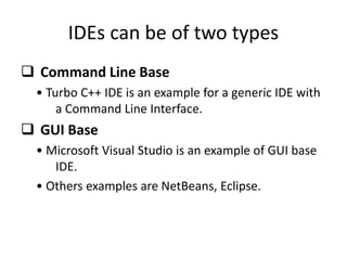
- 3. IDEs can be of two types Command Line Base • Turbo C++ IDE is an example for a generic IDE with a Command Line Interface. GUI Base • Microsoft Visual Studio is an example of GUI base IDE. • Others examples are NetBeans, Eclipse.
- 4. TYPES OF FILE GENERATED ON CROSS COMPILATION • List file .lst (Page Header, Command Line, .Source Code, Assembly listing, Symbol listing , Module Information, Warnings and Errors) • Hex file .hex • Preprocessor output file (Macros and preprocessor directive. ) • Map file .map (Page Header, Command Line, CPU Details , Input Modules, Memory Map, Symbol Table, Warnings and Errors ) • Obj file .obj
- 5. List File(.lst) • Listing file is generated during the cross-compilation process. • It contains an information about the cross compilation process like cross compiler details, formatted source text(‘C’ code), assembly code generated from the source file, symbol tables, errors and warnings detected during the cross-compilation process. • The list file contain the following sections: – Page Header – It indicates the compiler version name, source file name, Date, Page No. – Command Line – It represents the entire command line that was used for invoking the compiler – Source Code – It contains source code along with line numbers – Assembly listing – It contains the assembly code generated by compiler for even given ‘C’ code. – Symbol listing – It contains symbolic information about the various symbols present in the cross compiled source file. – Eg: NAME, TYPE, SFR, SIZE. – Module Information – The module information provides the size of initialized and un-initialized memory areas defined by the source file. – Warnings and Errors – Warnings and Errors section of list file records the errors encountered or any statement that may create issues in application(Warnings), during cross compilation.
- 6. Preprocessor Output File • It contains preprocessor output for preprocessor instructions used in the source file. • This file is used for verifying the operation of Macros and preprocessor directive.
- 7. Object File(.OBJ File) • Cross-compiling each source module converts the Embedded C/Assembly instructions and other directives present in the module to an object(.OBJ file)
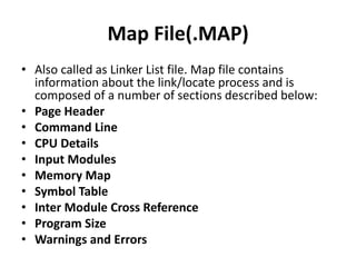
- 8. Map File(.MAP) • Also called as Linker List file. Map file contains information about the link/locate process and is composed of a number of sections described below: • Page Header • Command Line • CPU Details • Input Modules • Memory Map • Symbol Table • Inter Module Cross Reference • Program Size • Warnings and Errors
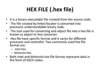
- 9. HEX FILE (.hex file) • It is a binary executable file created from the source code. • The file created by linker/locater is converted into processor understandable binary code. • The tool used for converting and object file into a hex file is known as object to Hex converter. • Hex file have specific format and it varies for different processor and controller. Two commonly used hex file format are: – Intel Hex – Motorola Hex. • Both Intel and Motorola hex file format represent data in the form of ASCII codes.
- 10. DISASSEMBLER/ DECOMIPILER • A Disassembler/ Decomipiler is a reverse engineering tool. • Reverse Engineering is used in embedded system to find out the secret behind the working of a proprietary product. • A DISASSEMBLER is a utility program which converts machine codes into target processor specific assembly code/instruction. • The process of converting machine codes to assembly code is called disassembling. • A DECOMIPILER is a utility program for translating machine codes into corresponding high level language instruction. • A decompiler performs the reverse operation of a compiler/cross-compiler.
- 11. SIMULATOR • Simulators are used for embedded firmware debugging. • Simulator simulates the target hardware, while the code execution can be inspected. • Simulators have the following characteristics which make them very much favorable: – Purely software based – No need of target system (hardware) – Support only for basic operations – Cannot Support or lack real time behavior
- 12. SIMULATOR- Advantages 1. Simple and straight forward. Simulators are a software utility with assumptions about the underlying hardware. So it only requires concentrating on debugging of the code, hence straight forward. 2. No Hardware Simulators are purely software oriented. • The IDE simulates the target CPU. The user needs to know only about the target specific details like memory map of various devices. • Since no hardware is required the code can be written and tested even before the hardware prototype is ready thus saving development time 3. Simulation options Simulators provide various simulation options like I/O peripherals or CRO or Logic analyzers. Simulators I/O support can be used to edit values for I/O registers. 4. Simulation of abnormal conditions Using simulator the code can be tested for any desired value. This helps to study the code behavior in abnormal conditions without actually testing it on the hardware
- 13. SIMULATOR- Disadvantages • Lack of real time behavior • A simulator assumes the ideal condition for code execution. • Hence the developer may not be able to debug the code under all possible combinations of input. • The results obtained in simulation may deviate from actual results on target hardware. • Lack of real timeliness • The I/O condition in hardware is unpredictable. So the output of simulation is usually under ideal condition and hence lacks timeliness.
- 14. FIRMWARE DEBUGGING • Debugging in embedded application is the process of diagnosing the firmware execution, monitoring the target processor’s registers and memory while the firmware is running and checking the signals on various buses of hardware. • Debugging is classified into Hardware Debugging and Firmware Debugging. • Hardware Debugging deals with debugging the various aspects of hardware involved in the embedded system. • The various tools used for hard ware debugging are Multimeter, CRO, Logic Analyzers and Function Generators. • Firmware Debugging involves inspecting the code, its execution flow, changes to different registers on code execution. • It is done to find out the bugs or errors in code which produces unexpected behavior in the system. • There is a wide variety of firmware debugging techniques available that have advanced from basic to advanced. • Some to the tools used are Simulators and Emulators.
- 15. Emulators • The terms simulators and emulators are very confusing but their basic functionality is the same i.e. to debug the code. There is a difference in which this is achieved by both the tools. • A simulator is a utility program that duplicates the target CPU and simulates the features and instructions supported by target CPU • Whereas an Emulator is a self contained hardware device which emulates the target CPU. • The Emulator hardware contains the necessary emulation logic and is connected to the debugging application that runs on the host PC. • The Simulator ‘simulates’ while the Emulator ‘emulates’
- 16. EMBEDDED PRODUCT DEVELOPMENT LIFE CYCLE (EDLC) • EDLC is Embedded Product Development Life Cycle • It is an Analysis – Design – Implementation based problem solving approach for embedded systems development. • There are three phases to Product development: – Analysis involves understanding what product needs to be developed – Design involves what approach to be used to build the product – Implementation is developing the product by realizing the design.
- 17. Need for EDLC • EDLC is essential for understanding the scope and complexity of the work involved in embedded systems development • It can be used in any developing any embedded product • EDLC defines the interaction and activities among various groups of a product development phase. – Example:-project management, system design
- 18. Objectives of EDLC • EDLC has three primary objectives are: • Ensure that high quality products are delivered to user – Quality in any product development is Return On Investment achieved by the product – The expenses incurred for developing the product the product are:- – Initial investment – Developer recruiting – Training – Infrastructure requirement related
- 19. Objectives of EDLC • EDLC has three primary objectives are: • Risk minimization defect prevention in product development through project management – In which required for product development ‘loose’ or ‘tight’ project management – ‘project management is essential for ’ predictability co-ordination and risk minimization – Resource allocation is critical and it is having a direct impact on investment – Example:- Microsoft @ Project Tool
- 20. Objectives of EDLC • EDLC has three primary objectives are: • Maximize the productivity – Productivity is a measure of efficiency as well as Return On Investment – This productivity measurement is based on total manpower efficiency – Productivity in which when product is increased then investment is fall down – Saving manpower
- 21. DIFFERENT PHASES OF EDLC
- 22. Need • The need may come from an individual or from the public or from a company. • ‘Need’ should be articulated to initiate the Development Life Cycle; a ‘Concept Proposal’ is prepared which is reviewed by the senior management for approval. • Need can be visualized in any one of the following three needs: – New or Custom Product Development. – Product Re-engineering. – Product Maintenance.
- 23. Conceptualization • Defines the scope of concept, performs cost benefit analysis and feasibility study and prepare project management and risk management plans. • The following activities performed during this phase: – Feasibility Study : Examine the need and suggest possible solutions. – Cost Benefit Analysis (CBA): Revealing and assessing the total development cost and profit expected from the product. – Product Scope: Deals with the activities involved in the product to be made. – Planning Activities: Requires various plans to be developed first before development like Resource Planning & Risk management Plans. – Analysis – The product is defined in detail with respect to the inputs, processes, outputs, and interfaces at a functional level.
- 24. The various activities performed during this phase (Conceptualization) • Analysis and Documentations: This activity consolidates the business needs of the product under development. • Requirements that need to be addressed.. Functional Capabilities like performance Operational and non-operational quality attribute Product external interface requirements Data requirements/User manuals Operational requirements Maintenance requirements General assumptions
- 25. The various activities performed during this phase (Conceptualization) • Defining Test Plan and Procedures: The various type of testing performed in a product development are: • Unit testing – Testing Individual modules • Integration testing – Testing a group of modules for required functionality • System testing- Testing functional aspects or functional requirements of the product after integration • User acceptance testing- Testing the product to meet the end user requirements.
- 26. Design • The design phase identifies application environment and creates an overall architecture for the product. • It starts with the Preliminary Design. It establishes the top level architecture for the product. On completion it resembles a ‘black box’ that defines only the inputs and outputs. The final product is called Preliminary Design Document (PDD). • Once the PDD is accepted by the End User the next task is to create the ‘Detailed Design’. • It encompasses the Operations manual design, Maintenance Manual Design and Product Training material Design and is together called the ‘Detailed Design Document’.
- 27. Development and Testing • Development phase transforms the design into a realizable product. • The detailed specification generated during the design phase is translated into hardware and firmware. • The Testing phase can be divided into independent testing of firmware and hardware that is: – Unit testing – Integration testing – System testing – User acceptance testing
- 28. Deployment • Deployment is the process of launching the first fully functional model of the product in the market. It is also known as First Customer Shipping (FCS). • Tasks performed during this phase are: – Notification of Product Deployment: Tasks performed here include: – Deployment schedule – Brief description about the product – Targeted end user – Extra features supported – Product support information – Execution of training plan – Proper training should be given to the end user top get them acquainted with the new product. – Product installation – Install the product as per the installation document to ensure that it is fully functional. – Product post Implementation Review – After the product launch, a post implementation review is done to test the success of the product.
- 29. Support • The support phase deals with the operational and maintenance of the product in the production environment. • Bugs in the product may be observed and reported. • The support phase ensures that the product meets the user needs and it continues functioning in the production environment. • Activities involved under support are – Setting up of a dedicated support wing: Involves providing 24 x 7 supports for the product after it is launched. – Identify Bugs and Areas of Improvement: Identify bugs and take measures to eliminate them. – Upgrades – Deals with the development of upgrades (new versions) for the product which is already present in the market. – Retirement/Disposal – The retirement/disposal of the product is a gradual process. – The disposal of a product is essential due to the following reasons • Rapid technology advancement • Increased user needs
- 30. ELDC APPROACHES • Following are some of the different types of approaches that can be used to model embedded products. – Waterfall or Linear Model – Iterative/ Incremental or Fountain Model – Prototyping Model – Spiral Model
- 31. END OF Syllabus