


1.1. SOC AND MULTICORE ARCHITECTURES FOR EMBEDDED SYSTEMS (2).pdf
- 1. SOC AND MULTICORE ARCHITECTURES FOR EMBEDDED SYSTEMS
- 2. SoCs for embedded systems. Definition. System: set of components needed to perform a function Mix of hardware + software + … Embedded: Main function not computing, but monitorization and/or control. Usually not autonomous Interfaces to the real world Usually: Computer inside a bigger system Designed for a specific purpose Submitted to application specific constrains Adapted from Pierre Boulet - DaRTprojetc team
- 3. SoCs for embedded systems. Examples. very small electronic tags smartcards microcontrollers washing machine, microwave oven, ... computer peripherals keyboard hard drive controller more complex controllers digital camera automotive air bags, ABS, ... ESB, engine control, ... communications mobile phones network routers, modems software radio multimedia set-top boxes cable, satellite TV HDTV, DVD players video games radar, sonar Adapted from Pierre Boulet - DaRTprojetc team
- 4. SoCs for embedded systems. Market. huge market estimation 2011 (IDG News Service) : US$1 trillion estimation 2015 (IDG News Service) : US$2 trillion Will double in four years!!!! number of HW and SW developers increases becomes more important than general purpose computing number of units already number of developpers in a few years Strategic sector for NATO (see 1.6, 1.18) Adapted from Pierre Boulet - DaRTprojetc team Just have to observe the popularization of embedded platforms for consumer (zero- knowledge) markets: • Arduino • Raspberry Pi • Parallella $99 supercomputer • Cubox-i Mini-PC • …
- 5. SoCs for embedded systems. Complexity. Design productivity gap: While designer productivity has grown at an impressive rate over the past decades, the rate of improvement has not kept pace with chip capacity 10,000 1,000 100 10 1 0.1 0.01 0.001 Logic transistors per chip (in millions) 100,000 10,000 1000 100 10 1 0.1 0.01 Productivity (K) Trans./Staff-Mo. IC capacity productivity Gap
- 6. Design productivity gap 1981 leading edge chip required 100 designer months 10,000 transistors / 100 transistors/month 2002 leading edge chip requires 30,000 designer months 150,000,000 / 5000 transistors/month Designer cost increase from $1M to $300M 10,000 1,000 100 10 1 0.1 0.01 0.001 Logic transistors per chip (in millions) 100,000 10,000 1000 100 10 1 0.1 0.01 Productivity (K) Trans./Staff-Mo. IC capacity productivity Gap
- 7. The mythical man-month The situation is even worse than the productivity gap indicates In theory, adding designers to team reduces project completion time In reality, productivity per designer decreases due to complexities of team management and communication In the software community, known as “the mythical man-month” (Brooks 1975) At some point, can actually lengthen project completion time! (“Too many cooks”) 10 20 30 40 0 10000 20000 30000 40000 50000 60000 43 24 19 16 15 16 18 23 Team Individual Months until completion Number of designers • 1M transistors, 1 designer=5000 trans/month • Each additional designer reduces for 100 trans/month • So 2 designers produce 4900 trans/month each
- 8. SoCs for embedded systems. Complexity. Adapted from Pierre Boulet - DaRTprojetc team
- 9. Programming Models Software development: the software engineer is aided by both programming techniques and a variety of hardware processing platforms. Based on the performance and programmability constraints of the system, the software engineer is tasked with determining the best implementation platform to get a project to market. Initially, improving the runtime of software was based on two central concepts: increasing processor clock frequency and using specialized processors. For many years, it was common practice to wait a year for the next generation processor as a way to speed up execution. For a large set of applications, incremental speedup through processor clock frequency is not enough to deliver a viable product to market. For this type of application, the specialized processor was created. There are many kinds of specialized processors: microcontroller unit (MCU), digital signal processor (DSP), and graphics processing unit (GPU), all of which are capable of executing an algorithm written in a high-level language, such as C, and have function-specific accelerators to improve the execution of their target software applications. Therefore, regarding where to run an algorithm, there is an increasing focus on parallelization and concurrency.
- 10. The case for SOCs With the recent paradigm shift in the design of standard and specialized processors, both types of processors stopped relying on clock frequency increases for program speedup and added more processing cores per chip. Multicore processors put program parallelization at the forefront of techniques used to boost software performance. The software engineer must now structure algorithms in a way that leads to efficient parallelization for performance. The techniques required in algorithm design use the same base elements of FPGA (hardware) design. The main difference between an FPGA and a processor is the programming model. What is more: FPGAs an traditional GPPs will be closely coupled in the future!!!! (see side notes: 1.7, 1.8, 1.9, 1.17)
- 11. The case for SOCs The requirements of an embedded solution are very different from general purpose systems (and application-specific servers, such as video servers): compactness, low-cost, low- power, pin-count, packaging, short time-to-market are among the key considerations. In embedded applications, multicore and SoC architectures offer better solutions for this new requirements: Multi-core design is one of the most important solutions for management of system power and the energy efficiency of the system. The system is now divided in power domains and power switches are used to cut off power supply to inactive sub-systems. IP core reuse and platform oriented design, including the use of standard interfaces (buses) are the other key factors in reducing design complexity and increasing testability, what highly reduces time-to-market.
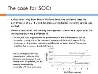
- 12. The case for SOCs A simulation study from Sandia National Labs was published after the performance of 8-, 16-, and 32-processor multiprocessor architectures was studied. Memory bandwidth and memory management schemes are reported to be limiting factors in the performance. In fact, the study suggests that the performance of the multiprocessors can be expected to degrade as the number of processors is increased beyond 8. For example, a 16-processor machine would behave no better than a 2-processor machine due to memory bandwidth issues. The use of stacked memories (memories stacked in the third dimension over processors) was seen to avert this problem, but the speedup increases only marginally with more processors.
- 13. The case for SOCs So, a large number of identical processors on a single chip may not per se result in a good solution for real problems. The best architecture for the application may require a heterogeneous processor architecture and interconnect architecture evolved through careful analysis. At the same time, the development cost and the turn-around time may be unacceptable. economy will limit the semiconductor industry before the end of Moore’s law today design time 30% design 70% verification/test
- 14. Simulation speed Relative speeds of different types of simulation/emulation 10,000,000 gate-level HDL simulation register-transfer-level HDL simulation cycle-accurate simulation instruction-set simulation throughput model hardware emulation FPGA 1 day 1 hour 4 days 1 10 100 1000 10000 100,000 1,000,000 IC 1.4 months 1.2 years 12 years >1 lifetime 1 millennium 1 hour actual execution of SOC = 1.2 years instruction-set simulation = 10,000,000 hours gate-level simulation
- 15. The case for SOCs So, today, the trend is to create “platforms” for classes of applications (video, communications, …). Complex SoCs, based on modular, heterogeneous architectures, that include a mixture of pre-designed pre-verified IP cores and customized (application specific) accelerator modules using common an well standardized communication interfaces, are nowadays the most promising methodology to implement the next generation embedded computers. Including wearable computing, internet of things, etc. We will discuss in detail most of this trends in following chapters: IP core-based design, platform based SoC, reuse-oriented design, ESL (Electronic System Level) design tools, HW/SW codesign methodologies and tools,…
- 16. The System on a Chip Concept A system-on-chip architecture combines one or more (RISC) microprocessors, an on-chip bus system, several dedicated coprocessors, and on-chip memory, all on a single chip. An SoC architecture provides general-purpose computing capabilities along with a few highly specialized functions, adapted to a particular design domain (what targets naturally to embedded systems).
- 17. The System on a Chip Concept A particular configuration of the elements of a SoC is also called a platform. Just like a personal computer is a platform for general-purpose computing, a system-on-chip is a platform for domain specialized computing (mobile telephony, video processing, or high-speed networking). The set of applications in the video-processing domain for example could include image transcoding, image compression and decompression, image color transformations, and so forth. The specialization of the platform ensures higher processing efficiency compared to general-purpose solutions, and/or lower power consumption. The flexibility of the platform ensures that it is a reusable solution that works over multiple applications. As a result, the design cost-per- application decreases, applications can be developed faster, and the SoC itself becomes cheaper because it can be manufactured for a larger market.
- 18. Side note: SoCs examples We will focus on Smartphone and Tablet (as the most “cool”) markets but same tendencies and technologies apply for other markets (communications, …). OMAP (TI). Snapdragon (Qualcomn). TMxx (MediaTex). Tegra 4 (nvidia). Exynos (Samsung). Ax (Apple).
- 19. Side note: SoCs ex. (ARM) http://www.arm.com/markets/ Provides two basic types of licenses (http://www.anandtech.com/show/7112/the- arm-diaries-part-1-how-arms-business-model-works): Processor: involves implementing an ARM designed CPU core (in own or third party foundry). Following are examples of integration of ARM cores into custom SoC: Nvidia Tegra 4 (paired with his own GPU), Samsung Apple (before A6). Architecture: creation of an ARM ISA (Instruction Set Architecture) compatible CPU core. Apple (from A6 and beyond), Qualcomm (Snapdragon – Krait400).
- 20. Side note: SoCs ex. (ARM) http://www.arm.com/markets/
- 21. Side note: SoCs ex. (ARM) Also expanding to server market. Example: HP Moonshot, a new web server architecture. Could we see soon ARM based supercomputers on the Top 500??? (see side notes: 1.9, 1.14, 1.15)
- 22. Side note: SoCs ex. (TI’s OMAP) OMAP Platform: OMAP (Open Multimedia Application Platform) is a solution intended primarily for mobile wireless communications and next generation embedded devices. OMAP makes use of an embedded ARM processor core and a Texas Instruments TMS320C55X or TMS320C64X DSP core. OMAP provides support for both 2G and 3G wireless applications.
- 23. Side note: SoCs ex. (TI’s OMAP) Modem layer 2/3 protocols Radio resource management Short message services (SMS) Man-machine interface Low level operating system functions Modem layer 1 protocols Speech coding/decoding Channel coding/decoding Channel equalization Demodulation Encryption Applications such as echo cancellation, noise suppression, and speech recognition. ARM is intended for the following functions: 2G architecture uses the C54X DSP core which is intended for “user interface”
- 24. Side note: SoCs ex. (TI’s OMAP) By assigning a task to either of the two processors that gives the best power-performance product, the OMAP prolongs battery life 2 o 3 times. Several design techniques are employed to reduce power, including clock gating to power off subsystems when not used. The ARM processor and the DSP communicate with each other through a set of mailboxes. When the ARM processor, which acts as a master, has to dispatch a task to the DSP, it writes a message in the MPU2DSP mailbox. When the DSP completes a task, it places a message in the DSP2MPU mailbox. Since a high-performance graphical display system is a key requirement in 3G wireless applications, OMAP provides a dedicated DMA channel for the LCD controller.
- 25. Side note: SoCs ex. (TI’s OMAP) http://androidandme.com/2012/09/news/texas-instruments-to-exit-omap- from-smartphones-and-tablets/ Today Texas Instruments announced it would “shift its wireless investment focus from products like smartphones to a broader market including industrial clients like carmakers,” a move that sent their shares down 3 percent. TI said they would continue to support their current customers, but they will not invest in supporting its customers future roadmap for tablets and smartphones to the same degree as before. “TI made it very clear they no longer want to be in the business of providing application processors for smartphones or tablets,” said Longbow Research analyst JoAnne Feeney. “What remains uncertain is for how long they’ll support customers.” This move likely means we will not be seeing Android devices based on TI’s upcoming OMAP5. This dual- core Cortex-A15 chip was slated to launch early next year, but we don’t see many manufacturers going forward with the platform if TI will not support it long term. OMAP4 was featured in some pretty high profile devices like the Motorola Droid, Samsung Galaxy Nexus and Amazon Kindle Fire tablets, but TI was facing increased competition from many larger companies. Executives from TI said they were looking for a more stable line of business, and the mobile application processor business is very hits driven. If OMAP5 was having trouble racking up design wins, it could have accelerated TI’s decision to focus on other investments. We are all for competition among the mobile semiconductor companies, so we will be sad to see TI moving on. At least we still have Qualcomm, Samsung, NVIDIA and now Intel to keep things exciting.
- 26. Side note: SoCs ex. (Qualcomn’s Snapdragon) http://www.qualcomm.com/snapdragon/smartphones http://www.qualcomm.com/snapdragon/processors/800-600-400-200/specs http://shop.intrinsyc.com/products/snapdragon-800-series-apq8074-based-dragonboard-development- kit-1
- 27. Side note: SoCs ex. (Qualcomn’s Snapdragon) Qualcomm se ríe sin disimulo de los chips octa-core de MediaTek (engadget.com, 28/08/2013) http://www.youtube.com/watch?feature=player_embedded&v=qdauwqh msas “La gran diferencia entre los SoC tope de gama de Qualcomm y los de MediaTek reside en que los primeros utilizan arquitecturas basadas en Krait 300 y 400 (Snapdragon 600 y 800 respectivamente), mientras que los segundos utilizan una batería de ocho "antiguos" núcleos Cortex-A7 funcionando a todo trapo. Qualcomm afirma que esta combinación no solo ofrece un rendimiento parejo al número de cores, sino que además están vastamente desaprovechados, algo que ilustra señalando que 17 de las 20 aplicaciones más populares en China solo utilizan dos núcleos.” See side notes: 1.11
- 28. Side note: SoCs ex. (MediaTek’s MTxx) http://www.mediatek.com/_en/Event/201307_TrueOctaCore/tureOcta.php http://www.mediatek.com/_en/01_products/04_pro.php?sn=1088
- 29. Side note: SoCs ex. (MediaTek’s MTxx) See side notes: 1.13
- 30. Side note: SoCs ex. (nvidia’s Tegra 4) http://www.nvidia.es/object/tegra-4-processor-es.html http://www.nvidia.es/object/tegra-superphones-es.html
- 31. Side note: SoCs ex. (Samsung’s Exynos) Exynos 5 Octa: Heterogeneous Multi-Processing Capability http://www.samsung.com/global/business/semiconductor/minisite/Exynos/blog_Exynos_5 _Octa_Heterogeneous_Multi_Processing_Capability.html (10/09/2013) “ARM® big.LITTLE technology. In the Exynos 5 Octa, eight CPU cores are responsible for everything from browsing the web to playing your favorite game on your 5 Octa-powered mobile device. Four "big" 1.8GHz ARM®Cortex™-A15 cores handle intensive tasks like graphically rich gaming or HD video playback. Less intensive tasks like e-mail or text functions are tackled by four "LITTLE" 1.3GHz Cortex™-A7 cores. By dividing and conquering tasks and assigning them to the proper CPU cores, big.LITTLE technology maximizes performance while minimizing power loss.” Hardkernel's ODROID-XU: First Exynos 5 Octa Development Board http://www.samsung.com/global/business/semiconductor/minisite/Exynos/blog_Hardkern els_ODROID-XU_First_Exynos_5_Octa_Development_Board.html See side notes: 1.10, 1.11
- 32. Side note: SoCs ex. (Apple’s Ax) A7 SoC: ???????????????????????????? evolution of Apple’s own Swift (A6) architecture. Two ARM-based GP cores, x64, plus….. Running at 1,3GHz. Probably built on Samsung’s 28nm HK+MG process. M7 core: main sensors controller. http://www.eetimes.com/document.asp?doc_id=1319563 “Tim Cook sobre la integración de hardware y software: "Todo el mundo está intentando adoptar la estrategia de Apple”“ (19/09/2013) Google Motorola Microsoft Nokia To be continued….
- 33. Side note: SoCs ex. (Microsoft’s Cell) Xbox One SoC Evolution of Cell processor. 28nm (TSMC), 363mm2 (5000Mtr, 3x Intel’s Haswell) 8 core CPU (AMD's Kaveri APUs), x64, 16,GHz, 4MB cache L2 8GB DDR3 RAM 12 core GPU Audio codec video codecs Kinect contr…
- 34. Side note: SoCs ex. (Microsoft’s Cell) Xbox One SoC http://www.tomshardware.com/news/xbox-one-processor-jaguar-apu-huma,24035.html
- 35. Considerations on power consumtion Power consumption: Remember: the empirical relationship between power and clock frequency for CMOS circuits is CVdd 2f + IoffVdd The dynamic power of a VLSI system grows linearly with the frequency of operation and quadratically with the operating voltage. Static power dissipation due to leakage currents in the transistor has different components that increase linearly and as the cube of the operating voltage. Thus, although reducing the voltage of operation can result in significant reduction in power, it can also negatively impact the frequency of operation. The selection of operating voltage and frequency of operation must consider both power and performance. Turning off the clock for a subsystem is a way to cut down the dynamic power dissipation in the sub-system. Powering off a sub-system helps us cut down the static as well as dynamic power that would otherwise be wasted.
- 36. Considerations on power consumtion Power comsumption: Consider a sub-system S that must provide a performance of T time units per operation. Since the switching speed of transistors depends directly on the voltage of operation, building a circuit that implements S may require us to operate the circuit at a higher voltage V , resulting in higher power dissipation. We may be able to use the parallelism in the functionality of the sub-system to break it down into two sub-systems S′ and S′′. The circuits that implement S′ and S′′ are roughly half in size and have a critical path that is half of T. As a result, they can be operated at about half the voltage V . This would result in a significant reduction in dynamic and static power dissipation
- 37. Considerations on power consumtion Multi-core design is one of the most important solutions for management of system power and the energy efficiency of the system. Systems designed in the 1980s featured a single power supply and a single power domain, allowing the entire system to be powered on or off. In a modern electronic system, there are multiple modes of operation. As the complexity of the systems has increased, we need an alternate method to power a system, where the system is divided into power domains and power switches are used to cut off power supply to a sub-system which is not required to be active during system operation. For example, a user may use his mobile to read e-mail, click a picture or video, listen to music, play a game, or make a phone call. But when reading mail, the sub-system that is responsible for picture decompression need not be powered on until the user opens an e- mail which has a compressed picture attachment. Similarly, there may be many I/O interfaces in a system, such as USB, credit card, Ethernet, Firewire, etc., not all of which will be necessary in any one mode of operation.
- 38. Communication interfaces for SoCs Eventually, all custom hardware will be under control of the central processor in the SoC. The SoC architecture offers several possible hardware-software interfaces to attach custom hardware modules: Standard peripheral on a system bus. The microprocessor communicates with the custom hardware module by means of read/write memory accesses. Advantage: universal communication mechanishm (memory maped I/O). Disadvantage: lack of scalability, bottleneck. Dedicated Local Bus (coprocessor interface). Dedicated bus and protocols (and/or instructions) provide high bandwidth and low latency. Extended ISA/datapath. A Customized datapath and extended instruction set provides maximum bandwidth and lowest latency for the custom function. However, the microprocessor could be stalled because of external events, or be a bottleneck in case the custom datapath is compute-intensive (like adding some few CISC instructions to a RISC microprocessor).
- 39. Communication interfaces for SoCs Bus-based interconnection schemes continue to remain popular in today’s embedded systems, since the number of processors/ peripherals in these systems is still quite small. The major considerations in designing the interconnection architecture are the propagation delay, testability, layout area, and expandability. Assuming that Moore’s law will continue to hold for several years to come, one can expect a very large number of processors, memories, and peripherals to be integrated on a single SoC in the future. Busses do not scale very well in terms of performance as the number of masters and slave processors connected to the bus increases. Bus-based interconnection architectures will not be appropriate in such systems. A modular approach to interconnections will therefore be necessary.
- 40. Communication interfaces for SoCs Network on Chip (NoC) architectures for an SoC: The selection of the architecture will be based on power, performance, and area considerations. We will focus on Onchip Buses and HW/SW Interconnection Interfaces in Chapter 3: HW/SW Codesign and Core- based design