SlideShare a Scribd company logo
4
Most read
5
Most read
6
Most read
8/22/2015
1
Intel 8085
Microprocessor
Architecture, Features & Signals
Introduction
It is invented in 1976.
It is an 8-bit microprocessor.
It has 16 address lines, therefore it can access 2^16 = 64K bytes of memory.
It has 8 Data lines and 16 address lines, out of which 8 address lines are
multiplexed with 8 data lines.
It provides one Accumulator, one Flag register, 6 General purpose registers(B, C,
D, E, H and L) and two special purpose registers (PC, SP).
The clock frequency of 8085 microprocessor is 3MHz.
8085 microprocessor provides on chip clock generator, therefore there is no
need of external clock generator, but it requires external tuned circuit like LC,
RC or crystal.
It is available in 40 pin dual in line (DIP) package.
It requires a +5volts of power supply.
8/22/2015
2
Continue…
It generates 8 bit I/O address, hence it can access 2^8 = 256 input ports and
256 output ports.
8085 has five hardware interrupts: TRAP, RST 5.5, RST 6.5, RST 7.5, and INTR.
The hardware interrupt capability of 8085 microprocessor can be increased by
providing external hardware.
8085 microprocessor has capability to share its bus with external bus
controller (Direct Memory Access controller); for transferring large amount of
data from memory to I/O and vice versa.
It provides two serial I/O lines which are SOD and SID; it means, serial
peripherals can be interfaced with 8085 microprocessor directly.
Pin diagram of 8085 Microprocessor
8/22/2015
3
Pin Details of 8085 Microprocessor
Address & data lines:
Address bus:
8085 has 16-bit address bus AD0-AD7 and A8-A15. In this lower
address bus is multiplexed with data bus. A8-A15 lines are
unidirectional and AD0-AD7 lines are bidirectional.
Data bus:
AD7-AD0 is 8-bit bidirectional data bus. It is multiplexed with
lower order address bus.
ALE:
Address latch enable. It is used to de-multiplex AD0-AD7. It is
connected to strobe input of latch which is used to separate
address and data bus lines. It is issued in first T-state.
Continue…
8/22/2015
4
Control & Status Signals:
RD: Read control signal is issued to memory or IO device to read
data from it.
WR: Write control signal is issued to memory or IO device to write
data into it.
IO/M: It is a signal which is used to distinguish between IO
operation and memory operation. It is also used in generating
memory and IO, read and write control signals.
Continue…
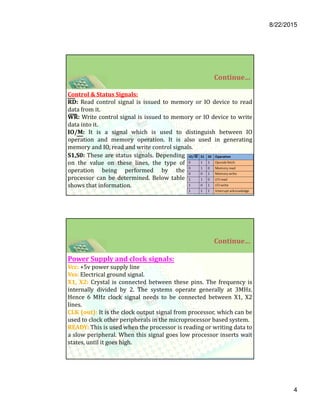
S1,S0: These are status signals. Depending
on the value on these lines, the type of
operation being performed by the
processor can be determined. Below table
shows that information.
Continue…
Power Supply and clock signals:
Vcc: +5v power supply line
Vss: Electrical ground signal.
X1, X2: Crystal is connected between these pins. The frequency is
internally divided by 2. The systems operate generally at 3MHz.
Hence 6 MHz clock signal needs to be connected between X1, X2
lines.
CLK (out): It is the clock output signal from processor, which can be
used to clock other peripherals in the microprocessor based system.
READY: This is used when the processor is reading or writing data to
a slow peripheral. When this signal goes low processor inserts wait
states, until it goes high.
8/22/2015
5
Continue…
Reset Signals:
RESET IN: When low signal is applied on this pin, 8085
resets and the microprocessor boots from 0000h location
in memory i.e. PC is loaded with 0000h location.
RESET OUT: When processor is reset, this signal goes high.
This pin is connected to reset input of other peripherals. So
when processor is reset, other peripherals are also reset.
Serial IO lines:
SID: serial input data, used to receive serial data.
SOD: serial output data, used to send serial data
Continue…
Interrupt Signals:
INTR: interrupt request is general purpose interrupt signal. The interrupting
device needs to send the vector address also.
INTA : is interrupt acknowledging signal. This signal indicates that processor has
accepted the interrupt.
RST7.5, RST6.5, RST5.5: These are external vectored interrupts. When these
interrupt occurs, processor vectors to a specific location.
TRAP: It is a non-mask able interrupt.
DMA signals:
HOLD: This line is used by DMA controller to request microprocessor for system
bus. When this line goes high microprocessor completes its current bus cycle and
issues system bus to DMA controller.
HLDA: HOLD acknowledging signal. Processor acknowledges DMA request using
this signal.
8/22/2015
6
Architecture of 8085 Microprocessor
Fig:- Architecture of 8085 microprocessor
Continue…
The following are the different blocks in the 8085 processor.
ALU:
It is 8-bit ALU. It can perform arithmetic and logical operations on 8-bit
data. If an operation needs to be performed on 16-bit data, it needs to be broken
into two 8-bit parts and each 8-bit operation should be performed on each 8-bit
data. It takes operand inputs from accumulator and a temporary register. Result
of the operation is stored in accumulator. Depending on the result of operation,
flags in flag register values will be changed.
Accumulator
It is a 8-bit register which is used to perform airthmetical and logical
operation. It stores the output of any operation. It also works as registers for i/o
accesses.
Temporary Register
It is a 8-bit register which is used to hold the data on which the
acumulator is computing operation. It is also called as operand register because it
provides operands to ALU.
8/22/2015
7
Continue…
Flag register contains five flags, namely S, Z, CY, AC, P flags.
8085 has two 16- bit register PC and SP. PC always consists of address of next
instruction to be executed. SP always points to top of stack. i.e. address of top
memory location of stack. Stack is a data structure. It is used to store return
addresses whenever call to subprograms or an interrupt occurs.
Two temporary registers W, Z are also present. These are used to hold
temporary results during execution. But these are not accessible to the user.
Incrementer and decrementer address latch is for incrementing the PC content
for every fetch cycle.
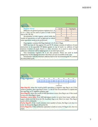
Register Array:
8085 has six general purpose registers B, C, D,
E, H, L. They can be used as pairs to hold 16-bit
data as BC, DE, HL.
Accumulator is 8-bit register which holds the
results of operations as well as operand on which
some operation needs to be performed.
Continue…
Sign flag (S): when the result of ALU operation is negative sign flag is set. If the
result is positive, then sign flag is reset. i. e. the D7 bit of accumulator is copied into
the sign flag, as D7 anyhow contains sign.
Zero flag (Z): when the result of ALU operation is zero, Zero flag is set. If the result
is non-zero then flag is reset.
Auxiliary carry (AC): If an ALU operation results in carry from lower nibble to
upper nibble (or) bit D3 to bit D4, Auxiliary flag is set. Else it is reset. This flag is
used in BCD arithmetic.
Parity flag (P): If the result contains even number of ones, the flag is set else it is
reset. So the parity flag is odd parity bit.
Carry flag (CY): If the arithmetic operation results in carry, CY flag is set, else it is
reset.
Flag register :
8/22/2015
8
Continue…
Instruction Register and Decoding:
Instruction register holds instruction that is fetched from memory. Instruction decoder
decodes the opcode (which is part of fetched instruction present in instruction register).
Instruction register is not accessible to the programmer.
Interrupt Controller:
8085 has 5 external interrupts. TRAP, INTR, RST 5.5, RST 6.5, and RST 7.5. Whenever
processor gets interrupt it finishes current instruction execution and issues INTA (interrupt
acknowledge) signal to the peripheral which raised the interrupt and goes to execute
interrupt service routine. Interrupt controller controls the interrupts.
Serial I/O control:
Serial data can be sent out using SOD pin and serial data can be read from SID pin. It
controls serial IO related operations.
Program Counter
It is a 16 bit register used as memory pointer. It stores the memory address of the next
instruction to be executed. So we can say that this register is used to sequencing the
program. Generally the memory has 16 bit addresses so that it has 16 bit memory. The
program counter is set to 0000H.
Continue…
Stack Pointer
It is also a 16 bit register used as memory pointer. It points to the memory location
called stack. Generally stack is a reserved portion of memory where information
can be stores or taken back together.
Timing and Control Unit
It provides timing and control signal to the microprocessor to perform the various
operation. It has three control signal. It controls all external and internal circuits. It
operates with reference to clock signal. It synchronizes all the data transfers.
There are three control signal:
ALE- Arithmetic Latch Enable, It provides control signal to synchronize the
components of microprocessor.
RD- This is active low used for reading operation.
WR-This is active low used for writing operation.
There are three status signal used in microprocessor S0, S1 and IO/M. It
changes its status according the provided input to these pins.
8/22/2015
9
Thank You
Have a Nice Day

More Related Content

What's hot (14)

PPTX
Introduction to 8085 Microprocessor
Ravi Anand
 
PPT
8085 MICROPROCESSOR
THANDAIAH PRABU
 
PPTX
C programing -Structure
shaibal sharif
 
PPTX
Structures in c language
tanmaymodi4
 
PPTX
Storage class in C Language
Nitesh Kumar Pandey
 
PDF
Assembling and disassembling pc. pdf
JohnRebenRequinto1
 
PPT
binary number system
vishal gupta
 
PDF
POINTERS IN C MRS.SOWMYA JYOTHI.pdf
SowmyaJyothi3
 
PPTX
Programmable peripheral interface 8255
Marajulislam3
 
PPTX
New Microsoft PowerPoint Presentation.pptx
RAJEEVKUMARYADAV11
 
PPTX
Ict 9 module 3, lesson 2.2 system's specification
Yonel Cadapan
 
PDF
Perl Scripting
Varadharajan Mukundan
 
PDF
8259 Programmable Interrupt Controller
abhikalmegh
 
Introduction to 8085 Microprocessor
Ravi Anand
 
8085 MICROPROCESSOR
THANDAIAH PRABU
 
C programing -Structure
shaibal sharif
 
Structures in c language
tanmaymodi4
 
Storage class in C Language
Nitesh Kumar Pandey
 
Assembling and disassembling pc. pdf
JohnRebenRequinto1
 
binary number system
vishal gupta
 
POINTERS IN C MRS.SOWMYA JYOTHI.pdf
SowmyaJyothi3
 
Programmable peripheral interface 8255
Marajulislam3
 
New Microsoft PowerPoint Presentation.pptx
RAJEEVKUMARYADAV11
 
Ict 9 module 3, lesson 2.2 system's specification
Yonel Cadapan
 
Perl Scripting
Varadharajan Mukundan
 
8259 Programmable Interrupt Controller
abhikalmegh
 

Viewers also liked (20)

DOCX
Pin configuration of 8085
82338476
 
PDF
Detailed Explanation of Pin Description of 8085 microprocessor
Ramesh Dabhole
 
PDF
8085 microprocessor Architecture and Pin description
Vijay Kumar
 
DOC
Pin 8085
Ankush Srivastava
 
PDF
8085 microprocessor ramesh gaonkar
SAQUIB AHMAD
 
PPS
Block diagram-of-8085
Dhara Joshi
 
PPTX
8085 full discription
Kartik Kalpande Patil
 
DOCX
8085 microprocessor
ganeshdabhole
 
PDF
Intel 8086 microprocessor
Ravi Yasas
 
PDF
Difference b/w 8085 & 8086
j4jiet
 
PDF
8085 microprocessor notes
Prof. Dr. K. Adisesha
 
PPT
Introduction for microprocessor
THANDAIAH PRABU
 
PPTX
Microprocessor 8085 architecture ppt. april 2013
harshalata
 
PPTX
5.4 Data Bus
lpapadop
 
PPT
Intro To Computer Hardware
iarthur
 
PPTX
Computer system bus
Goran W. Hama Ali
 
PDF
Instruction cycle
Kumar
 
PPT
Chapter 1 Introduction to PC Hardware
askme
 
PDF
8086 microprocessor
Teja Bheemanapally
 
PPT
8085 Architecture & Memory Interfacing1
techbed
 
Pin configuration of 8085
82338476
 
Detailed Explanation of Pin Description of 8085 microprocessor
Ramesh Dabhole
 
8085 microprocessor Architecture and Pin description
Vijay Kumar
 
8085 microprocessor ramesh gaonkar
SAQUIB AHMAD
 
Block diagram-of-8085
Dhara Joshi
 
8085 full discription
Kartik Kalpande Patil
 
8085 microprocessor
ganeshdabhole
 
Intel 8086 microprocessor
Ravi Yasas
 
Difference b/w 8085 & 8086
j4jiet
 
8085 microprocessor notes
Prof. Dr. K. Adisesha
 
Introduction for microprocessor
THANDAIAH PRABU
 
Microprocessor 8085 architecture ppt. april 2013
harshalata
 
5.4 Data Bus
lpapadop
 
Intro To Computer Hardware
iarthur
 
Computer system bus
Goran W. Hama Ali
 
Instruction cycle
Kumar
 
Chapter 1 Introduction to PC Hardware
askme
 
8086 microprocessor
Teja Bheemanapally
 
8085 Architecture & Memory Interfacing1
techbed
 
Ad

Similar to 8085 microprocessor Architecture and pin description (20)

PPTX
8085 architecture
Rishabh Kataria
 
PPTX
8085 architecture
Rishabh Kataria
 
PPTX
8085vs8086 microprocessor and their characteristics and functionalities
emonhassan6464
 
PPTX
unit 2 microprocesor8085 for advantages disadvatage gtu syllabus.pptx
dravidparmar1
 
PPT
8085-microprocessor
ATTO RATHORE
 
PDF
Microprocessors and Controllers Chapter 3 8085 microprocessor.pdf
rodneymandizvidza
 
PPTX
New ideas and General MICROPROCESSOR-PPT.pptx
RavikumarPalani
 
PPTX
Ece 8085-microprocessor-ppt
satyamshra
 
PPTX
Pin Diagram and block diagram 8085 .pptx
YashArya40
 
PPTX
2. 8085-Microprocessor.pptx
ISMT College
 
PDF
Unit 2 8085.pdf
HimanshuPant41
 
PPTX
Architecture and pin diagram of 8085
Suchismita Paul
 
PPTX
8085 microprocessor
Iama Marsian
 
PDF
itft-8085 microprocessor
Shifali Sharma
 
PDF
MPMC UNIT-1. Microprocessor 8085 pdf Microprocessor and Microcontroller
RAHUL RANJAN
 
PDF
Microprocessors and microcontrollers
gomathy S
 
DOC
Microprocessor Basics 8085 Ch-1
Neelam Kapoor
 
PDF
8085_LAB_PROGRAMS.pdf
Koteswari Kasireddy
 
PDF
Lecture1 The 8085 Microprocessor
Zeeshan Ahmed
 
DOCX
c++
Arun Nair
 
8085 architecture
Rishabh Kataria
 
8085 architecture
Rishabh Kataria
 
8085vs8086 microprocessor and their characteristics and functionalities
emonhassan6464
 
unit 2 microprocesor8085 for advantages disadvatage gtu syllabus.pptx
dravidparmar1
 
8085-microprocessor
ATTO RATHORE
 
Microprocessors and Controllers Chapter 3 8085 microprocessor.pdf
rodneymandizvidza
 
New ideas and General MICROPROCESSOR-PPT.pptx
RavikumarPalani
 
Ece 8085-microprocessor-ppt
satyamshra
 
Pin Diagram and block diagram 8085 .pptx
YashArya40
 
2. 8085-Microprocessor.pptx
ISMT College
 
Unit 2 8085.pdf
HimanshuPant41
 
Architecture and pin diagram of 8085
Suchismita Paul
 
8085 microprocessor
Iama Marsian
 
itft-8085 microprocessor
Shifali Sharma
 
MPMC UNIT-1. Microprocessor 8085 pdf Microprocessor and Microcontroller
RAHUL RANJAN
 
Microprocessors and microcontrollers
gomathy S
 
Microprocessor Basics 8085 Ch-1
Neelam Kapoor
 
8085_LAB_PROGRAMS.pdf
Koteswari Kasireddy
 
Lecture1 The 8085 Microprocessor
Zeeshan Ahmed
 
c++
Arun Nair
 
Ad

More from Vijay Kumar (20)

DOCX
Instruction set of 8086
Vijay Kumar
 
PDF
8086 Microprocessor
Vijay Kumar
 
PPTX
Interrupts on 8086 microprocessor by vijay kumar.k
Vijay Kumar
 
DOCX
Assembly Language
Vijay Kumar
 
PDF
8085 instruction set
Vijay Kumar
 
PDF
8085 instruction set and addressing modes
Vijay Kumar
 
PDF
8086 Microprocessor Instruction set
Vijay Kumar
 
PDF
Input output devices
Vijay Kumar
 
PDF
Microprocessors evolution introduction to microprocessor
Vijay Kumar
 
PDF
Memory types
Vijay Kumar
 
PDF
Memory
Vijay Kumar
 
PDF
Evolution of INTEL Microprocessor
Vijay Kumar
 
PPT
Origin of Microprocessor and Classification of Microprocessor
Vijay Kumar
 
PPTX
8085 addressing modes
Vijay Kumar
 
PPTX
Embedded System Real Time Operating System (ERTS) I unit by vijay
Vijay Kumar
 
PPTX
Microcontroller (8051) by K. Vijay Kumar
Vijay Kumar
 
PPTX
8051 microcontroller by K. Vijay Kumar
Vijay Kumar
 
PDF
Rs 232 & usb ieee1394 communication
Vijay Kumar
 
PDF
Embedded real time-systems communication
Vijay Kumar
 
PPTX
8086 Interrupts & With DOS and BIOS by vijay
Vijay Kumar
 
Instruction set of 8086
Vijay Kumar
 
8086 Microprocessor
Vijay Kumar
 
Interrupts on 8086 microprocessor by vijay kumar.k
Vijay Kumar
 
Assembly Language
Vijay Kumar
 
8085 instruction set
Vijay Kumar
 
8085 instruction set and addressing modes
Vijay Kumar
 
8086 Microprocessor Instruction set
Vijay Kumar
 
Input output devices
Vijay Kumar
 
Microprocessors evolution introduction to microprocessor
Vijay Kumar
 
Memory types
Vijay Kumar
 
Memory
Vijay Kumar
 
Evolution of INTEL Microprocessor
Vijay Kumar
 
Origin of Microprocessor and Classification of Microprocessor
Vijay Kumar
 
8085 addressing modes
Vijay Kumar
 
Embedded System Real Time Operating System (ERTS) I unit by vijay
Vijay Kumar
 
Microcontroller (8051) by K. Vijay Kumar
Vijay Kumar
 
8051 microcontroller by K. Vijay Kumar
Vijay Kumar
 
Rs 232 & usb ieee1394 communication
Vijay Kumar
 
Embedded real time-systems communication
Vijay Kumar
 
8086 Interrupts & With DOS and BIOS by vijay
Vijay Kumar
 

Recently uploaded (20)

DOC
MRRS Strength and Durability of Concrete
CivilMythili
 
PDF
6th International Conference on Machine Learning Techniques and Data Science ...
ijistjournal
 
PPTX
site survey architecture student B.arch.
sri02032006
 
PPTX
The Role of Information Technology in Environmental Protectio....pptx
nallamillisriram
 
PPTX
Thermal runway and thermal stability.pptx
godow93766
 
PDF
International Journal of Information Technology Convergence and services (IJI...
ijitcsjournal4
 
PPTX
Pharmaceuticals and fine chemicals.pptxx
jaypa242004
 
DOCX
8th International Conference on Electrical Engineering (ELEN 2025)
elelijjournal653
 
PPTX
Day2 B2 Best.pptx
helenjenefa1
 
PPTX
Hashing Introduction , hash functions and techniques
sailajam21
 
PPT
Oxygen Co2 Transport in the Lungs(Exchange og gases)
SUNDERLINSHIBUD
 
PPTX
REINFORCEMENT AS CONSTRUCTION MATERIALS.pptx
mohaiminulhaquesami
 
PDF
Statistical Data Analysis Using SPSS Software
shrikrishna kesharwani
 
PPTX
Introduction to Design of Machine Elements
PradeepKumarS27
 
PPTX
artificial intelligence applications in Geomatics
NawrasShatnawi1
 
PDF
Unified_Cloud_Comm_Presentation anil singh ppt
anilsingh298751
 
PPTX
Types of Bearing_Specifications_PPT.pptx
PranjulAgrahariAkash
 
PPTX
Arduino Based Gas Leakage Detector Project
CircuitDigest
 
PPTX
Solar Thermal Energy System Seminar.pptx
Gpc Purapuza
 
PDF
monopile foundation seminar topic for civil engineering students
Ahina5
 
MRRS Strength and Durability of Concrete
CivilMythili
 
6th International Conference on Machine Learning Techniques and Data Science ...
ijistjournal
 
site survey architecture student B.arch.
sri02032006
 
The Role of Information Technology in Environmental Protectio....pptx
nallamillisriram
 
Thermal runway and thermal stability.pptx
godow93766
 
International Journal of Information Technology Convergence and services (IJI...
ijitcsjournal4
 
Pharmaceuticals and fine chemicals.pptxx
jaypa242004
 
8th International Conference on Electrical Engineering (ELEN 2025)
elelijjournal653
 
Day2 B2 Best.pptx
helenjenefa1
 
Hashing Introduction , hash functions and techniques
sailajam21
 
Oxygen Co2 Transport in the Lungs(Exchange og gases)
SUNDERLINSHIBUD
 
REINFORCEMENT AS CONSTRUCTION MATERIALS.pptx
mohaiminulhaquesami
 
Statistical Data Analysis Using SPSS Software
shrikrishna kesharwani
 
Introduction to Design of Machine Elements
PradeepKumarS27
 
artificial intelligence applications in Geomatics
NawrasShatnawi1
 
Unified_Cloud_Comm_Presentation anil singh ppt
anilsingh298751
 
Types of Bearing_Specifications_PPT.pptx
PranjulAgrahariAkash
 
Arduino Based Gas Leakage Detector Project
CircuitDigest
 
Solar Thermal Energy System Seminar.pptx
Gpc Purapuza
 
monopile foundation seminar topic for civil engineering students
Ahina5
 

8085 microprocessor Architecture and pin description

  • 1. 8/22/2015 1 Intel 8085 Microprocessor Architecture, Features & Signals Introduction It is invented in 1976. It is an 8-bit microprocessor. It has 16 address lines, therefore it can access 2^16 = 64K bytes of memory. It has 8 Data lines and 16 address lines, out of which 8 address lines are multiplexed with 8 data lines. It provides one Accumulator, one Flag register, 6 General purpose registers(B, C, D, E, H and L) and two special purpose registers (PC, SP). The clock frequency of 8085 microprocessor is 3MHz. 8085 microprocessor provides on chip clock generator, therefore there is no need of external clock generator, but it requires external tuned circuit like LC, RC or crystal. It is available in 40 pin dual in line (DIP) package. It requires a +5volts of power supply.
  • 2. 8/22/2015 2 Continue… It generates 8 bit I/O address, hence it can access 2^8 = 256 input ports and 256 output ports. 8085 has five hardware interrupts: TRAP, RST 5.5, RST 6.5, RST 7.5, and INTR. The hardware interrupt capability of 8085 microprocessor can be increased by providing external hardware. 8085 microprocessor has capability to share its bus with external bus controller (Direct Memory Access controller); for transferring large amount of data from memory to I/O and vice versa. It provides two serial I/O lines which are SOD and SID; it means, serial peripherals can be interfaced with 8085 microprocessor directly. Pin diagram of 8085 Microprocessor
  • 3. 8/22/2015 3 Pin Details of 8085 Microprocessor Address & data lines: Address bus: 8085 has 16-bit address bus AD0-AD7 and A8-A15. In this lower address bus is multiplexed with data bus. A8-A15 lines are unidirectional and AD0-AD7 lines are bidirectional. Data bus: AD7-AD0 is 8-bit bidirectional data bus. It is multiplexed with lower order address bus. ALE: Address latch enable. It is used to de-multiplex AD0-AD7. It is connected to strobe input of latch which is used to separate address and data bus lines. It is issued in first T-state. Address & data lines: Address bus: 8085 has 16-bit address bus AD0-AD7 and A8-A15. In this lower address bus is multiplexed with data bus. A8-A15 lines are unidirectional and AD0-AD7 lines are bidirectional. Data bus: AD7-AD0 is 8-bit bidirectional data bus. It is multiplexed with lower order address bus. ALE: Address latch enable. It is used to de-multiplex AD0-AD7. It is connected to strobe input of latch which is used to separate address and data bus lines. It is issued in first T-state. Continue…
  • 4. 8/22/2015 4 Control & Status Signals: RD: Read control signal is issued to memory or IO device to read data from it. WR: Write control signal is issued to memory or IO device to write data into it. IO/M: It is a signal which is used to distinguish between IO operation and memory operation. It is also used in generating memory and IO, read and write control signals. Continue… S1,S0: These are status signals. Depending on the value on these lines, the type of operation being performed by the processor can be determined. Below table shows that information. Continue… Power Supply and clock signals: Vcc: +5v power supply line Vss: Electrical ground signal. X1, X2: Crystal is connected between these pins. The frequency is internally divided by 2. The systems operate generally at 3MHz. Hence 6 MHz clock signal needs to be connected between X1, X2 lines. CLK (out): It is the clock output signal from processor, which can be used to clock other peripherals in the microprocessor based system. READY: This is used when the processor is reading or writing data to a slow peripheral. When this signal goes low processor inserts wait states, until it goes high.
  • 5. 8/22/2015 5 Continue… Reset Signals: RESET IN: When low signal is applied on this pin, 8085 resets and the microprocessor boots from 0000h location in memory i.e. PC is loaded with 0000h location. RESET OUT: When processor is reset, this signal goes high. This pin is connected to reset input of other peripherals. So when processor is reset, other peripherals are also reset. Serial IO lines: SID: serial input data, used to receive serial data. SOD: serial output data, used to send serial data Continue… Interrupt Signals: INTR: interrupt request is general purpose interrupt signal. The interrupting device needs to send the vector address also. INTA : is interrupt acknowledging signal. This signal indicates that processor has accepted the interrupt. RST7.5, RST6.5, RST5.5: These are external vectored interrupts. When these interrupt occurs, processor vectors to a specific location. TRAP: It is a non-mask able interrupt. DMA signals: HOLD: This line is used by DMA controller to request microprocessor for system bus. When this line goes high microprocessor completes its current bus cycle and issues system bus to DMA controller. HLDA: HOLD acknowledging signal. Processor acknowledges DMA request using this signal.
  • 6. 8/22/2015 6 Architecture of 8085 Microprocessor Fig:- Architecture of 8085 microprocessor Continue… The following are the different blocks in the 8085 processor. ALU: It is 8-bit ALU. It can perform arithmetic and logical operations on 8-bit data. If an operation needs to be performed on 16-bit data, it needs to be broken into two 8-bit parts and each 8-bit operation should be performed on each 8-bit data. It takes operand inputs from accumulator and a temporary register. Result of the operation is stored in accumulator. Depending on the result of operation, flags in flag register values will be changed. Accumulator It is a 8-bit register which is used to perform airthmetical and logical operation. It stores the output of any operation. It also works as registers for i/o accesses. Temporary Register It is a 8-bit register which is used to hold the data on which the acumulator is computing operation. It is also called as operand register because it provides operands to ALU.
  • 7. 8/22/2015 7 Continue… Flag register contains five flags, namely S, Z, CY, AC, P flags. 8085 has two 16- bit register PC and SP. PC always consists of address of next instruction to be executed. SP always points to top of stack. i.e. address of top memory location of stack. Stack is a data structure. It is used to store return addresses whenever call to subprograms or an interrupt occurs. Two temporary registers W, Z are also present. These are used to hold temporary results during execution. But these are not accessible to the user. Incrementer and decrementer address latch is for incrementing the PC content for every fetch cycle. Register Array: 8085 has six general purpose registers B, C, D, E, H, L. They can be used as pairs to hold 16-bit data as BC, DE, HL. Accumulator is 8-bit register which holds the results of operations as well as operand on which some operation needs to be performed. Continue… Sign flag (S): when the result of ALU operation is negative sign flag is set. If the result is positive, then sign flag is reset. i. e. the D7 bit of accumulator is copied into the sign flag, as D7 anyhow contains sign. Zero flag (Z): when the result of ALU operation is zero, Zero flag is set. If the result is non-zero then flag is reset. Auxiliary carry (AC): If an ALU operation results in carry from lower nibble to upper nibble (or) bit D3 to bit D4, Auxiliary flag is set. Else it is reset. This flag is used in BCD arithmetic. Parity flag (P): If the result contains even number of ones, the flag is set else it is reset. So the parity flag is odd parity bit. Carry flag (CY): If the arithmetic operation results in carry, CY flag is set, else it is reset. Flag register :
  • 8. 8/22/2015 8 Continue… Instruction Register and Decoding: Instruction register holds instruction that is fetched from memory. Instruction decoder decodes the opcode (which is part of fetched instruction present in instruction register). Instruction register is not accessible to the programmer. Interrupt Controller: 8085 has 5 external interrupts. TRAP, INTR, RST 5.5, RST 6.5, and RST 7.5. Whenever processor gets interrupt it finishes current instruction execution and issues INTA (interrupt acknowledge) signal to the peripheral which raised the interrupt and goes to execute interrupt service routine. Interrupt controller controls the interrupts. Serial I/O control: Serial data can be sent out using SOD pin and serial data can be read from SID pin. It controls serial IO related operations. Program Counter It is a 16 bit register used as memory pointer. It stores the memory address of the next instruction to be executed. So we can say that this register is used to sequencing the program. Generally the memory has 16 bit addresses so that it has 16 bit memory. The program counter is set to 0000H. Continue… Stack Pointer It is also a 16 bit register used as memory pointer. It points to the memory location called stack. Generally stack is a reserved portion of memory where information can be stores or taken back together. Timing and Control Unit It provides timing and control signal to the microprocessor to perform the various operation. It has three control signal. It controls all external and internal circuits. It operates with reference to clock signal. It synchronizes all the data transfers. There are three control signal: ALE- Arithmetic Latch Enable, It provides control signal to synchronize the components of microprocessor. RD- This is active low used for reading operation. WR-This is active low used for writing operation. There are three status signal used in microprocessor S0, S1 and IO/M. It changes its status according the provided input to these pins.