SlideShare a Scribd company logo
Unit-II
Data link layer
Data link Layer
 Data link layer in simple terms.
 The data link layer in the OSI (Open System
Interconnections) Model, is in between the physical
layer and the network layer. This layer converts the
raw transmission facility provided by the physical
layer to a reliable and error-free link.
 Imagine you want to send a letter to your friend
using regular mail. The data link layer is like the
postal system that ensures your letter gets from your
house to your friend's house reliably.
Data link Layer
 Here's how it works:
 Dividing into Frames:
 Before sending the letter, you break it down into
smaller, manageable pieces called "frames." Each
frame has a part of your message.
 Addressing:
 You put your friend's address on each frame so
that the postal system knows where to deliver
each piece of the letter.
Data link Layer
 Checking for Errors:
 To make sure your friend receives the correct information,
you might include a way for your friend to check if any part
of the letter got damaged during the journey. It's like adding
a quick summary or a code that your friend can use to verify
everything is okay.
 Ordering:
 You number each frame so that your friend can put them in
the right order when they receive the letter. This ensures
that your friend reads the message in the correct sequence.
Data link Layer
 Sending and Receiving:
 The postal system then takes care of sending each frame
individually. Your friend's postal system collects these
frames, checks for errors, puts them in order, and delivers
the complete letter to your friend.
 Acknowledgment:
 Once your friend receives each frame, they might send you
a quick note saying, "I got it!" This way, you know your
letter arrived safely.
Need and Services
 The primary functions and services of the data link layer
include:
 Framing:
 Purpose: The data link layer encapsulates the network layer
packets into frames.
 Service: It adds start and stop markers to define the beginning and
end of a frame, ensuring that the receiver can identify and extract
the data.
 Addressing:
 Purpose: It adds a source and destination address to each frame,
allowing devices on the same network to differentiate between
multiple senders and receivers.
 Service: This enables the delivery of frames to the correct
destination.
Need and Services
 Flow Control:
 Purpose: It manages the flow of data between sender and
receiver to prevent congestion.
 Service: Flow control mechanisms regulate the speed at
which data is sent, preventing the sender from
overwhelming the receiver.
 Error Detection and Correction:
 Purpose: Detect errors that may occur during transmission
and, in some cases, correct them.
 Service: Methods such as CRC (Cyclic Redundancy Check)
are employed to detect errors, and retransmission
mechanisms may be used to correct them.
Need and Services
 Access Control:
 Purpose: It manages access to the physical medium to avoid data
collisions in shared network environments.
 Service: Protocols like CSMA/CD (Carrier Sense Multiple Access with
Collision Detection) or CSMA/CA (Carrier Sense Multiple Access with
Collision Avoidance) help coordinate access to the network channel.
 Link Layer Switching:
 Purpose: In local area networks (LANs), the data link layer is
responsible for forwarding frames between devices within the same
network segment.
 Service: Link layer switches operate at this layer, making decisions
based on MAC addresses to forward frames to the appropriate
destination.
The main functions and the design issues of this
layer are
 Providing services to the network layer
 Framing
 Error Control
 Flow Control
 Services to the Network Layer
 In the OSI Model, each layer uses the services of
the layer below it and provides services to the
layer above it. The data link layer uses the
services offered by the physical layer. The
primary function of this layer is to provide a well
defined service interface to network layer above
it.
 The types of services provided can be of three
types −
 Unacknowledged connectionless service
 Acknowledged connectionless service
 Acknowledged connection - oriented service
Framing:
 Framing in the data link layer involves the process of
creating frames to encapsulate packets of data for
transmission over a network. It's a crucial function
because it helps the receiving device identify the
beginning and end of each set of data.
Framing:
Frame Structure:
 Start and Stop Markers: Frames begin with a start
marker and end with a stop marker. These markers
indicate the start and end of a frame.
 Frame Header: Contains control information, such
as addressing and error-checking details.
 Frame Payload: Carries the actual data being
transmitted.
 Frame Trailer: Often includes error-checking
information, such as a Cyclic Redundancy Check
(CRC), for detecting transmission errors.
Framing:
 Types of Framing
 Fixed-sized Framing
 Here the size of the frame is fixed and so the frame length
acts as delimiter of the frame.
 Example − ATM cells.
 Variable – Sized Framing
 Here, the size of each frame to be transmitted may be
different. So additional mechanisms are kept to mark the
end of one frame and the beginning of the next frame.
 It is used in local area networks.
The four framing methods that are widely used are
 Character count
 Starting and ending characters, with character
stuffing
 Starting and ending flags, with bit stuffing
 Physical layer coding violations
Framing
 Character Count
This method uses a field in the header to specify
the number of characters in the frame. When the
data link layer at the destination sees the character
count, it knows how many characters follow, and
hence where the end of the frame.
Character stuffing
Character stuffing is closely associated with 8-bit
characters and this is a major hurdle in
transmitting arbitrary sized characters.
Framing:
 Byte Stuffing:
 Purpose: Ensures that the start and stop markers within the frame
do not get confused with the actual data.
 How it works: If the data contains a sequence that matches the
frame's start or stop marker, a special byte is inserted to distinguish it
from the actual marker.
 Bit Stuffing:
 Purpose: Prevents long sequences of 0s or 1s in the data from being
misinterpreted as the start or stop markers.
 How it works: Inserts an extra bit after a specific number of
consecutive bits to maintain synchronization between sender and
receiver.
FLOW CONTROL & ERROR CONTROL
Error Control
 The data link layer ensures error free link for data
transmission. The issues with respect to error
control are:
 Dealing with transmission errors
 Sending acknowledgement frames in reliable
connections
 Retransmitting lost frames
 Identifying duplicate frames and deleting them
 Controlling access to shared channels in case of
broadcasting
Flow Control
The data link layer regulates flow control so that a
fast sender does not drown a slow receiver. When
the sender sends frames at very high speeds, a
slow receiver may not be able to handle it. There
will be frame losses even if the transmission is
error-free. The two common approaches for flow
control are −
 Feedback based flow control
 Rate based flow control
PHYSICAL ADDRESSING
 Physical Addressing: The Data Link layer adds a
header to the frame in order to define physical
address of the sender or receiver of the frame, if
the frames are to be distributed to different
systems on the network.
 Physical address is a unique identifier assigned to
a network interface controller (NIC) for use as a
network address in communications within a
network segment. These addresses are primarily
assigned by device manufacturers
Stop and Wait
Stop and Wait
This protocol involves the following transitions:
 A timeout counter is maintained by the sender, which
is started when a frame is sent.
 If the sender receives acknowledgment of the sent
frame within time, the sender is confirmed about
successful delivery of the frame. It then transmits the
next frame in queue.
 If the sender does not receive the acknowledgment
within time, the sender assumes that either the frame
or its acknowledgment is lost in transit. It then
retransmits the frame.
 If the sender receives a negative acknowledgment,
the sender retransmits the frame.
Stop and wait ARQ
Sliding Window
 This protocol improves the efficiency of stop and wait
protocol by allowing multiple frames to be transmitted
before receiving an acknowledgment. The working
principle of this protocol can be described as follows −
 Both the sender and the receiver has finite sized
buffers called windows. The sender and the receiver
agrees upon the number of frames to be sent based
upon the buffer size.
 The sender sends multiple frames in a sequence,
without waiting for acknowledgment. When its sending
window is filled, it waits for acknowledgment. On
receiving acknowledgment, it advances the window
and transmits the next frames, according to the
number of acknowledgments received.
Go-Back-N ARQ
 The working principle of this protocol is:
 The sender has buffers called sending window.
 The sender sends multiple frames based upon the sending-
window size, without receiving the acknowledgment of the
previous ones.
 The receiver receives frames one by one. It keeps track of
incoming frame’s sequence number and sends the
corresponding acknowledgment frames.
 After the sender has sent all the frames in window, it checks up
to what sequence number it has received positive
acknowledgment.
 If the sender has received positive acknowledgment for all the
frames, it sends next set of frames.
 If sender receives NACK or has not receive any ACK for a
particular frame, it retransmits all the frames after which it does
not receive any positive ACK
Go-Back-N ARQ
Go-Back-N ARQ
Go-Back-N ARQ
Go-Back-N ARQ
Go-Back-N ARQ
Go-Back-N ARQ
Go-Back-N ARQ
Selective Repeat ARQ
 In Selective Repeat ARQ, only the erroneous or lost frames are
transmitted, while frames are received and buffered.
 Both the sender and the receiver have buffers called sending
window and receiving window respectively.
 The sender sends multiple frames based upon the sending-
window size, without receiving the acknowledgment of the
previous ones.
 The receiver also receives multiple frames within the
receiving window size.
 The receiver keeps track of incoming frame’s sequence
numbers, buffers the frames in memory.
 It sends ACK for all successfully received frames and sends
NACK for only frames which are missing or damaged.
 The sender in this case, sends only packet for which NACK is
received.
Selective Repeat ARQ
Piggybacking
.
• The discussed protocols are unidirectional, primarily allowing data
frames to move in one direction, although control signals like ACK
and NAK can go both ways. In practice, data frames flow
bidirectionally, requiring a method called piggybacking to enhance
bidirectional protocol efficiency.
• Piggybacking enables a data frame moving from A to B to also convey
control information regarding B's frames and vice versa, streamlining
the communication process. Every node maintains two operational
windows: a send and a receive window, along with a timer overseeing
three events: request, arrival, and time-out.
• This strategy complicates the arrival event, necessitating the
simultaneous handling of control information and the actual data
frame within a singular event, employing both windows at the
respective site. A uniform algorithm, albeit complex, must be
employed by both sites to effectively manage the unified arrival
events.
PIGGYBACKING AND PIPELINING
PIGGYBACKING
HDLC LAN PROTOCOL STACK
 High-level Data Link Control (HDLC) is a group of
communication protocols of the data link layer for
transmitting data between network points or
nodes.
 Since it is a data link protocol, data is organized
into frames.
 A frame is transmitted via the network to the
destination that verifies its successful arrival.
 It is a bit - oriented protocol that is applicable for
both point - to - point and multipoint
communications.
Transfer Modes
HDLC supports two types of transfer modes, normal
response mode and asynchronous balanced mode.
 Normal Response Mode (NRM) Here, two types
−
of stations are there, a primary station that send
commands and secondary station that can respond
to received commands. It is used for both point - to
- point and multipoint communications.
 Asynchronous Balanced Mode (ABM) Here, the
−
configuration is balanced, i.e. each station can both
send commands and respond to commands. It is
used for only point - to - point communications.
HDLC Frame
 HDLC is a bit - oriented protocol where each
frame contains up to six fields. The structure
varies according to the type of frame.
 The fields of a HDLC frame are −
 Flag It is an 8-bit sequence that marks the beginning and
−
the end of the frame. The bit pattern of the flag is 01111110.
 Address It contains the address of the receiver. If the
−
frame is sent by the primary station, it contains the
address(es) of the secondary station(s). If it is sent by the
secondary station, it contains the address of the primary
station. The address field may be from 1 byte to several
bytes.
 Control It is 1 or 2 bytes containing flow and error control
−
information.
 Payload This carries the data from the network layer. Its
−
length may vary from one network to another.
 FCS It is a 2 byte or 4 bytes frame check sequence for error
−
detection. The standard code used is CRC (cyclic redundancy
code)
Types of HDLC Frames
 There are three types of HDLC frames. The type of frame is
determined by the control field of the frame −
 I-frame I-frames or Information frames carry user data
−
from the network layer. They also include flow and error
control information that is piggybacked on user data. The first
bit of control field of I-frame is 0.
 S-frame S-frames or Supervisory frames do not contain
−
information field. They are used for flow and error control
when piggybacking is not required. The first two bits of
control field of S-frame is 10.
 U-frame U-frames or Un-numbered frames are used for
−
myriad miscellaneous functions, like link management. It may
contain an information field, if required. The first two bits of
control field of U-frame is 11
LOGICAL LINK CONTROL AND MEDIA ACCESS
CONTROL SUB-LAYER
The data link layer is the second lowest layer. It is
divided into two sub-layers −
 The logical link control (LLC) sub-layer
 The medium access control (MAC) sub-layer
 Functions of LLC Sub-layer
 The primary function of LLC is to multiplex
protocols over the MAC layer while transmitting
and likewise to de-multiplex the protocols while
receiving.
 LLC provides hop-to-hop flow and error control.
 It allows multipoint communication over
computer network.
 Frame Sequence Numbers are assigned by LLC.
 In case of acknowledged services, it tracks
acknowledgements
 Functions of MAC Layer
 It provides an abstraction of the physical layer to the LLC
and upper layers of the OSI network.
 It is responsible for encapsulating frames so that they are
suitable for transmission via the physical medium.
 It resolves the addressing of source station as well as the
destination station, or groups of destination stations.
 It performs multiple access resolutions when more than
one data frame is to be transmitted. It determines the
channel access methods for transmission.
 It also performs collision resolution and initiating
retransmission in case of collisions.
 It generates the frame check sequences and thus
contributes to protection against transmission errors.
IEEE 802.2 LLC FRAME FORMAT
 In the IEEE 802 reference model of computer networking, the
logical link control (LLC) data communication protocol layer is
the upper sub-layer of the data link layer (layer 2) of the seven-
layer OSI model. The LLC sub-layer provides multiplexing
mechanisms that make it possible for several network protocols
(e.g. IP, IPX, Decnet and Appletalk) to coexist within a multipoint
network and to be transported over the same network medium.
It can also provide flow control and automatic repeat request
(ARQ) error management mechanisms.
 The LLC sub-layer acts as an interface between the media
access control (MAC) sub-layer and the network layer.
 DSAP (Destination Service Access Point) 8 bits
 The Destination Service Access Point (DSAP) identifies the SAP for which the
LPDU is intended. The DSAP consists of six address bits, a user bit (U) and an
Individual/Group (I/G) bit, organized as shown here:
 D-D-D-D-D-D-D- U-I/G
 The U bit indicates whether the address is defined by the IEEE (1) or user-defined
(0). The I/G bit indicates whether the SAP is a group address (1) or individual
address (0). For our purposes, neither of these bits are too important. All you
really need to know is that the DSAP is the destination of the LPDU. Some
common ones appear over and over.

 SSAP (Source Service Access Point) 8 bits.
 The Source Service Access Point (SSAP) identifies the SAP which originated the
LPDU. The SSAP consists of six address bits, a user bit (U) and a
Command/Response (C/R) bit, organized as shown here:
 S-S-S-S-S-S-U-C/R
 The U bit indicates whether the address is defined by the IEEE (1) or user-defined
(0). The C/R bit indicates whether the LPDU is a command or response. When
LPDU frames are received, the C/R bit is not considered part of the SSAP.
Therefore, the SSAP is normally considered to be only the leftmost seven bits.
MAC LAYER PROTOCOLS- STATIC AND DYNAMIC
ALLOCATION
 In the OSI protocol stack, channel allocation is addressed in the
Medium access control (MAC) sub-layer. This is a sub-layer of the
Data Link Layer - considered to be below the Logical Link Control
(LLC) sub-layer. Many LAN technologies, such as Ethernet are based
on this type of architecture. The MAC layer provides an unreliable
connectionless service, if required, the LLC layer can convert this
into a reliable service by using an ARQ protocol.
 Channel allocation done by a set of rules (i.e. a protocol) to allow
each user to communicate and avoid interference and can be
classified as either static or dynamic.
 With a static approach, the channel's capacity is essentially divided
into fixed portions, each user is then allocated a portion for all time.
If the user has no traffic to use in its portion, then it goes unused.
With a dynamic approach the allocation of the channel changes
based on the traffic generated by the users. Generally, a static
allocation performs better when the traffic is predictable. A
dynamic channel allocation tries to get better utilization and lower
PURE AND SLOTTED ALOHA
 Pure Aloha allows the stations to transmit data at any
time whenever they want and after transmitting the
data packet, station waits for some time. If
transmitting station receives an acknowledgement
from the receiving station then it assumes that the
transmission is successful. But if transmitting station
does not receive any acknowledgement within
specified time from the receiving station then it
assumes that the transmission is unsuccessful.
 Transmitting station waits for some random amount
of time. Then after back off time, it transmits the data
packet again and it keeps trying until the back off
limit is reached after which it aborts the transmission.
Slotted Aloha
 Slotted Aloha divides the time of shared channel
into discrete intervals called as time slots. Any
station can transmit its data in any time slot. The
only condition is that station must start its
transmission from the beginning of the time slot.
If the beginning of the slot is missed, then station
has to wait until the beginning of the next time
slot. A collision may occur if two or more stations
try to transmit data at the beginning of the same
time slot.
A computer network is a system of interconnected devices that can share resources and exc
Carrier Sense Multiple Access (CSMA)
Carrier sense multiple access
• To minimize the chance of collision and, therefore, increase the performance,
the CSMA method was developed. The chance of collision can be reduced if a
station senses the medium before trying to use it.
• Carrier sense multiple access (CSMA) requires that each station first listen to
the medium (or check the state of the medium) before sending, so "sense
before transmit" or" listen before talk." CSMA can reduce the possibility of
collision, but it cannot eliminate it.
.
• The possibility of collision still exists because of propagation delay;
when a station sends a frame, it still takes time (although very short)
for the first bit to reach every station and for every station to sense it.
In other words, a station may sense the medium and find it idle, only
because the first bit sent by another station has not yet been received.
.
Vulnerable Time
• The vulnerable time for CSMA is the propagation time Tp. When a
station sends a frame and any other station tries to send a frame
during this time, a collision will result.
• But if the first bit of the frame reaches the end of the medium, every
station will already have heard the bit and will refrain from sending.
.
Persistence Methods
• 1-persistent method
• Non-persistent method
• P-persistent method.
• O-persistent method
.
• 1-Persistent
• The 1-persistent method is simple and straightforward.
In this method, after the station finds the line idle, it
sends its frame immediately (with probability 1). This
method has the highest chance of collision because two
or more stations may find the line idle and send their
frames immediately.
.
Nonpersistent
• In the nonpersistent method, a station that has a frame to send senses
the line. If the line is idle, it sends
immediately. If the line is not idle, it waits a random amount of time
and then senses the line again.
• The nonpersistent approach reduces the chance of collision because it
is unlikely that two or more stations will wait the same amount of
time and retry to send simultaneously. However, this method reduces
the efficiency of the network because the medium remains idle when
there may be stations with frames to send.
.
• P-Persistent
• The p-persistent approach combines the advantages of the other two
strategies. It reduces the chance of
collision and improves efficiency. In this method, after the station finds
the line idle it follows these steps:
• With probability p, the station sends its frame.
• With probability q = 1 - p, the station waits for the beginning of the
next time slot and checks the line again.
• a. If the line is idle, it goes to step 1.
• b. If the line is busy, it acts as though a collision has occurred
and uses the backoff procedure.
.
O-persistent: Each node is assigned a transmission order by a
supervisory node. When the transmission medium goes idle,
nodes wait for their time slot in accordance with their assigned
transmission order. The node assigned to transmit first transmits
immediately. The node assigned to transmit second waits one
time slot (but by that time the first node has already started
transmitting). Nodes monitor the medium for transmissions from
other nodes and update their assigned order with each detected
transmission (i.e. they move one position closer to the front of the
queue). O-persistent CSMA is used by CobraNet, LonWorks and
the controller area network.
IEEE STANDARD 802.3, 802.4, 802.5
 IEEE 802 specifies to a group of IEEE standards. IEEE standards 802 are used
for controlling the Local Area Network and Metropolitan Area Network. The
user layer in IEEE 802 is serviced by the two layers- the data link layer and the
physical layer.
The generally uses specifications of IEEE 802 are:
 IEEE 802.3
 The IEEE 802.3 standard determines the CSMA/CD access control protocol. The
best known scheme for controlling a local area network on a bus structure is
carrier sense multiple action with collision detection(CSMA/CD).
 IEEE 802.4
 IEEE 802.4 describes token bus LAN standards. In token passing methods,
stations connected on a bus are arranged in a logical ring. In this method only
the station having token (token holder)is being permitted to transmit frames.
 IEEE 802.5
 IEEE 802.5 describes the token ring standards. In a token ring a special bit
pattern, called the token, circulates around the ring whenever all stations are
idle. The sequence of token is determined by the physical locations of the
stations on the ring
: Difference among IEEE 802.3, 802.4 and 802.5
Fiber Distributed Data Interface
 FDDI (Fiber Distributed Data Interface) is a set of ANSI and ISO
standards for data transmission on fiber optic lines in a local
area network (LAN) that can extend in range up to 200 km (124
miles). The FDDI protocol is based on the token ring protocol. In
addition to being large geographically, an FDDI local area
network can support thousands of users. FDDI is frequently
used on the backbone for a wide area network (WAN).
 An FDDI network contains two token rings, one for possible
backup in case the primary ring fails. The primary ring offers
up to 100 Mbps capacity. If the secondary ring is not needed for
backup, it can also carry data, extending capacity to 200 Mbps.
The single ring can extend the maximum distance; a dual ring
can extend 100 km (62 miles).
Features of FDDI
 FDDI uses optical fiber as its physical medium.
 It operates in the physical and medium access control (MAC
layer) of the Open Systems Interconnection (OSI) network model.
 It provides high data rate of 100 Mbps and can support
thousands of users.
 It is used in LANs up to 200 kilometers for long distance voice
and multimedia communication.
 It uses ring based token passing mechanism and is derived from
IEEE 802.4 token bus standard.
 It contains two token rings, a primary ring for data and token
transmission and a secondary ring that provides backup if the
primary ring fails.
 FDDI technology can also be used as a backbone for a wide area
network (WAN).
FDDI Frame Format
 The fields of an FDDI frame are −
 Preamble: 1 byte for synchronization.
 Start Delimiter: 1 byte that marks the beginning of the
frame.
 Frame Control: 1 byte that specifies whether this is a
data frame or control frame.
 Destination Address: 2-6 bytes that specifies address of
destination station.
FDDI Frame Format
 Source Address: 2-6 bytes that specifies address
of source station.
 Payload: A variable length field that carries the
data from the network layer.
 Checksum: 4 bytes frame check sequence for
error detection.
 End Delimiter: 1 byte that marks the end of the
frame.

More Related Content

Similar to A computer network is a system of interconnected devices that can share resources and exc (20)

PDF
CN R16 -UNIT-3.pdf
Joshuaeeda1
 
PPTX
Data link layer
Monu Chaudhary
 
PPTX
Computer network coe351- part4- final
Taymoor Nazmy
 
PPT
computer_network_completenotes_unit2.ppt
VasundharaNam1
 
PPTX
DLL services from the computer networks.pptx
ramakrihna
 
PPTX
Data communication network ppt_Unit_4.pptx
BHAVYPATEL34
 
PPT
UNIT-2 Data Link Layer Services, Functions PPT.ppt
cnpnraja
 
PPTX
Unit 3 - Data Link Layer - Part A
Chandan Gupta Bhagat
 
PPTX
Data Link layer in computer netwroks.pptx
RAJASEKARAN G
 
PPTX
Data Communication Unit - II Data Link Layer.pptx
durgakru
 
PPTX
datalinklayermukesh-150130061041-conversion-gate01.pptx
lathass5
 
PDF
CN-unit-ii.its help you for computer network
mansvi202401
 
PPTX
Introduction to data link layer
Shashank HP
 
PPT
Data Link Layer (DLL) is the second layer in the OSI model. It provides error...
nilayarajait
 
PDF
unit2-210710110327.pdf
ssuser3aa461
 
PDF
DLL
Laxma Reddy
 
PPTX
module 2 cn new.pptx
DrPreethiD1
 
PDF
DATA LINK LAYER.pdf
electricalengineerin42
 
PPTX
Unit 2
APARNA P
 
PPTX
Computer networks unit three presentation
manidheergorikapudi
 
CN R16 -UNIT-3.pdf
Joshuaeeda1
 
Data link layer
Monu Chaudhary
 
Computer network coe351- part4- final
Taymoor Nazmy
 
computer_network_completenotes_unit2.ppt
VasundharaNam1
 
DLL services from the computer networks.pptx
ramakrihna
 
Data communication network ppt_Unit_4.pptx
BHAVYPATEL34
 
UNIT-2 Data Link Layer Services, Functions PPT.ppt
cnpnraja
 
Unit 3 - Data Link Layer - Part A
Chandan Gupta Bhagat
 
Data Link layer in computer netwroks.pptx
RAJASEKARAN G
 
Data Communication Unit - II Data Link Layer.pptx
durgakru
 
datalinklayermukesh-150130061041-conversion-gate01.pptx
lathass5
 
CN-unit-ii.its help you for computer network
mansvi202401
 
Introduction to data link layer
Shashank HP
 
Data Link Layer (DLL) is the second layer in the OSI model. It provides error...
nilayarajait
 
unit2-210710110327.pdf
ssuser3aa461
 
module 2 cn new.pptx
DrPreethiD1
 
DATA LINK LAYER.pdf
electricalengineerin42
 
Unit 2
APARNA P
 
Computer networks unit three presentation
manidheergorikapudi
 

Recently uploaded (20)

PPT
Oxygen Co2 Transport in the Lungs(Exchange og gases)
SUNDERLINSHIBUD
 
PDF
UNIT-4-FEEDBACK AMPLIFIERS AND OSCILLATORS (1).pdf
Sridhar191373
 
PDF
PRIZ Academy - Change Flow Thinking Master Change with Confidence.pdf
PRIZ Guru
 
PPTX
Break Statement in Programming with 6 Real Examples
manojpoojary2004
 
PPTX
原版一样(Acadia毕业证书)加拿大阿卡迪亚大学毕业证办理方法
Taqyea
 
PPTX
artificial intelligence applications in Geomatics
NawrasShatnawi1
 
PPTX
Benefits_^0_Challigi😙🏡💐8fenges[1].pptx
akghostmaker
 
PDF
POWER PLANT ENGINEERING (R17A0326).pdf..
haneefachosa123
 
PDF
Statistical Data Analysis Using SPSS Software
shrikrishna kesharwani
 
DOCX
8th International Conference on Electrical Engineering (ELEN 2025)
elelijjournal653
 
PDF
Additional Information in midterm CPE024 (1).pdf
abolisojoy
 
PDF
Zilliz Cloud Demo for performance and scale
Zilliz
 
PDF
MOBILE AND WEB BASED REMOTE BUSINESS MONITORING SYSTEM
ijait
 
PDF
Unified_Cloud_Comm_Presentation anil singh ppt
anilsingh298751
 
PPTX
MobileComputingMANET2023 MobileComputingMANET2023.pptx
masterfake98765
 
PPTX
MPMC_Module-2 xxxxxxxxxxxxxxxxxxxxx.pptx
ShivanshVaidya5
 
PDF
PORTFOLIO Golam Kibria Khan — architect with a passion for thoughtful design...
MasumKhan59
 
PDF
A presentation on the Urban Heat Island Effect
studyfor7hrs
 
PDF
monopile foundation seminar topic for civil engineering students
Ahina5
 
PPTX
Green Building & Energy Conservation ppt
Sagar Sarangi
 
Oxygen Co2 Transport in the Lungs(Exchange og gases)
SUNDERLINSHIBUD
 
UNIT-4-FEEDBACK AMPLIFIERS AND OSCILLATORS (1).pdf
Sridhar191373
 
PRIZ Academy - Change Flow Thinking Master Change with Confidence.pdf
PRIZ Guru
 
Break Statement in Programming with 6 Real Examples
manojpoojary2004
 
原版一样(Acadia毕业证书)加拿大阿卡迪亚大学毕业证办理方法
Taqyea
 
artificial intelligence applications in Geomatics
NawrasShatnawi1
 
Benefits_^0_Challigi😙🏡💐8fenges[1].pptx
akghostmaker
 
POWER PLANT ENGINEERING (R17A0326).pdf..
haneefachosa123
 
Statistical Data Analysis Using SPSS Software
shrikrishna kesharwani
 
8th International Conference on Electrical Engineering (ELEN 2025)
elelijjournal653
 
Additional Information in midterm CPE024 (1).pdf
abolisojoy
 
Zilliz Cloud Demo for performance and scale
Zilliz
 
MOBILE AND WEB BASED REMOTE BUSINESS MONITORING SYSTEM
ijait
 
Unified_Cloud_Comm_Presentation anil singh ppt
anilsingh298751
 
MobileComputingMANET2023 MobileComputingMANET2023.pptx
masterfake98765
 
MPMC_Module-2 xxxxxxxxxxxxxxxxxxxxx.pptx
ShivanshVaidya5
 
PORTFOLIO Golam Kibria Khan — architect with a passion for thoughtful design...
MasumKhan59
 
A presentation on the Urban Heat Island Effect
studyfor7hrs
 
monopile foundation seminar topic for civil engineering students
Ahina5
 
Green Building & Energy Conservation ppt
Sagar Sarangi
 
Ad

A computer network is a system of interconnected devices that can share resources and exc

  • 2. Data link Layer  Data link layer in simple terms.  The data link layer in the OSI (Open System Interconnections) Model, is in between the physical layer and the network layer. This layer converts the raw transmission facility provided by the physical layer to a reliable and error-free link.  Imagine you want to send a letter to your friend using regular mail. The data link layer is like the postal system that ensures your letter gets from your house to your friend's house reliably.
  • 3. Data link Layer  Here's how it works:  Dividing into Frames:  Before sending the letter, you break it down into smaller, manageable pieces called "frames." Each frame has a part of your message.  Addressing:  You put your friend's address on each frame so that the postal system knows where to deliver each piece of the letter.
  • 4. Data link Layer  Checking for Errors:  To make sure your friend receives the correct information, you might include a way for your friend to check if any part of the letter got damaged during the journey. It's like adding a quick summary or a code that your friend can use to verify everything is okay.  Ordering:  You number each frame so that your friend can put them in the right order when they receive the letter. This ensures that your friend reads the message in the correct sequence.
  • 5. Data link Layer  Sending and Receiving:  The postal system then takes care of sending each frame individually. Your friend's postal system collects these frames, checks for errors, puts them in order, and delivers the complete letter to your friend.  Acknowledgment:  Once your friend receives each frame, they might send you a quick note saying, "I got it!" This way, you know your letter arrived safely.
  • 6. Need and Services  The primary functions and services of the data link layer include:  Framing:  Purpose: The data link layer encapsulates the network layer packets into frames.  Service: It adds start and stop markers to define the beginning and end of a frame, ensuring that the receiver can identify and extract the data.  Addressing:  Purpose: It adds a source and destination address to each frame, allowing devices on the same network to differentiate between multiple senders and receivers.  Service: This enables the delivery of frames to the correct destination.
  • 7. Need and Services  Flow Control:  Purpose: It manages the flow of data between sender and receiver to prevent congestion.  Service: Flow control mechanisms regulate the speed at which data is sent, preventing the sender from overwhelming the receiver.  Error Detection and Correction:  Purpose: Detect errors that may occur during transmission and, in some cases, correct them.  Service: Methods such as CRC (Cyclic Redundancy Check) are employed to detect errors, and retransmission mechanisms may be used to correct them.
  • 8. Need and Services  Access Control:  Purpose: It manages access to the physical medium to avoid data collisions in shared network environments.  Service: Protocols like CSMA/CD (Carrier Sense Multiple Access with Collision Detection) or CSMA/CA (Carrier Sense Multiple Access with Collision Avoidance) help coordinate access to the network channel.  Link Layer Switching:  Purpose: In local area networks (LANs), the data link layer is responsible for forwarding frames between devices within the same network segment.  Service: Link layer switches operate at this layer, making decisions based on MAC addresses to forward frames to the appropriate destination.
  • 9. The main functions and the design issues of this layer are  Providing services to the network layer  Framing  Error Control  Flow Control  Services to the Network Layer
  • 10.  In the OSI Model, each layer uses the services of the layer below it and provides services to the layer above it. The data link layer uses the services offered by the physical layer. The primary function of this layer is to provide a well defined service interface to network layer above it.  The types of services provided can be of three types −  Unacknowledged connectionless service  Acknowledged connectionless service  Acknowledged connection - oriented service
  • 11. Framing:  Framing in the data link layer involves the process of creating frames to encapsulate packets of data for transmission over a network. It's a crucial function because it helps the receiving device identify the beginning and end of each set of data.
  • 12. Framing: Frame Structure:  Start and Stop Markers: Frames begin with a start marker and end with a stop marker. These markers indicate the start and end of a frame.  Frame Header: Contains control information, such as addressing and error-checking details.  Frame Payload: Carries the actual data being transmitted.  Frame Trailer: Often includes error-checking information, such as a Cyclic Redundancy Check (CRC), for detecting transmission errors.
  • 13. Framing:  Types of Framing  Fixed-sized Framing  Here the size of the frame is fixed and so the frame length acts as delimiter of the frame.  Example − ATM cells.  Variable – Sized Framing  Here, the size of each frame to be transmitted may be different. So additional mechanisms are kept to mark the end of one frame and the beginning of the next frame.  It is used in local area networks.
  • 14. The four framing methods that are widely used are  Character count  Starting and ending characters, with character stuffing  Starting and ending flags, with bit stuffing  Physical layer coding violations
  • 15. Framing  Character Count This method uses a field in the header to specify the number of characters in the frame. When the data link layer at the destination sees the character count, it knows how many characters follow, and hence where the end of the frame. Character stuffing Character stuffing is closely associated with 8-bit characters and this is a major hurdle in transmitting arbitrary sized characters.
  • 16. Framing:  Byte Stuffing:  Purpose: Ensures that the start and stop markers within the frame do not get confused with the actual data.  How it works: If the data contains a sequence that matches the frame's start or stop marker, a special byte is inserted to distinguish it from the actual marker.  Bit Stuffing:  Purpose: Prevents long sequences of 0s or 1s in the data from being misinterpreted as the start or stop markers.  How it works: Inserts an extra bit after a specific number of consecutive bits to maintain synchronization between sender and receiver.
  • 17. FLOW CONTROL & ERROR CONTROL Error Control  The data link layer ensures error free link for data transmission. The issues with respect to error control are:  Dealing with transmission errors  Sending acknowledgement frames in reliable connections  Retransmitting lost frames  Identifying duplicate frames and deleting them  Controlling access to shared channels in case of broadcasting
  • 18. Flow Control The data link layer regulates flow control so that a fast sender does not drown a slow receiver. When the sender sends frames at very high speeds, a slow receiver may not be able to handle it. There will be frame losses even if the transmission is error-free. The two common approaches for flow control are −  Feedback based flow control  Rate based flow control
  • 19. PHYSICAL ADDRESSING  Physical Addressing: The Data Link layer adds a header to the frame in order to define physical address of the sender or receiver of the frame, if the frames are to be distributed to different systems on the network.  Physical address is a unique identifier assigned to a network interface controller (NIC) for use as a network address in communications within a network segment. These addresses are primarily assigned by device manufacturers
  • 21. Stop and Wait This protocol involves the following transitions:  A timeout counter is maintained by the sender, which is started when a frame is sent.  If the sender receives acknowledgment of the sent frame within time, the sender is confirmed about successful delivery of the frame. It then transmits the next frame in queue.  If the sender does not receive the acknowledgment within time, the sender assumes that either the frame or its acknowledgment is lost in transit. It then retransmits the frame.  If the sender receives a negative acknowledgment, the sender retransmits the frame.
  • 23. Sliding Window  This protocol improves the efficiency of stop and wait protocol by allowing multiple frames to be transmitted before receiving an acknowledgment. The working principle of this protocol can be described as follows −  Both the sender and the receiver has finite sized buffers called windows. The sender and the receiver agrees upon the number of frames to be sent based upon the buffer size.  The sender sends multiple frames in a sequence, without waiting for acknowledgment. When its sending window is filled, it waits for acknowledgment. On receiving acknowledgment, it advances the window and transmits the next frames, according to the number of acknowledgments received.
  • 24. Go-Back-N ARQ  The working principle of this protocol is:  The sender has buffers called sending window.  The sender sends multiple frames based upon the sending- window size, without receiving the acknowledgment of the previous ones.  The receiver receives frames one by one. It keeps track of incoming frame’s sequence number and sends the corresponding acknowledgment frames.  After the sender has sent all the frames in window, it checks up to what sequence number it has received positive acknowledgment.  If the sender has received positive acknowledgment for all the frames, it sends next set of frames.  If sender receives NACK or has not receive any ACK for a particular frame, it retransmits all the frames after which it does not receive any positive ACK
  • 32. Selective Repeat ARQ  In Selective Repeat ARQ, only the erroneous or lost frames are transmitted, while frames are received and buffered.  Both the sender and the receiver have buffers called sending window and receiving window respectively.  The sender sends multiple frames based upon the sending- window size, without receiving the acknowledgment of the previous ones.  The receiver also receives multiple frames within the receiving window size.  The receiver keeps track of incoming frame’s sequence numbers, buffers the frames in memory.  It sends ACK for all successfully received frames and sends NACK for only frames which are missing or damaged.  The sender in this case, sends only packet for which NACK is received.
  • 34. Piggybacking . • The discussed protocols are unidirectional, primarily allowing data frames to move in one direction, although control signals like ACK and NAK can go both ways. In practice, data frames flow bidirectionally, requiring a method called piggybacking to enhance bidirectional protocol efficiency. • Piggybacking enables a data frame moving from A to B to also convey control information regarding B's frames and vice versa, streamlining the communication process. Every node maintains two operational windows: a send and a receive window, along with a timer overseeing three events: request, arrival, and time-out. • This strategy complicates the arrival event, necessitating the simultaneous handling of control information and the actual data frame within a singular event, employing both windows at the respective site. A uniform algorithm, albeit complex, must be employed by both sites to effectively manage the unified arrival events. PIGGYBACKING AND PIPELINING
  • 36. HDLC LAN PROTOCOL STACK  High-level Data Link Control (HDLC) is a group of communication protocols of the data link layer for transmitting data between network points or nodes.  Since it is a data link protocol, data is organized into frames.  A frame is transmitted via the network to the destination that verifies its successful arrival.  It is a bit - oriented protocol that is applicable for both point - to - point and multipoint communications.
  • 37. Transfer Modes HDLC supports two types of transfer modes, normal response mode and asynchronous balanced mode.  Normal Response Mode (NRM) Here, two types − of stations are there, a primary station that send commands and secondary station that can respond to received commands. It is used for both point - to - point and multipoint communications.  Asynchronous Balanced Mode (ABM) Here, the − configuration is balanced, i.e. each station can both send commands and respond to commands. It is used for only point - to - point communications.
  • 38. HDLC Frame  HDLC is a bit - oriented protocol where each frame contains up to six fields. The structure varies according to the type of frame.
  • 39.  The fields of a HDLC frame are −  Flag It is an 8-bit sequence that marks the beginning and − the end of the frame. The bit pattern of the flag is 01111110.  Address It contains the address of the receiver. If the − frame is sent by the primary station, it contains the address(es) of the secondary station(s). If it is sent by the secondary station, it contains the address of the primary station. The address field may be from 1 byte to several bytes.  Control It is 1 or 2 bytes containing flow and error control − information.  Payload This carries the data from the network layer. Its − length may vary from one network to another.  FCS It is a 2 byte or 4 bytes frame check sequence for error − detection. The standard code used is CRC (cyclic redundancy code)
  • 40. Types of HDLC Frames  There are three types of HDLC frames. The type of frame is determined by the control field of the frame −  I-frame I-frames or Information frames carry user data − from the network layer. They also include flow and error control information that is piggybacked on user data. The first bit of control field of I-frame is 0.  S-frame S-frames or Supervisory frames do not contain − information field. They are used for flow and error control when piggybacking is not required. The first two bits of control field of S-frame is 10.  U-frame U-frames or Un-numbered frames are used for − myriad miscellaneous functions, like link management. It may contain an information field, if required. The first two bits of control field of U-frame is 11
  • 41. LOGICAL LINK CONTROL AND MEDIA ACCESS CONTROL SUB-LAYER The data link layer is the second lowest layer. It is divided into two sub-layers −  The logical link control (LLC) sub-layer  The medium access control (MAC) sub-layer
  • 42.  Functions of LLC Sub-layer  The primary function of LLC is to multiplex protocols over the MAC layer while transmitting and likewise to de-multiplex the protocols while receiving.  LLC provides hop-to-hop flow and error control.  It allows multipoint communication over computer network.  Frame Sequence Numbers are assigned by LLC.  In case of acknowledged services, it tracks acknowledgements
  • 43.  Functions of MAC Layer  It provides an abstraction of the physical layer to the LLC and upper layers of the OSI network.  It is responsible for encapsulating frames so that they are suitable for transmission via the physical medium.  It resolves the addressing of source station as well as the destination station, or groups of destination stations.  It performs multiple access resolutions when more than one data frame is to be transmitted. It determines the channel access methods for transmission.  It also performs collision resolution and initiating retransmission in case of collisions.  It generates the frame check sequences and thus contributes to protection against transmission errors.
  • 44. IEEE 802.2 LLC FRAME FORMAT  In the IEEE 802 reference model of computer networking, the logical link control (LLC) data communication protocol layer is the upper sub-layer of the data link layer (layer 2) of the seven- layer OSI model. The LLC sub-layer provides multiplexing mechanisms that make it possible for several network protocols (e.g. IP, IPX, Decnet and Appletalk) to coexist within a multipoint network and to be transported over the same network medium. It can also provide flow control and automatic repeat request (ARQ) error management mechanisms.  The LLC sub-layer acts as an interface between the media access control (MAC) sub-layer and the network layer.
  • 45.  DSAP (Destination Service Access Point) 8 bits  The Destination Service Access Point (DSAP) identifies the SAP for which the LPDU is intended. The DSAP consists of six address bits, a user bit (U) and an Individual/Group (I/G) bit, organized as shown here:  D-D-D-D-D-D-D- U-I/G  The U bit indicates whether the address is defined by the IEEE (1) or user-defined (0). The I/G bit indicates whether the SAP is a group address (1) or individual address (0). For our purposes, neither of these bits are too important. All you really need to know is that the DSAP is the destination of the LPDU. Some common ones appear over and over.   SSAP (Source Service Access Point) 8 bits.  The Source Service Access Point (SSAP) identifies the SAP which originated the LPDU. The SSAP consists of six address bits, a user bit (U) and a Command/Response (C/R) bit, organized as shown here:  S-S-S-S-S-S-U-C/R  The U bit indicates whether the address is defined by the IEEE (1) or user-defined (0). The C/R bit indicates whether the LPDU is a command or response. When LPDU frames are received, the C/R bit is not considered part of the SSAP. Therefore, the SSAP is normally considered to be only the leftmost seven bits.
  • 46. MAC LAYER PROTOCOLS- STATIC AND DYNAMIC ALLOCATION  In the OSI protocol stack, channel allocation is addressed in the Medium access control (MAC) sub-layer. This is a sub-layer of the Data Link Layer - considered to be below the Logical Link Control (LLC) sub-layer. Many LAN technologies, such as Ethernet are based on this type of architecture. The MAC layer provides an unreliable connectionless service, if required, the LLC layer can convert this into a reliable service by using an ARQ protocol.  Channel allocation done by a set of rules (i.e. a protocol) to allow each user to communicate and avoid interference and can be classified as either static or dynamic.  With a static approach, the channel's capacity is essentially divided into fixed portions, each user is then allocated a portion for all time. If the user has no traffic to use in its portion, then it goes unused. With a dynamic approach the allocation of the channel changes based on the traffic generated by the users. Generally, a static allocation performs better when the traffic is predictable. A dynamic channel allocation tries to get better utilization and lower
  • 47. PURE AND SLOTTED ALOHA  Pure Aloha allows the stations to transmit data at any time whenever they want and after transmitting the data packet, station waits for some time. If transmitting station receives an acknowledgement from the receiving station then it assumes that the transmission is successful. But if transmitting station does not receive any acknowledgement within specified time from the receiving station then it assumes that the transmission is unsuccessful.  Transmitting station waits for some random amount of time. Then after back off time, it transmits the data packet again and it keeps trying until the back off limit is reached after which it aborts the transmission.
  • 48. Slotted Aloha  Slotted Aloha divides the time of shared channel into discrete intervals called as time slots. Any station can transmit its data in any time slot. The only condition is that station must start its transmission from the beginning of the time slot. If the beginning of the slot is missed, then station has to wait until the beginning of the next time slot. A collision may occur if two or more stations try to transmit data at the beginning of the same time slot.
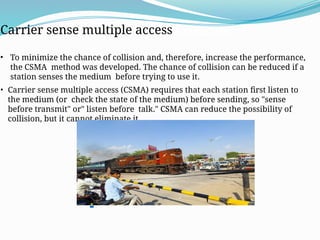
  • 50. Carrier Sense Multiple Access (CSMA) Carrier sense multiple access • To minimize the chance of collision and, therefore, increase the performance, the CSMA method was developed. The chance of collision can be reduced if a station senses the medium before trying to use it. • Carrier sense multiple access (CSMA) requires that each station first listen to the medium (or check the state of the medium) before sending, so "sense before transmit" or" listen before talk." CSMA can reduce the possibility of collision, but it cannot eliminate it. .
  • 51. • The possibility of collision still exists because of propagation delay; when a station sends a frame, it still takes time (although very short) for the first bit to reach every station and for every station to sense it. In other words, a station may sense the medium and find it idle, only because the first bit sent by another station has not yet been received. .
  • 52. Vulnerable Time • The vulnerable time for CSMA is the propagation time Tp. When a station sends a frame and any other station tries to send a frame during this time, a collision will result. • But if the first bit of the frame reaches the end of the medium, every station will already have heard the bit and will refrain from sending. .
  • 53. Persistence Methods • 1-persistent method • Non-persistent method • P-persistent method. • O-persistent method .
  • 54. • 1-Persistent • The 1-persistent method is simple and straightforward. In this method, after the station finds the line idle, it sends its frame immediately (with probability 1). This method has the highest chance of collision because two or more stations may find the line idle and send their frames immediately. .
  • 55. Nonpersistent • In the nonpersistent method, a station that has a frame to send senses the line. If the line is idle, it sends immediately. If the line is not idle, it waits a random amount of time and then senses the line again. • The nonpersistent approach reduces the chance of collision because it is unlikely that two or more stations will wait the same amount of time and retry to send simultaneously. However, this method reduces the efficiency of the network because the medium remains idle when there may be stations with frames to send. .
  • 56. • P-Persistent • The p-persistent approach combines the advantages of the other two strategies. It reduces the chance of collision and improves efficiency. In this method, after the station finds the line idle it follows these steps: • With probability p, the station sends its frame. • With probability q = 1 - p, the station waits for the beginning of the next time slot and checks the line again. • a. If the line is idle, it goes to step 1. • b. If the line is busy, it acts as though a collision has occurred and uses the backoff procedure. .
  • 57. O-persistent: Each node is assigned a transmission order by a supervisory node. When the transmission medium goes idle, nodes wait for their time slot in accordance with their assigned transmission order. The node assigned to transmit first transmits immediately. The node assigned to transmit second waits one time slot (but by that time the first node has already started transmitting). Nodes monitor the medium for transmissions from other nodes and update their assigned order with each detected transmission (i.e. they move one position closer to the front of the queue). O-persistent CSMA is used by CobraNet, LonWorks and the controller area network.
  • 58. IEEE STANDARD 802.3, 802.4, 802.5  IEEE 802 specifies to a group of IEEE standards. IEEE standards 802 are used for controlling the Local Area Network and Metropolitan Area Network. The user layer in IEEE 802 is serviced by the two layers- the data link layer and the physical layer. The generally uses specifications of IEEE 802 are:  IEEE 802.3  The IEEE 802.3 standard determines the CSMA/CD access control protocol. The best known scheme for controlling a local area network on a bus structure is carrier sense multiple action with collision detection(CSMA/CD).  IEEE 802.4  IEEE 802.4 describes token bus LAN standards. In token passing methods, stations connected on a bus are arranged in a logical ring. In this method only the station having token (token holder)is being permitted to transmit frames.  IEEE 802.5  IEEE 802.5 describes the token ring standards. In a token ring a special bit pattern, called the token, circulates around the ring whenever all stations are idle. The sequence of token is determined by the physical locations of the stations on the ring
  • 59. : Difference among IEEE 802.3, 802.4 and 802.5
  • 60. Fiber Distributed Data Interface  FDDI (Fiber Distributed Data Interface) is a set of ANSI and ISO standards for data transmission on fiber optic lines in a local area network (LAN) that can extend in range up to 200 km (124 miles). The FDDI protocol is based on the token ring protocol. In addition to being large geographically, an FDDI local area network can support thousands of users. FDDI is frequently used on the backbone for a wide area network (WAN).  An FDDI network contains two token rings, one for possible backup in case the primary ring fails. The primary ring offers up to 100 Mbps capacity. If the secondary ring is not needed for backup, it can also carry data, extending capacity to 200 Mbps. The single ring can extend the maximum distance; a dual ring can extend 100 km (62 miles).
  • 61. Features of FDDI  FDDI uses optical fiber as its physical medium.  It operates in the physical and medium access control (MAC layer) of the Open Systems Interconnection (OSI) network model.  It provides high data rate of 100 Mbps and can support thousands of users.  It is used in LANs up to 200 kilometers for long distance voice and multimedia communication.  It uses ring based token passing mechanism and is derived from IEEE 802.4 token bus standard.  It contains two token rings, a primary ring for data and token transmission and a secondary ring that provides backup if the primary ring fails.  FDDI technology can also be used as a backbone for a wide area network (WAN).
  • 62. FDDI Frame Format  The fields of an FDDI frame are −  Preamble: 1 byte for synchronization.  Start Delimiter: 1 byte that marks the beginning of the frame.  Frame Control: 1 byte that specifies whether this is a data frame or control frame.  Destination Address: 2-6 bytes that specifies address of destination station. FDDI Frame Format
  • 63.  Source Address: 2-6 bytes that specifies address of source station.  Payload: A variable length field that carries the data from the network layer.  Checksum: 4 bytes frame check sequence for error detection.  End Delimiter: 1 byte that marks the end of the frame.