![International Journal of Power Electronics and Drive System (IJPEDS)
Vol. 5, No. 2, October 2014, pp. 176~184
ISSN: 2088-8694 176
Journal homepage: http://iaesjournal.com/online/index.php/IJPEDS
A Performance Comparison of DFIG using Power Transfer
Matrix and Direct Power Control Techniques
K. Viswanadha S Murthy, M. Kirankumar, G.R.K. Murthy
Department of Electrical and Electronics Engineering, KL University, Andhra Pradesh, India
Article Info ABSTRACT
Article history:
Received Mar 13, 2014
Revised Jun 5, 2014
Accepted Jul 2, 2014
This paper presents a direct power control and power transfer matrix model
for a doubly-fed induction generator (DFIG) wind energy system (WES).
Control of DFIG wind turbine system is traditionally based on either stator-
flux-oriented or stator-voltage-oriented vector control. The performance of
Direct Power Control (DPC) and Power transfer Matrix control for the same
wind speed are studied. The Power transfer matrix Control gave better
results. The validity and performance of the proposed modelling and control
approaches are investigated using a study system consisting of a grid
connected DFIG WES. The performance of DFIG with Power Transfer
Matrix and Direct Power Control (DPC) techniques are obtained through
simulation. The time domain simulation of the study system using MATLAB
Simulink is carried out. The results obtained in the two cases are compared.
Keyword:
Doubly-fedInduction generator
(DFIG)
Direct Power control (DPC)
Power Transfer Matrix
Pulse width modulation (PWM)
Wind energy
Copyright © 2014 Institute of Advanced Engineering and Science.
All rights reserved.
Corresponding Author:
G.R.K. Murthy,
Departement of Electrical and Electronics Engineering
KL University
Greenfields, Vaddeswaram, Guntur District, Andhra Pradesh 522502, India
Email: drgrkmurthy@kluniversity.in
1. INTRODUCTION
Generation of electricity has been largely dominated by nuclear, hydro and fossil-fueled thermal
plants. Generally this type of generation is considered as conventional power generation. The main drawback
of most conventional power plants is the adverse impact on the environment. The gradual depletion of fossil-
fuel (such as coal, gas) reserves is also a concern. The solution to these problems lies in adopting non-
conventional methods such as wind, solar etc. in power generation. Wind is regarded as the best suitable
renewable energy resource for production of power and the best alternative to the conventional energy
resources mainly because of availability of large wind turbines [1].
For the last two decades, research is being carried out specifically on Wind Energy Systems to
capture more power at fluctuating wind speeds. With the improvement in the power electronic technology
constant speed constant frequency (CSCF) generators were replaced by variable speed constant frequency
(VSCF) generators in WES. The Doubly Fed Induction Generator (DFIG) is currently the choice of generator
for multi-MW wind turbines .The aerodynamic system must be capable of operating over a wide wind speed
range in order to achieve optimum aerodynamic efficiency by tracking the optimum tip-speed
ratio.Therefore, the generator’s rotor must be able to operate at a variable rotational speed. TheDFIG system,
therefore operates in both sub- synchronous and super-synchronous modes with a rotorspeed range around
the synchronous speed. The stator circuit is directly connected to thegrid while the rotor winding is connected
via slip-rings to a three-phase converter. Forvariable - speed systems where the speed range requirements are
small, (for example ±30% ofsynchronous speed) the DFIG offers adequate performance and is sufficient for
the speedrange required to exploit typical wind resources.
The doubly fed induction generator (DFIG) based wind turbine with variable speed and variable
pitch control scheme is the most popular wind power generation system in the wind power industry. This](https://image.slidesharecdn.com/055jun146150-12866-1-ededit-171213060823/85/A-Performance-Comparison-of-DFIG-using-Power-Transfer-Matrix-and-Direct-Power-Control-Techniques-1-320.jpg)
![IJPEDS ISSN: 2088-8694
A Performance Comparison of DFIG using Power Transfer Matrix and Direct… (K.Viswanadha S Murthy)
177
machine can be operated either in grid connected mode or in standalone mode. This system has recently
become very popular as generator for variable speed wind turbines. The major advantage of the doubly fed
induction generator (DFIG), which has made it popular, is that the power electronic equipment has to handle
only a fraction (20-30%) of the total system power [2], [3]. That means the losses in the power electronic
equipment can be reduced in comparison to power electronic equipment that has to handle the total system
power as for a direct-driven synchronous generator, apart from the cost saving of using smaller converters.
Control of the DFIG is more complicated than the control of a standard induction machine. In order to
control the DFIG rotor current is controlled by a power electronic converter. One common way of controlling
the rotor current is by means of Field oriented (vector) control. Direct torque control (DTC) of induction
machines, provides an alternative to vector control [5]. Based on the principles of DTC strategy, direct power
control (DPC) was developed for three-phase pulse width modulation (PWM) converters.
Power transfer matrix is a control technique of DFIG which uses instantaneous real and reactive
power instead of dq components of currents in a vector control scheme. The main features of the proposed
model compared to conventional models in the dq frame of reference are [6].
a) Robustness: The waveforms of power components are independent of a reference frame;
therefore, this approach is inherently robust against unaccounted dynamics such as PLL.
b) Simplicity of realization: The power components (state variables of a feedback control loop) can
be directly obtained from phase voltage/current quantities, which simplify the Implementation of the control
system.
Figure 1. Structure of DFIG wind power generating system
2. WIND TURBINE MODEL
The wind turbine characteristics must be analyzed for getting optimum power curve (Popt). The
power output of Wind turbine is given by [4]:
P0= Cp*PV = 0.5 Sw V3
Cp (1)
Where ‘’is the air density; Sw is wind turbine blade swept area in the wind, V is wind speed. Cp represents
the power conversion efficiency of the wind turbine. It is a function of (Tip-speed Ratio).
=
ᴨ
=
Where ‘R’ is the blade radius; is the angular velocity of the rotating blades; N is the rotational speed in
revolutions per second, and V∞ is thewind speed without the interruption of rotor. Cp can be calculated by
using the formula:
Cp=0.5716* (116*- 0.4 21 λ
1 1
0.08
0.035
1
Maximum power from the wind turbine is:
Pmax=K
](https://image.slidesharecdn.com/055jun146150-12866-1-ededit-171213060823/85/A-Performance-Comparison-of-DFIG-using-Power-Transfer-Matrix-and-Direct-Power-Control-Techniques-2-320.jpg)
![ ISSN: 2088-8694
IJPEDS Vol. 5, No. 2, October 2014 : 176 – 184
178
Where 0.5Sw *Cp
3. DIRECT POWER CONTROL OF DFIG
Figure 2. Equivalent circuit of DFIG in the
synchronous d-q reference frame
Figure 3. Stator and rotor flux vectors in
synchronous d-q frame
The equivalent circuit of a DFIG in the synchronous d–qframe, rotating at the speed of ω1, is shown
in Figure 2. The d-axisof the synchronous frame is fixed to the stator flux, as shown in Figure 3. With
reference to Figure 2, the stator voltage vector in the synchronousd–q reference frame is given as:
Vs
s
= Rs Is
s
+ (dΨs
s
/dt) + jΨs
s
(5)
Under balanced ac voltage supply, the amplitude and rotating speed of the stator flux are constant.
Therefore, in the synchronous d–q frame, the stator flux maintains a constant value [5]. Thus;
Ψs
s
= Ψsd
(dΨs
s
/dt) = 0 (6)
Considering Equation (5) and neglecting the voltage drop across the statorresistance, Equation (6)
can be simplified as:
Vs
s
= jΨs
s
= jΨsd (7)
The stator current in the synchronous d-q frame is given as:
rs
s
rm
s
s
s
mrs
s
rm
s
srs
s
LL
L
LLLL
LL
I
2
(8)
Thus the stator active and reactive power inputs can be calculated as:
rd
m
sdr
sdrqsdss
rs
rqrdm
s
sd
sds
rs
s
rm
s
s
s
sdss
L
L
jkjQP
LL
jL
LjjQP
LL
L
LjjQP
1
1
1
2/3
2/3
(9)
Splitting Equation (9) into real and imaginary parts yields:
sd
m
r
rdsds
rqsds
L
L
kQ
kP
1
1
(10)](https://image.slidesharecdn.com/055jun146150-12866-1-ededit-171213060823/85/A-Performance-Comparison-of-DFIG-using-Power-Transfer-Matrix-and-Direct-Power-Control-Techniques-3-320.jpg)
![IJPEDS ISSN: 2088-8694
A Performance Comparison of DFIG using Power Transfer Matrix and Direct… (K.Viswanadha S Murthy)
179
As the stator flux is constant, according to Equation (10), the active and reactive power changes
over a constant period are given by :
rdsds
rqsds
KQ
KP
1
1
(11)
Equation (10) indicates that the stator reactive and active power changes are determined by the changes of
the rotor flux components on the d-q axis, i.e. , ∆Ψrd and ,∆Ψrq, respectively.
4. ACTIVE AND REACTIVE POWER CONTROL
The active and reactive power control calculates the required rotor voltage that will reduce the
active and reactive power errors to zero during a constant sampling time period of Ts. A PWM modulator is
then used to generate the applied rotor voltage for the time period of Ts.
Within the time period of Ts, the rotor voltage required to eliminate the power errors in d-q
reference frame are calculated as [7]-[9]:
rds
sd
s
s
rq
rqs
sd
s
s
rd
k
P
T
V
k
Q
T
V
1
1
1
1
(12)
However, its accuracy could be affected by the variation of Lm (Mutual inductance). An alternative method
based on Equation (11) gives:
sd
s
rq
sd
m
r
sd
s
rd
k
P
L
L
k
Q
1
1
(13)
From the Equation (12) and (13) we get:
sd
m
r
sd
s
s
sd
s
s
sd
s
s
sd
s
s
L
L
k
Q
k
P
T
k
P
k
Q
T
11
rq
11
rd
1
V
1
V
(14)
The first terms on the right hand side reduce power errors while the second terms compensate the
rotor slip that causes the different rotating speeds of the stator and rotor flux.
Figure 4. Schematic diagram of the DPC for a DFIG system](https://image.slidesharecdn.com/055jun146150-12866-1-ededit-171213060823/85/A-Performance-Comparison-of-DFIG-using-Power-Transfer-Matrix-and-Direct-Power-Control-Techniques-4-320.jpg)
![ ISSN: 2088-8694
IJPEDS Vol. 5, No. 2, October 2014 : 176 – 184
180
5. PRINCIPLES OF POWER TRANSFERMATRIX
The schematic diagram of a DFIG wind turbine generator is represented in Figure 1. The power
Converter includes Rotor-side-converter (RSC) to control speed of the generator and Grid-side converter
(GSC) to inject reactive power to the system. The instantaneous real and reactive power components of the
grid side converter, pg(t)and qg(t)in the synchronous d-q frame of reference are [6]:
gq
gd
sdsq
sqsd
g
g
i
i
vv
vv
tq
tp
2
3
)(
)(
(15)
6. MODEL OF DFIG USING INSTANTANEOUS POWER COMPONENTS
The change in real power and reactive power can be expressed as [12]-[14]:
rdsdsqsssl
s
rdsqsdssls
s
uggqgp
dt
dq
uggqpg
dt
dp
541
541
(16)
Where,
rs
sdm
rs
ssrs
rqrdrq
s
s
rqrdrd
LL
vL
g
LL
rLLr
g
vgvgu
L
v
vgvgu
'2'1
23
'
2
32
2
3
;
2
3
rs
sqrrsdr
rs
sqrrsdr
rs
sqm
LL
vLvr
g
LL
vLvr
g
LL
vL
g
'5
'4
'3
2
3
2
3
2
3
(17)
The electromechanical dynamic model of the machine is:
me
r
TT
J
P
dt
d
(18)
Where P,J and Tm are the number of pole pairs, inertia of therotor, and mechanical torque of the machine,
respectively. Theelectric torque is given by [10], [11]:
sdsqsqsde iiPT
2
3 (19)
mss
r
T
J
P
qgpg
dt
d
76
(20)
Where,
2
2
7
2
2
6
s
sqsqsdsd
s
sqsdsdsq
v
vv
J
P
g
v
vv
J
P
g
(21)](https://image.slidesharecdn.com/055jun146150-12866-1-ededit-171213060823/85/A-Performance-Comparison-of-DFIG-using-Power-Transfer-Matrix-and-Direct-Power-Control-Techniques-5-320.jpg)

![IJPEDS ISSN: 2088-8694
A Performance Comparison of DFIG using Power Transfer Matrix and Direct… (K.Viswanadha S Murthy)
183
Figure 10(b). Vdc from DPC
The results are obtained at a wind speed of 12 m/sec. The trapezoidal wave form shown in Figure 7
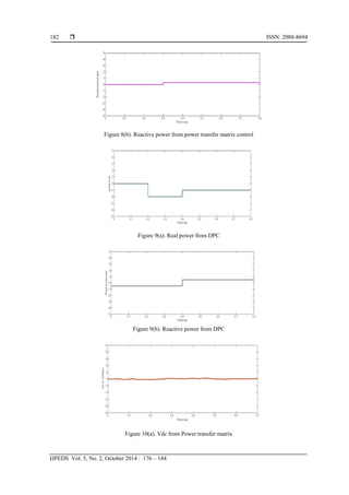
shows the pattern of step change in the reactive reference which is applied to both the control techniques.The
trapezoidal pattern wasselected to examine the system behavior following variation inthe wind speed with
both negative and positive slopes. The selectedwind speed pattern spans an input mechanical wind
powerfrom 0.7 to 1 p.u. (70 to 100% of the turbine-generator ratedpower).
Figures 8(a) and 8(b) show the Real and Reactive power tracking of DFIG against disturbances
present in the given wind speed pattern. Because of coupling of all powers interlinked to each other, the
coupling effect is obtained at t=0.3 sec.
Figure 9(a) shows the Real power tracking of DFIG against disturbances in the given wind speed
pattern. Here the dip in the wave form shows the start of real power generation at t=0.2 sec. Figure 9(b)
indicates the reactive power absorption for 0.4 sec.
Figures 10(a) and 10(b) show the dc link voltages of Power transfer matrix control and DPC.The
change in wind speed leads to the fluctuations of the dc link voltage. Due to the coupling of all powers vdc of
power transfer matrix have some variations. Where as in DPC there is no coupling of the powers and the dc
link voltage is constant. Change in wind speed does not affect dc link voltage
7. CONCLUSION
Upon examining the results of both Power transfer matrix and DPC techniques for the same
disturbances the Real power generation is better in power transfer matrix control than with DPC. Also the
generation of power starts in DPC with a delay of 0.2 sec. Hence power transfer matrix method is giving
better results than the DPC method.
REFERENCES
[1] Wind technology 2011024/29. Global wind energy council (online). Available at www.gwec.net
[2] LH Hansen, L Helle, F Balaabjerg, E Ritchie, S munk-nielsen, H binder. Conseptual Survey of Generators And
Power Electronics For Wind Turbines. Riso national laboratory.
[3] L Morel, H Godfroid. Dfim Converter Optimisation And Field Oriented Control Without Positioning Sensor. IEE
proc.elctr.powerappl. 1998; 145(4): 360-368.
[4] SN Bhadra, D Kastha, S Banarjee. Wind Electrical Systems. Oxford University press
[5] Dawei Zhi, Lie Xu. Direct Power Control of DFIG with Constant Swtching Frequency and Improved Transient
Performance”IEEE Transactions on Energy Conversion. 2007; 22(1).
[6] Esmaeil Rezaei, Ahmadreza Tabesh, Mohammad Ebrahimi. Dynamic Model and Control of DFIG Wind Energy
Systems Based on Power Transfer Matrix. IEEE Transactions on Power Delivery. 2012; 27(3).
[7] P Krause, O Wasynczuk, S Sudhoff, IPE Society. Analysis of Electric Machinery and Drive Systems. Piscataway,
NJ: IEEE. 2002.
[8] Abdelmalek Boulahia. Mentouri university of Constantine, Algeria; Khalil NABTI; Hocine BENALLA, Algeria
Direct Power Control for Threelevel NPC Based PWM AC/DC/AC Converter in Doubly Fed Induction Generators
Based Wind Turbine International Journal of Electrical and Computer Engineering (IJECE). 2012; 2(3): 425-436.
[9] NRN Idris, AHM Yatim.Direct Torque Control of Induction Machines with Constant Switching Frequency and
Reduced Torque Ripple. IEEE Trans. Ind. Electron., 2004; 51(4): 758–767.
[10] J Kang, S Sul. New Direct Torque Control of Induction Motor for Minimum Torque Ripple and Constant Switching
Frequency. IEEE Trans. Ind. Appl., 1999; 35(5): 1076–1082.](https://image.slidesharecdn.com/055jun146150-12866-1-ededit-171213060823/85/A-Performance-Comparison-of-DFIG-using-Power-Transfer-Matrix-and-Direct-Power-Control-Techniques-8-320.jpg)
![ ISSN: 2088-8694
IJPEDS Vol. 5, No. 2, October 2014 : 176 – 184
184
[11] T Noguchi, H Tomiki, S Kondo, I Takahashi. Direct Power Control Of Pwm Converter Without Power-Source
Voltage Sensors. IEEE Trans.Ind. Appl., 1998; 34(3): 473–479.
[12] G Escobar, AM Stankovic, JM Carrasco, E Galvan, R Ortega. Analysis and Design Of Direct Power Control (Dpc)
For A Three Phase Synchronousrectifier Via Output Regulation Subspaces. IEEE Trans. Power Electron., 2003;
18(3): 823–830.
[13] M Malinowski, MP Kazmierkowski, S Hansen, F Blaabjerg, GD Marques. VIRTUAL-FLUX-BASED DIRECT
POWER CONTROL OF THREE-PHASEPWM RECTIFIERS. IEEE Trans. Ind. Appl., 2001; 37(4): 1019–1027.
[14] KP Gokhale, DW Karraker, SJ Heikkila. Controller for A Woundrotor Slip Ring Induction Machine. U.S. Patent 6
448 735 B1. 2002.
[15] L Xu, P Cartwright. Direct active and reactive power control of DFIGfor wind energy generation. IEEE Trans.
Energy Convers., 2006; 21(3): 750–758.
[16] Wang Zezhong, Liu Qihui. Analysis of DFIG Wind Turbine during Steadystate and Transient Operation.
TELKOMNIKA Indonesian Journal of Electrical Engineering. 2014; 12(6): 4148-4156.](https://image.slidesharecdn.com/055jun146150-12866-1-ededit-171213060823/85/A-Performance-Comparison-of-DFIG-using-Power-Transfer-Matrix-and-Direct-Power-Control-Techniques-9-320.jpg)
A Performance Comparison of DFIG using Power Transfer Matrix and Direct Power Control Techniques
- 1. International Journal of Power Electronics and Drive System (IJPEDS) Vol. 5, No. 2, October 2014, pp. 176~184 ISSN: 2088-8694 176 Journal homepage: http://iaesjournal.com/online/index.php/IJPEDS A Performance Comparison of DFIG using Power Transfer Matrix and Direct Power Control Techniques K. Viswanadha S Murthy, M. Kirankumar, G.R.K. Murthy Department of Electrical and Electronics Engineering, KL University, Andhra Pradesh, India Article Info ABSTRACT Article history: Received Mar 13, 2014 Revised Jun 5, 2014 Accepted Jul 2, 2014 This paper presents a direct power control and power transfer matrix model for a doubly-fed induction generator (DFIG) wind energy system (WES). Control of DFIG wind turbine system is traditionally based on either stator- flux-oriented or stator-voltage-oriented vector control. The performance of Direct Power Control (DPC) and Power transfer Matrix control for the same wind speed are studied. The Power transfer matrix Control gave better results. The validity and performance of the proposed modelling and control approaches are investigated using a study system consisting of a grid connected DFIG WES. The performance of DFIG with Power Transfer Matrix and Direct Power Control (DPC) techniques are obtained through simulation. The time domain simulation of the study system using MATLAB Simulink is carried out. The results obtained in the two cases are compared. Keyword: Doubly-fedInduction generator (DFIG) Direct Power control (DPC) Power Transfer Matrix Pulse width modulation (PWM) Wind energy Copyright © 2014 Institute of Advanced Engineering and Science. All rights reserved. Corresponding Author: G.R.K. Murthy, Departement of Electrical and Electronics Engineering KL University Greenfields, Vaddeswaram, Guntur District, Andhra Pradesh 522502, India Email: [email protected] 1. INTRODUCTION Generation of electricity has been largely dominated by nuclear, hydro and fossil-fueled thermal plants. Generally this type of generation is considered as conventional power generation. The main drawback of most conventional power plants is the adverse impact on the environment. The gradual depletion of fossil- fuel (such as coal, gas) reserves is also a concern. The solution to these problems lies in adopting non- conventional methods such as wind, solar etc. in power generation. Wind is regarded as the best suitable renewable energy resource for production of power and the best alternative to the conventional energy resources mainly because of availability of large wind turbines [1]. For the last two decades, research is being carried out specifically on Wind Energy Systems to capture more power at fluctuating wind speeds. With the improvement in the power electronic technology constant speed constant frequency (CSCF) generators were replaced by variable speed constant frequency (VSCF) generators in WES. The Doubly Fed Induction Generator (DFIG) is currently the choice of generator for multi-MW wind turbines .The aerodynamic system must be capable of operating over a wide wind speed range in order to achieve optimum aerodynamic efficiency by tracking the optimum tip-speed ratio.Therefore, the generator’s rotor must be able to operate at a variable rotational speed. TheDFIG system, therefore operates in both sub- synchronous and super-synchronous modes with a rotorspeed range around the synchronous speed. The stator circuit is directly connected to thegrid while the rotor winding is connected via slip-rings to a three-phase converter. Forvariable - speed systems where the speed range requirements are small, (for example ±30% ofsynchronous speed) the DFIG offers adequate performance and is sufficient for the speedrange required to exploit typical wind resources. The doubly fed induction generator (DFIG) based wind turbine with variable speed and variable pitch control scheme is the most popular wind power generation system in the wind power industry. This
- 2. IJPEDS ISSN: 2088-8694 A Performance Comparison of DFIG using Power Transfer Matrix and Direct… (K.Viswanadha S Murthy) 177 machine can be operated either in grid connected mode or in standalone mode. This system has recently become very popular as generator for variable speed wind turbines. The major advantage of the doubly fed induction generator (DFIG), which has made it popular, is that the power electronic equipment has to handle only a fraction (20-30%) of the total system power [2], [3]. That means the losses in the power electronic equipment can be reduced in comparison to power electronic equipment that has to handle the total system power as for a direct-driven synchronous generator, apart from the cost saving of using smaller converters. Control of the DFIG is more complicated than the control of a standard induction machine. In order to control the DFIG rotor current is controlled by a power electronic converter. One common way of controlling the rotor current is by means of Field oriented (vector) control. Direct torque control (DTC) of induction machines, provides an alternative to vector control [5]. Based on the principles of DTC strategy, direct power control (DPC) was developed for three-phase pulse width modulation (PWM) converters. Power transfer matrix is a control technique of DFIG which uses instantaneous real and reactive power instead of dq components of currents in a vector control scheme. The main features of the proposed model compared to conventional models in the dq frame of reference are [6]. a) Robustness: The waveforms of power components are independent of a reference frame; therefore, this approach is inherently robust against unaccounted dynamics such as PLL. b) Simplicity of realization: The power components (state variables of a feedback control loop) can be directly obtained from phase voltage/current quantities, which simplify the Implementation of the control system. Figure 1. Structure of DFIG wind power generating system 2. WIND TURBINE MODEL The wind turbine characteristics must be analyzed for getting optimum power curve (Popt). The power output of Wind turbine is given by [4]: P0= Cp*PV = 0.5 Sw V3 Cp (1) Where ‘’is the air density; Sw is wind turbine blade swept area in the wind, V is wind speed. Cp represents the power conversion efficiency of the wind turbine. It is a function of (Tip-speed Ratio). = ᴨ = Where ‘R’ is the blade radius; is the angular velocity of the rotating blades; N is the rotational speed in revolutions per second, and V∞ is thewind speed without the interruption of rotor. Cp can be calculated by using the formula: Cp=0.5716* (116*- 0.4 21 λ 1 1 0.08 0.035 1 Maximum power from the wind turbine is: Pmax=K
- 3. ISSN: 2088-8694 IJPEDS Vol. 5, No. 2, October 2014 : 176 – 184 178 Where 0.5Sw *Cp 3. DIRECT POWER CONTROL OF DFIG Figure 2. Equivalent circuit of DFIG in the synchronous d-q reference frame Figure 3. Stator and rotor flux vectors in synchronous d-q frame The equivalent circuit of a DFIG in the synchronous d–qframe, rotating at the speed of ω1, is shown in Figure 2. The d-axisof the synchronous frame is fixed to the stator flux, as shown in Figure 3. With reference to Figure 2, the stator voltage vector in the synchronousd–q reference frame is given as: Vs s = Rs Is s + (dΨs s /dt) + jΨs s (5) Under balanced ac voltage supply, the amplitude and rotating speed of the stator flux are constant. Therefore, in the synchronous d–q frame, the stator flux maintains a constant value [5]. Thus; Ψs s = Ψsd (dΨs s /dt) = 0 (6) Considering Equation (5) and neglecting the voltage drop across the statorresistance, Equation (6) can be simplified as: Vs s = jΨs s = jΨsd (7) The stator current in the synchronous d-q frame is given as: rs s rm s s s mrs s rm s srs s LL L LLLL LL I 2 (8) Thus the stator active and reactive power inputs can be calculated as: rd m sdr sdrqsdss rs rqrdm s sd sds rs s rm s s s sdss L L jkjQP LL jL LjjQP LL L LjjQP 1 1 1 2/3 2/3 (9) Splitting Equation (9) into real and imaginary parts yields: sd m r rdsds rqsds L L kQ kP 1 1 (10)
- 4. IJPEDS ISSN: 2088-8694 A Performance Comparison of DFIG using Power Transfer Matrix and Direct… (K.Viswanadha S Murthy) 179 As the stator flux is constant, according to Equation (10), the active and reactive power changes over a constant period are given by : rdsds rqsds KQ KP 1 1 (11) Equation (10) indicates that the stator reactive and active power changes are determined by the changes of the rotor flux components on the d-q axis, i.e. , ∆Ψrd and ,∆Ψrq, respectively. 4. ACTIVE AND REACTIVE POWER CONTROL The active and reactive power control calculates the required rotor voltage that will reduce the active and reactive power errors to zero during a constant sampling time period of Ts. A PWM modulator is then used to generate the applied rotor voltage for the time period of Ts. Within the time period of Ts, the rotor voltage required to eliminate the power errors in d-q reference frame are calculated as [7]-[9]: rds sd s s rq rqs sd s s rd k P T V k Q T V 1 1 1 1 (12) However, its accuracy could be affected by the variation of Lm (Mutual inductance). An alternative method based on Equation (11) gives: sd s rq sd m r sd s rd k P L L k Q 1 1 (13) From the Equation (12) and (13) we get: sd m r sd s s sd s s sd s s sd s s L L k Q k P T k P k Q T 11 rq 11 rd 1 V 1 V (14) The first terms on the right hand side reduce power errors while the second terms compensate the rotor slip that causes the different rotating speeds of the stator and rotor flux. Figure 4. Schematic diagram of the DPC for a DFIG system
- 5. ISSN: 2088-8694 IJPEDS Vol. 5, No. 2, October 2014 : 176 – 184 180 5. PRINCIPLES OF POWER TRANSFERMATRIX The schematic diagram of a DFIG wind turbine generator is represented in Figure 1. The power Converter includes Rotor-side-converter (RSC) to control speed of the generator and Grid-side converter (GSC) to inject reactive power to the system. The instantaneous real and reactive power components of the grid side converter, pg(t)and qg(t)in the synchronous d-q frame of reference are [6]: gq gd sdsq sqsd g g i i vv vv tq tp 2 3 )( )( (15) 6. MODEL OF DFIG USING INSTANTANEOUS POWER COMPONENTS The change in real power and reactive power can be expressed as [12]-[14]: rdsdsqsssl s rdsqsdssls s uggqgp dt dq uggqpg dt dp 541 541 (16) Where, rs sdm rs ssrs rqrdrq s s rqrdrd LL vL g LL rLLr g vgvgu L v vgvgu '2'1 23 ' 2 32 2 3 ; 2 3 rs sqrrsdr rs sqrrsdr rs sqm LL vLvr g LL vLvr g LL vL g '5 '4 '3 2 3 2 3 2 3 (17) The electromechanical dynamic model of the machine is: me r TT J P dt d (18) Where P,J and Tm are the number of pole pairs, inertia of therotor, and mechanical torque of the machine, respectively. Theelectric torque is given by [10], [11]: sdsqsqsde iiPT 2 3 (19) mss r T J P qgpg dt d 76 (20) Where, 2 2 7 2 2 6 s sqsqsdsd s sqsdsdsq v vv J P g v vv J P g (21)
- 6. IJPEDS ISSN: 2088-8694 A Performance Comparison of DFIG using Power Transfer Matrix and Direct… (K.Viswanadha S Murthy) 181 Figure 6. Schematic diagram of the study system of power transfer matrix 6. RESULTS AND COMPARISION The following parameters are used to verify the real power, Reactive power and dc link voltages: Parameters Values Units Rated power(P) 1.5 MW Rated voltage(V) 0.575 KV Rated frequency(F) 60 Hz Rated wind speed(Vw) 12 m/s Stator resistance(Rs) 1.4 mΩ Rotor resistance(Rr) 0.99 mΩ Stator leakage inductance(LS) 89.98 H Rotor leakage inductance(LR) 82.08 H Magnetizationinductance(Lm) 1.526 mH Stator/rotor turns ratio 1 - Poles 6 - Turbine rotor diameter 70 M Lumped inertia constant 5.05 S Figure 7. Trapezoidal pattern for wind speed Figure 8(a). Real power from power transfer matrix control
- 7. ISSN: 2088-8694 IJPEDS Vol. 5, No. 2, October 2014 : 176 – 184 182 Figure 8(b). Reactive power from power transfer matrix control Figure 9(a). Real power from DPC Figure 9(b). Reactive power from DPC Figure 10(a). Vdc from Power transfer matrix
- 8. IJPEDS ISSN: 2088-8694 A Performance Comparison of DFIG using Power Transfer Matrix and Direct… (K.Viswanadha S Murthy) 183 Figure 10(b). Vdc from DPC The results are obtained at a wind speed of 12 m/sec. The trapezoidal wave form shown in Figure 7 shows the pattern of step change in the reactive reference which is applied to both the control techniques.The trapezoidal pattern wasselected to examine the system behavior following variation inthe wind speed with both negative and positive slopes. The selectedwind speed pattern spans an input mechanical wind powerfrom 0.7 to 1 p.u. (70 to 100% of the turbine-generator ratedpower). Figures 8(a) and 8(b) show the Real and Reactive power tracking of DFIG against disturbances present in the given wind speed pattern. Because of coupling of all powers interlinked to each other, the coupling effect is obtained at t=0.3 sec. Figure 9(a) shows the Real power tracking of DFIG against disturbances in the given wind speed pattern. Here the dip in the wave form shows the start of real power generation at t=0.2 sec. Figure 9(b) indicates the reactive power absorption for 0.4 sec. Figures 10(a) and 10(b) show the dc link voltages of Power transfer matrix control and DPC.The change in wind speed leads to the fluctuations of the dc link voltage. Due to the coupling of all powers vdc of power transfer matrix have some variations. Where as in DPC there is no coupling of the powers and the dc link voltage is constant. Change in wind speed does not affect dc link voltage 7. CONCLUSION Upon examining the results of both Power transfer matrix and DPC techniques for the same disturbances the Real power generation is better in power transfer matrix control than with DPC. Also the generation of power starts in DPC with a delay of 0.2 sec. Hence power transfer matrix method is giving better results than the DPC method. REFERENCES [1] Wind technology 2011024/29. Global wind energy council (online). Available at www.gwec.net [2] LH Hansen, L Helle, F Balaabjerg, E Ritchie, S munk-nielsen, H binder. Conseptual Survey of Generators And Power Electronics For Wind Turbines. Riso national laboratory. [3] L Morel, H Godfroid. Dfim Converter Optimisation And Field Oriented Control Without Positioning Sensor. IEE proc.elctr.powerappl. 1998; 145(4): 360-368. [4] SN Bhadra, D Kastha, S Banarjee. Wind Electrical Systems. Oxford University press [5] Dawei Zhi, Lie Xu. Direct Power Control of DFIG with Constant Swtching Frequency and Improved Transient Performance”IEEE Transactions on Energy Conversion. 2007; 22(1). [6] Esmaeil Rezaei, Ahmadreza Tabesh, Mohammad Ebrahimi. Dynamic Model and Control of DFIG Wind Energy Systems Based on Power Transfer Matrix. IEEE Transactions on Power Delivery. 2012; 27(3). [7] P Krause, O Wasynczuk, S Sudhoff, IPE Society. Analysis of Electric Machinery and Drive Systems. Piscataway, NJ: IEEE. 2002. [8] Abdelmalek Boulahia. Mentouri university of Constantine, Algeria; Khalil NABTI; Hocine BENALLA, Algeria Direct Power Control for Threelevel NPC Based PWM AC/DC/AC Converter in Doubly Fed Induction Generators Based Wind Turbine International Journal of Electrical and Computer Engineering (IJECE). 2012; 2(3): 425-436. [9] NRN Idris, AHM Yatim.Direct Torque Control of Induction Machines with Constant Switching Frequency and Reduced Torque Ripple. IEEE Trans. Ind. Electron., 2004; 51(4): 758–767. [10] J Kang, S Sul. New Direct Torque Control of Induction Motor for Minimum Torque Ripple and Constant Switching Frequency. IEEE Trans. Ind. Appl., 1999; 35(5): 1076–1082.
- 9. ISSN: 2088-8694 IJPEDS Vol. 5, No. 2, October 2014 : 176 – 184 184 [11] T Noguchi, H Tomiki, S Kondo, I Takahashi. Direct Power Control Of Pwm Converter Without Power-Source Voltage Sensors. IEEE Trans.Ind. Appl., 1998; 34(3): 473–479. [12] G Escobar, AM Stankovic, JM Carrasco, E Galvan, R Ortega. Analysis and Design Of Direct Power Control (Dpc) For A Three Phase Synchronousrectifier Via Output Regulation Subspaces. IEEE Trans. Power Electron., 2003; 18(3): 823–830. [13] M Malinowski, MP Kazmierkowski, S Hansen, F Blaabjerg, GD Marques. VIRTUAL-FLUX-BASED DIRECT POWER CONTROL OF THREE-PHASEPWM RECTIFIERS. IEEE Trans. Ind. Appl., 2001; 37(4): 1019–1027. [14] KP Gokhale, DW Karraker, SJ Heikkila. Controller for A Woundrotor Slip Ring Induction Machine. U.S. Patent 6 448 735 B1. 2002. [15] L Xu, P Cartwright. Direct active and reactive power control of DFIGfor wind energy generation. IEEE Trans. Energy Convers., 2006; 21(3): 750–758. [16] Wang Zezhong, Liu Qihui. Analysis of DFIG Wind Turbine during Steadystate and Transient Operation. TELKOMNIKA Indonesian Journal of Electrical Engineering. 2014; 12(6): 4148-4156.