3. SYLLABUS
Module 1: Overview of CMOS device fundamentals (Pre-
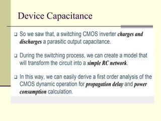
requisite). The CMOS inverter: - Voltage Transfer
Characteristics, SPICE Description, Static Behavior - Switching
Threshold - Noise Margins, Dynamic behavior - Device
Capacitances - Propagation Delay - Power Consumption.
Module 2: CMOS fabrication Processes: -N-Tub, P-Tub and
Twin Tub. MOS Circuit Layout - Stick diagrams, Layout design
rules, Transistor layout - PMOS and NMOS, Gate Layout -
Inverter, NAND, NOR and XOR, Layout generation using
MICROWIND tool (For Assignments/Projects only).
4. Overview of CMOS device
fundamentals (Pre-requisite)
Integrated circuits: many transistors on one
chip.
Very Large Scale Integration (VLSI)
Complementary Metal Oxide Semiconductor
(CMOS)
Fast, cheap, “low-power” transistors circuits
6. Digression: Silicon Semiconductors
Modern electronic chips are built mostly on silicon substrates
Silicon is a Group IV semiconducting material
crystal lattice: covalent bonds hold each atom to four neighbors
Si Si
Si
Si Si
Si
Si Si
Si
http://onlineheavytheory.net/silicon.html
7. Dopants
Silicon is a semiconductor at room temperature
Pure silicon has few free carriers and conducts poorly
Adding dopants increases the conductivity drastically
Dopant from Group V (e.g. As, P): extra electron (n-
type)
Dopant from Group III (e.g. B, Al): missing electron,
called hole (p-type)
As Si
Si
Si Si
Si
Si Si
Si
B Si
Si
Si Si
Si
Si Si
Si
-
+
+
-
8. p-n Junctions
First semiconductor (two terminal) devices
A junction between p-type and n-type
semiconductor forms a diode.
Current flows only in one direction
p-type n-type
anode cathode
9. A Brief History
Invention of the Transistor
Vacuum tubes ruled in first half of 20th
century Large,
expensive, power-hungry, unreliable
1947: first point contact transistor (3 terminal devices)
Shockley, Bardeen and Brattain at Bell Labs
10. A Brief History, contd..
1958: First integrated circuit
Flip-flop using two transistors
Built by Jack Kilby (Nobel Laureate) at Texas Instruments
Robert Noyce (Fairchild) is also considered as a co-inventor
smithsonianchips.si.edu/ augarten/
Kilby’s IC
11. A Brief History, contd.
First Planer IC built in 1961
2003
Intel Pentium 4 processor (55 million transistors)
512 Mbit DRAM (> 0.5 billion transistors)
53% compound annual growth rate over 45 years
No other technology has grown so fast so long
Driven by miniaturization of transistors
Smaller is cheaper, faster, lower in power!
Revolutionary effects on society
12. 1970’s processes usually had only nMOS transistors
Inexpensive, but consume power while idle
1980s-present: CMOS processes for low idle power
MOS Integrated Circuits
Intel 1101 256-bit SRAM Intel 4004 4-bit Proc
13. Moore’s Law
1965: Gordon Moore plotted transistor on each chip
Fit straight line on semilog scale
Transistor counts have doubled every 26 months
Year
Transistors
4004
8008
8080
8086
80286
Intel386
Intel486
Pentium
Pentium Pro
Pentium II
Pentium III
Pentium 4
1,000
10,000
100,000
1,000,000
10,000,000
100,000,000
1,000,000,000
1970 1975 1980 1985 1990 1995 2000
Integration Levels
SSI: 10 gates
MSI: 1000 gates
LSI: 10,000 gates
VLSI: > 10k gates
http://www.intel.com/technology/silicon/mooreslaw/
17. Transistor Types
Bipolar transistors
npn or pnp silicon structure
Small current into very thin base layer controls large
currents between emitter and collector
Base currents limit integration density
Metal Oxide Semiconductor Field Effect Transistors
nMOS and pMOS MOSFETS
Voltage applied to insulated gate controls current
between source and drain
Low power allows very high integration
First patent in the ’20s in USA and Germany
Not widely used until the ’60s or ’70s
18. MOS Transistors
Four terminal device: gate, source, drain, body
Gate – oxide – body stack looks like a capacitor
Gate and body are conductors (body is also called the substrate)
SiO2 (oxide) is a “good” insulator (separates the gate from the body
Called metal–oxide–semiconductor (MOS) capacitor, even though
gate is mostly made of poly-crystalline silicon (polysilicon)
n+
p
Gate
Source Drain
bulk Si
SiO2
Polysilicon
n+
SiO2
n
Gate
Source Drain
bulk Si
Polysilicon
p+ p+
NMOS PMOS
19. NMOS Operation
Body is commonly tied to ground (0 V)
Drain is at a higher voltage than Source
When the gate is at a low voltage:
P-type body is at low voltage
Source-body and drain-body “diodes” are OFF
No current flows, transistor is OFF
n+
p
Gate
Source Drain
bulk Si
SiO2
Polysilicon
n+
D
0
S
20. NMOS Operation Cont.
When the gate is at a high voltage: Positive charge
on gate of MOS capacitor
Negative charge is attracted to body under the gate
Inverts a channel under gate to “n-type” (N-channel, hence
called the NMOS) if the gate voltage is above a threshold
voltage (VT)
Now current can flow through “n-type” silicon from source
through channel to drain, transistor is ON
n+
p
Gate
Source Drain
bulk Si
SiO2
Polysilicon
n+
D
1
S
21. PMOS Transistor
Similar, but doping and voltages reversed
Body tied to high voltage (VDD)
Drain is at a lower voltage than the Source
Gate low: transistor ON
Gate high: transistor OFF
Bubble indicates inverted behavior
SiO2
n
Gate
Source Drain
bulk Si
Polysilicon
p+ p+
22. Power Supply Voltage
GND = 0 V
In 1980’s, VDD = 5V
VDD has decreased in modern processes
High VDD would damage modern tiny transistors
Lower VDD saves power
VDD = 3.3, 2.5, 1.8, 1.5, 1.2, 1.0,
Effective power supply voltage can be lower due
to IR drop across the power grid.
23. Transistors as Switches
In Digital circuits, MOS transistors are
electrically controlled switches
Voltage at gate controls path from source to
drain
g
s
d
g = 0
s
d
g = 1
s
d
g
s
d
s
d
s
d
nMOS
pMOS
OFF
ON
ON
OFF
33. 3-input NAND Gate
Y is pulled low if ALL inputs are 1
Y is pulled high if ANY input is 0
A
B
Y
C
34. CMOS Fabrication
CMOS transistors are fabricated on silicon
wafer
Wafers diameters (200-300 mm)
Lithography process similar to printing press
On each step, different materials are
deposited, or patterned or etched
Easiest to understand by viewing both top
and cross-section of wafer in a simplified
manufacturing process
37. Voltage Transfer Characteristics,
Region-1
In this region the input is in the range of (0,Vtn).
Since the input voltage is less than Vtn, the NMOS
is in cutoff region. No current flows from Vdd to
Vss, The entire Vdd will appear at the Output
terminal.
NMOS is in cutoff as Vgs < Vtn
PMOS is in linear as Vgsp < Vtp and Vdsp > Vgsp
-Vtp.
Zero current flows from supply voltage and the
power dissipation is zero.
Region-2
In this region the input is in the range of
(Vtn,Vdd/2). Since the input voltage is greater than
Vtn the NMOS is conducting and it jumps to
saturation as it has large Vds across it(Vout is
high). PMOS still remains in the linear region.
NMOS is in saturation as Vgs > Vtn and Vout >Vin
- Vtn.
PMOS is in linear region as Vdsp > Vgsp -Vtp.
since both the transistors are conducting some
amount of current flows from supply in this region.
38. Voltage Transfer Characteristics,
Region-3
In this region the input voltage is Vdd/2. At this point
the output voltage is also Vdd/2 as one can see in
figure-2. At this voltage both the NMOS and PMOS
are in saturation and the output drops drastically from
Vdd to Vdd/2. At this point a large amount of current
flows from the supply. Most of the power consumed in
CMOS inverter is at this point. So care should be
taken that the Input should not stay at Vdd/2 for more
amount of time.
NMOS is in saturation as Vgs > Vtn and Vout >Vin -
Vtn.
PMOS is in saturation as Vgsp < Vtp and Vdsp < Vgsp
-Vtp.
Large amount of current is drawn from supply and
hence large power dissipation.
39. Region-4
In this region the input voltage is in the
range of (Vdd/2 , Vdd-Vtp). Here the
PMOS remains in saturation as Vout < Vin
- Vtp and Vgsp < Vtp. But the NMOS
moves from saturation to linear region
since the drain to source voltage now is
less than Vgsn-Vtn.
NMOS is in linear as Vgs > Vtn and Vout <
Vin - Vtn.
PMOS is in saturation as Vgsp < Vtp and
Vdsp < Vgsp -Vtp.
A medium amount of current is drawn as
NMOS is in linear region and power
dissipation is low.
Voltage Transfer Characteristics,
40. Voltage Transfer Characteristics,
Region-5
In this region the input voltage is in the range of
(Vdd-Vtp,Vdd). Here the PMOS moves from
saturation to cutoff as the Vgsp is so high that
Vgsp > Vtp. The NMOS still remains in linear as
the drain to source voltage now is less than
Vgsn-Vtn.
NMOS is in linear as Vgs > Vtn and Vout < Vin -
Vtn.
PMOS is in cutoff as Vgsp > Vtp.
Zero current flows from the supply and so the
power dissipation is zero.
Now that we have clearly understood the voltage
transfer characteristics and operation of an
NMOS, we will discuss how to alter the transfer
characteristics of any CMOS gate in the next
article.