


ARC_INTRODUCTION OF EMBEDDED SYSTEMS(UNIT 1).pdf
- 2. SYLLABUS UNIT 1 Introduction: Embedded Systems and general purpose computer systems, history, classifications, applications and purpose of embedded systems Core of embedded systems: microprocessors and microcontrollers, RISC and CISC controllers, Big endian and Little endian processors, Application specific ICs, Programmable logic devices, COTS, sensors and actuators, communication interface, embedded firmware, other system components. Characteristics and quality attributes of embedded systems: Characteristics, operational and non- operational quality attributes.
- 3. CHP-1 EMBEDDED SYSTEMS something that is attached to another thing A system is a collection of elements or components that are organized for a common purpose. An Embedded System is an electronic/electro-mechanical system designed to perform a specific function and is a combination of both hardware and firmware(software).
- 4. Example : Washing Machine Hardware: Buttons, Displays, buzzers, electronic circuitry. Software: chip on circuit which controls and monitors various operation Mechanical Components: Internals of washing machine to wash , input and output control of water
- 5. 1. Computer: A computer is a combination of hardware and software resources that integrate together and provides various functionalities to the user. 2. Embedded Device : An embedded device is a part of an integrated system that is formed as a combination of computer hardware and software for a specific function and which can operate without human interaction. Criteria General Purpose Computing System Embedded System Content It is a combination of hardware, Software and a general purpose operating system for executing a variety of application It is a combination of special purpose hardware and embedded operating system for executing a specific set of application Operating System It has general purpose Operating system(GPOS) It may or may not have operating system Change Application are alterable by the user The firmware of embedded system is pre- programmed and it is not-alterable by the end-user Key Factor Performance is key factor Application specific is the key factor Power Consumption More Less generally they are battery operated. Response time Not Time-Critical It is time-critical in some application Examples Desktop, Laptop Air Conditioner, Refrigerator
- 6. CLASSIFICATION OF EMBEDDED SYSTEMS The classifications is based on the following criteria’s: A. On Generation B. On Complexing and Performance C. On Deterministic Behaviour D. On Triggering E. On Functional Requirement
- 7. CLASSIFICATION OF EMBEDDED SYSTEM BASED ON GENERATION 1.First Generation: Built around 8 bit microprocessor and 4 bit microcontroller Simple in hardware circuit and firmware developed. Example: Digital telephone keypads 2. Second Generation: Built around 16-bit microprocessor and 8 or 16 bit microcontroller They are more complex and powerful than 1G microprocessor and microcontroller Examples: data acquisition systems 3. Third Generation: Built around 32-bit microprocessor and 16-bitmicrocontroller DSP,ASIC Examples: Robotics,Media 4. Fourth Generation: Built around 64-bit microprocessor and 32-bit microcontroller System on chip(SoC), Multicore processors evolved Highly complex and powerful Example: Smart phone
- 8. CLASSIFICATION OF EMBEDDED SYSTEM BASED ON COMPLEXITY AND PERFORMANCE 1. Small-Scale(Eg : Electronic toy) Built around low performance and low cost 8-bit or 16-bit micro-controller/microprocessor. They can be powered by a battery. May or may not contain OS for its functioning. Simple in application need Performance not time-critical 2. Medium-Scale(Eg: Industrial machines) Built around medium performance and low cost 16-bit or 32-bit micro-controller/microprocessor. They usually contain embedded OS for functioning. Slightly complex in hardware and firmware requirement Java, C, C++ are the programming languages are used to develop medium scale embedded systems. 3. Large-Scale(Eg: Mission Critical Applications) Highly complex hardware and firmware Built around 32 or 64 bit RISC processors/controllers or multicore processors and programmable logic devices Response is time-critical Contains RTOS for task scheduling, prioritization and management
- 9. CLASSIFICATION OF EMBEDDED SYSTEM BASED ON DETERMINISTIC BEHAVIOUR This classification is applicable for Real Time Systems The task execution behaviour for embedded systems may be deterministic or non-deterministic Based on execution behaviour Real Time embedded systems are divided into Hard and Soft
- 10. CLASSIFICATION OF EMBEDDED SYSTEM BASED ON TRIGGERING Embedded Systems which are reactive in nature can be based on triggering . Reactive systems can be : Event triggered Time trigged
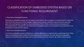
- 11. CLASSIFICATION OF EMBEDDED SYSTEM BASED ON FUNCTIONAL REQUIREMENT 1. Stand Alone Embedded Systems Stand alone embedded systems do not require a host system like a computer, it works by itself. It takes the input from the input ports either analog or digital and processes, calculates and converts the data and gives the resulting data through the connected device-Which either controls, drives and displays the connected devices. Examples for the stand alone embedded systems are microwave ovens,calculators and temperature measurement systems. 2. Real Time Embedded Systems A real time embedded system is defined as, a system which gives a required o/p in a particular time. These types of embedded systems follow the time deadlines for completion of a task. Real time embedded systems are classified into two types such as soft and hard real time systems. Eg: Traffic Control System
- 12. CLASSIFICATION OF EMBEDDED SYSTEM BASED ON FUNCTIONAL REQUIREMENT 3. Networked Embedded Systems These types of embedded systems are related to a network to access the resources. The connected network can be LAN, WAN or the internet. The connection can be any wired or wireless. This type of embedded system is the fastest growing area in embedded system applications. The embedded web server is a type of system wherein all embedded devices are connected to a web server and accessed and controlled by a web browser. Example for the LAN networked embedded system is a home security system wherein all sensors are connected and run on the protocol TCP/IP. Eg:ATM 4. Mobile Embedded Systems Mobile embedded systems are used in portable embedded devices like cell phones, mobiles etc. The basic limitation of these devices is the other resources and limitation of memory.
- 13. PURPOSE OF EMBEDDED SYSTEMS 1. Data Collection/Storage/Representation 2. Data Communication 3. Data (Signal) Processing 4. Monitoring 5. Control 6. Application Specific user interface
- 14. 1. DATA COLLECTION/STORAGE/REPRESENTATION Embedded Systems designed for the purpose of data collection performs acquisition of data from the external world. Data collection is usually done for storage, analysis, manipulation and transmission. Data can be digital(discrete) or analog (continuous) ES with analog data capturing techniques collect data directly in the form of analog signal whereas embedded system with digital data collection mechanism converts the analog signal to digital using analog to digital convertors If the data is digital it can be directly captured by digital ES Eg: Digital Camera Images are captured those may be stored within the memory of the camera. The captured image can also be presented to user through a graphic LCD unit
- 15. 2. DATA COMMUNICATION Embedded data communication systems are deployed in applications from complex satellite communication to simple home networking systems The transmission of data id achieved either by wire-line medium or by a wire-less medium Data can either be transmitted by analog means or by digital means Wireless modules-Bluetooth , Wi-Fi Wire-line modules-USB,TCP/IP Eg: Network hubs,routers,switches
- 16. 3.DIGITAL SIGNAL PROCESSING ES with signal processing functionalities are employed in applications demanding signal processing like speech coding, audio video, etc Eg: digital hearing Aid 4.MONITORING Embedded products under medical domain are with monitoring functions. Eg: Electro Cardiogram machine, digital CRO, digital multimeters and logic analyzers
- 17. 5.CONTROL System with control functionality contains both sensors and actuators. Sensors are connected to the input port for capturing the changes in environmental variable and the actuators connected to the output port are controlled according to changes in the input variable. Eg: AC system 6.APPLICATION SPECIFIC USER INTERFACE Buttons, switches, keypad, lights, bells, display units Eg:Mobile phone
- 18. APPLICATION OF EMBEDDED SYSTEMS IN VARIOUS AREAS In Automobiles and in telecommunication In Smart Cards, Missiles and Satellites In peripherals and Computer Networking In Customer Electronics Motor and cruise control system Security Systems Displays and Monitors Digital Cameras Body or Engine safety Telephone and banking Networking Systems Set top Boxes Entertainment and multimedia in car Defense and Aerospace Image Processing High Definition TVs E-Com and mobile access Communication Network cards and printer DVDs Robotics in assembly line Scanners Wireless communication Routers and Switches Mobile Computing and networking
- 19. APPLICATION OF EMBEDDED SYSTEMS IN VARIOUS AREAS In Household Appliances In health care In Banking and Retail In Card Readers Washing Machine MRI( Magnetic Resonance Imaging) Automatic Teller Machine Barcode Refrigerator ECG(Electro-Cardio- Graphy) Cheque Collection Machine Smart Card Readers Air Conditioner CT(Computerized Tomography) Scan Machine Point of Sales RFID Readers Microwave Fire and Gas Alarms
- 20. CHAPTER-2 CORE OF EMBEDDED SYSTEM A typical Embedded system contains a single chip controller, which acts as the brain of the system
- 21. CORE OF ES FALLS INTO ANYONE OF THE FOLLOWING CATEGORIES: 1. General Purpose and domain specific processors Microprocessors Microcontrollers Digital Signal Processors 2. Application Specific Integrated Circuits(ASICs) 3. Programmable Logical Device (PLDs) 4. Commercial off-the-shelf Components(COTS)
- 22. GENERAL PURPOSE AND DOMAIN SPECIFIC PROCESSORS Almost 80% of embedded systems are processor/controller based. The processor may be Microprocessor/Microcontroller/DSP depending upon domain and application
- 23. MICROPROCESSOR Microprocessor is a silicon chip representing a CPU → ALU according to pre-defined set of instructions. In general CPU contains ALU,CU and working registers. A microprocessor is a dependent unit and it requires the combination of h/w like memory,timer unit and interrupt controller. Different instruction set and system architecture for microprocessor Developers of Microprocessors Intel Intel 4004 November 1971 Intel Intel 4040 1972 Intel Intel 8008 April 1972 Intel Intel 8080 April 1974 Motorola Motorola 6800 Intel Intel 8085 1976 Zilog Z80 July 1976
- 24. MICROCONTROLLER Microcontroller is a highly integrated chip that contains a CPU, scratchpad RAM, special and general purpose register arrays, on chip ROM/Flash memory for program storage, timer and interrupt control units and dedicated I/O Ports. Microcontroller considered as superset of microprocessor Microcontroller is independent so used more in ES TMS 1000 first Microcontroller In 1977 Intel entered Microcontroller market with a family of controller coming under umbrella named MCS-48 TM Intel 8048 intel’s first microcontroller. Intel came up with most powerful 8bit microcontroller domain-8051 family. The instruction set architecture of a microcontroller can RISC or CISC Intel 8051 is an example of general purpose application requirement whereas automotive AVR family from Atmel Corporation is an example of ASIP specially for automotive domain
- 26. HARVARD VS VON-NEUMANN ARCHITECTURE
- 27. RISC VS CISC RISC stands for Reduced Instruction Set Computing. CISC stands for Complex Instruction Set Computing
- 28. DIGITAL SIGNAL PROCESSORS Digital Signal Processors(DSPs) are powerful special purpose 8/16/32 bit designed specifically to meet the computational demands and power constraints of today’s embedded audio, video and communication application. DSPs implement algorithms in hardware which speeds up the execution whereas GPP implement algorithm in firmware and the speed execution depends primarily on the clock for the processors. DSP can be viewed as a microchip designed for performing high speed computational operations for addition, subtraction, multiplication and division. Eg where DSP is employed: Audio video signal processing Blackfin processors from analog devices is an example of DSP
- 29. DIGITAL SIGNAL PROCESSORS A typical DSP has following units: Program memory: Memory for storing program required by DSP to process the data Data memory: Working memory for storing temporary variables and data/signal to be processed. Computational Engine: Performs the signal processing in accordance with the stored program memory. It incorporates many specialised arithmetic units which operates simultaneously to increase the execution speed. It also incorporates multiple hardware shifters for shifting operands and thereby saves execution time I/O unit: Acts as an interface between outside world and DSP. Its responsible for capturing signals to be processes and delivering the processed signal.
- 30. ENDIANNESS Endianness specifies the order in which the data is stored in the memory by processor operations in a multi byte system(Processors whose word size is greater then one byte)
- 31. LOAD STORE OPERATION AND INSTRUCTION PIPELINING
- 32. APPLICATION SPECIFIC INTEGRATED CIRCUITS(ASICS) Application Specific Integrated Circuit (ASIC) is a microchip designed to perform a specific or unique application It integrates several functions into a single chip and there by reduces the system development cost. Most of the ASICS are proprietary products. As a single chip, ASIC consumes a very small area in the total system and thereby helps in the design of smaller systems with high capabilities/functionalities. ASICS can be pre-fabricated for a special application or it can be custom fabricated by using the com- ponents from a re-usable 'building block' library of components for a particular customer application Fabrication of ASICS requires a non-refundable initial investment for the process technology and configuration expenses. This investment is known as Non-Recurring Engineering Charge (NRE) and it is a one time investment. If the Non-Recurring Engineering Charges (NRE) is borne by a third party and the Application Specific Integrated Circuit (ASIC) is made openly available in the market, the ASIC is referred as Application Specific Standard Product (ASSP).
- 33. PROGRAMMABLE LOGIC DEVICES Logic devices provide specific functions, including device-to-device interfacing, data communication, signal processing, data display, timing and control operations, and almost every other function a system must perform. Logic devices can be classified into two broad categories-fixed and programmable. The circuits in a fixed logic device are permanent, they perform one function or set of functions-once manufactured, they cannot be changed. With programmable logic devices, designers use inexpensive software tools to quickly develop, simulate, and test their designs The PLD that is used for this prototyping is the exact same PLD that will be used in the final production of a piece of end equipment, such as a network router, a DSL modem, a DVD player, or an automotive navigation system. There are no NRE costs and the final design is completed much faster than that of a custom, fixed logic device. Once the design is final, customers can go into immediate production by simply programming as many PLDs as they need with the final software design file.
- 34. CPLDS AND FPGAS The two major types of programmable logic devices are Field Programmable Gate Arrays (FPGAs) and Complex Programmable Logic Devices (CPLDs). Of the two, FPGAS offer the highest amount of logic density, the most features, and the highest performance. The largest FPGA now shipping, part of the Xilinx VirtexTM line of devices, provides eight million "system gates" (the relative density of logic). These advanced devices also offer features such as built-in hardwired processors (such as the IBM power PC), substantial amounts of memory, clock management systems, and support for many of the latest, very fast device-to-device signaling technologies. FPGAs are used in a wide variety of applications ranging from data processing and storage, to instrumentation, telecommunications, and digital signal processing. CPLDs, by contrast, offer much smaller amounts of logic-up to about 10,000 gates. But CPLDs offer very predictable timing characteristics and are therefore ideal for critical control applications. CPLDS such as the Xilinx CoolRunnerTM series also require extremely low amounts of power and are very in- expensive, making them ideal for cost-sensitive, battery-operated, portable applications such as mobile phones and digital handheld assistants.
- 35. Advantages of PLD Programmable logic devices offer a number of important advantages over fixed logic devices, including: PLDS offer customers much more flexibility during the design cycle because design iterations are simply a matter of changing the programming file, and the results of design changes can be seen immediately in working parts. ⚫ PLDs do not require long lead times for prototypes or production parts-the PLDs are already on a distributor's shelf and ready for shipment. ⚫ PLDs do not require customers to pay for large NRE costs and purchase expensive mask sets-PLD suppliers incur those costs when they design their programmable devices and are able to amortize those costs over the multi-year lifespan of a given line of PLDS. ⚫ PLDs allow customers to order just the number of parts they need, when they need them, allowing them to control inventory. Customers who use fixed logic devices often end up with excess inventory which must be scrapped, or if demand for their product surges, they may be caught short of parts and face production delays. PLDS can be reprogrammed even after a piece of equipment is shipped to a customer.
- 36. COMMERCIAL OFF-THE-SHELF COMPONENTS (COTS) A Commercial Off-the-Shelf (COTS) product is one which is used 'as-is'. COTS products are designed in such a way to provide easy integration and interoperability with existing system components. The COTS component itself may be developed around a general purpose or domain specific processor or an Application Specific Integrated circuit or a programmable logic device. The major advantage of using COTS is that they are readily available in the market, are cheap and a developer can cut down his/her development time to a great extent. This in turn reduces the time to market your embedded systems.
- 37. The TCP/IP plug-in module available from various manufactures like 'WIZnet', 'Freescale', 'Dynalog', etc. are very good examples of COTS product This network plug-in module gives the TCP/IP connectivity to the system you are developing. There is no need to design this module yourself and write the firmware for the TCP/ IP protocol and data transfer. Everything will be readily supplied by the COTS manufacturer. The major drawback of using COTS components in embedded design is that the manufacturer of the COTS component may withdraw the product or discontinue the production of the COTS at any time if a rapid change in technology occurs, and this will adversely affect a commercial manufacturer of the embedded system which makes use of the specific COTS product.
- 38. SENSORS AND ACTUATORS An embedded system is in constant interaction with the Real world and the controlling/monitoring functions executed by the embedded system is achieved in accordance with the changes happening to the Real world. The changes in system environment or variables are detected by the sensors connected to the input port of the embedded system. If the embedded system is designed for any controlling purpose, the system will produce some changes in the controlling variable to bring the controlled variable to the desired value. It is achieved through an actuator connected to the output port of the embedded system. If the embedded system is designed for monitoring purpose only, then there is no need for including an actuator in the system. For example, take the case of an ECG machine
- 39. Sensors A sensor is a transducer device that converts energy from one form to another for any measurement or control purpose. Actuators Actuator is a form of transducer device (mechanical or electrical) which converts signals to corresponding physical action (motion). Actuator acts as an output device.
- 40. THE I/O SUBSYSTEM The I/O subsystem of the embedded system facilitates the interaction of the embedded system with the external world. The interaction happens through the sensors and actuators connect- ed to the input and output ports respectively of the embedded system. The sensors may not be directly interfaced to the input ports, instead they may be interfaced through signal conditioning and translating systems like ADC, optocouplers, etc. This section illustrates some of the sensors and actuators used in embedded systems and the I/O systems to facilitate the interaction of embedded systems with external world. The different I/O Subsystems are discussed in the following slides:
- 41. 1) LIGHT EMITTING DIODE (LED) Light Emitting Diode (LED) is an important output device for visual indication in any embedded system. LED can be used as an indicator for the status of various signals or situations. Typical examples are indicating the presence of power conditions like 'Device ON', 'Battery low' or 'Charging of battery' for a battery operated handheld embedded devices Light Emitting Diode is a p-n junction diode and it contains an anode and a cathode. For proper functioning of the LED, the anode of it should be connected to +ve terminal of the supply voltage and cathode to the -ve terminal of supply voltage. The current flowing through the LED must be limited to a value below the maximum current that it can conduct. A resister is used in series between the power supply and the LED to limit the current through the LED.
- 42. LEDs can be interfaced to the port pin of a processor/controller in two ways. In the first method, the anode is directly connected to the port pin and the port pin drives the LED. In this approach the port pin 'sources' current to the LED when the port pin is at logic High (Logic '1’). In the second method, the cathode of the LED is connected to the port pin of the processor/controller and the anode to the sup- ply voltage through a current limiting resistor. The LED is turned on when the port pin is at logic Low (Logic '0'). Here the port pin 'sinks' current.
- 43. 2) 7-SEGMENT LED DISPLAY The 7-segment LED display is an output device for displaying alpha numeric characters It contains 8 light-emitting diode (LED) segments arranged in a special form. Out of the 8 LED segments, 7 are used for displaying alpha numeric characters and 1 is used for representing 'decimal point' in decimal number display. Figure 2.14 explains the arrangement of LED segments in a 7-segment LED display. The LED segments are named A to G and the decimal point LED segment is named as DP. The LED segments A to G and DP should be lit accordingly to display numbers and characters. For example, for displaying the number 4 the segments F, G, B and C are lit. For displaying the character 'd’, the segments B, C, D, E and G are lit.
- 44. All these 8 LED segments need to be connected to one port of the processor/controller for displaying alpha numeric digits. The 7-segment LED displays are available in two different configurations, namely; Common Anode and Common Cathode. In the common anode configuration, the anodes of the 8 segments are connected commonly whereas in the common cathode configuration, the 8 LED segments share a common cathode line Based on the configuration of the 7-segment LED unit, the LED segment's anode or cathode is connected to the port of the processor/controller in the order 'A' segment to the least significant port pin and DP segment to the most significant port pin. 7-segment LED display is a popular choice for low cost embedded applications like, Public telephone call monitoring devices, point of sale terminals, etc.
- 45. 3) OPTOCOUPLER Optocoupler is a solid state device to isolate two parts of a circuit. Optocoupler combines an LED and a photo-transistor in a single housing (package). In electronic circuits, an optocoupler is used for suppressing interference in data communication, circuit isolation, high voltage separation, simultaneous separation and signal intensification, etc. Optocouplers can be used in either input circuits or in output circuits. Figure illustrates the usage of optocoupler in input circuit and output circuit of an embedded system with a microcontroller as the system core. Optocoupler is available as ICs from different semiconductor manufacturers. The MCT2M IC from Fairchild semiconductor is an example for optocoupler IC.
- 46. 4) RELAY Relay is an electro-mechanical device. In embedded application, the 'Relay' unit acts as dynamic path selectors for signals and power. The 'Relay' unit contains a relay coil made up of insulated wire on a metal core and a metal armature with one or more contacts. 'Relay' works on electromagnetic principle. When a voltage is applied to the relay coil, current flows through the coil, which in turn generates a magnetic field. The magnetic field attracts the armature core and moves the contact point. The movement of the contact point changes the power/signal flow path. 'Relays' are available in different configurations. Figure given below illustrates the widely used relay configurations for embedded applications.
- 47. 5) PIEZO BUZZER Piezo buzzer is a piezoelectric device for generating audio indications in embedded application. A piezoelectric buzzer contains a piezoelectric diaphragm which produces audible sound in response to the voltage applied to it. Piezoelectric buzzers are available in two types. 'Self- driving' and 'External driving’. The 'Self-driving' circuit contains all the necessary components to generate sound at a predefined tone. It will generate a tone on applying the voltage. External driving piezo buzzers supports the generation of different tones. The tone can be varied by applying a variable pulse train to the piezoelectric buzzer. A piezo buzzer can be directly interfaced to the port pin of the processor/control.
- 48. 6) PUSH BUTTON SWITCH It is an input device. Push button switch comes in two configurations, namely 'Push to Make' and 'Push to Break’. In the 'Push to Make' configuration, the switch is normally in the open state and it makes a circuit contact when it is pushed or pressed. In the 'Push to Break' configuration, the switch is normally in the closed state and it breaks the circuit contact when it is pushed or pressed. The push button stays in the 'closed' (For Push to Make type) or 'open' (For Push to Break type) state as long as it is kept in the pushed state and it breaks/makes the circuit connection when it is released. Push button is used for generating a momentary pulse. In embedded application push button is generally used as reset and start switch and pulse generator. The Push button is normally connected to the port pin of the host processor/controller. Depending on the way in which the push button interfaced to the controller, it can generate either a 'HIGH' pulse or a 'LOW' pulse. Figure 2.23 illustrates how the push button can be used for generating 'LOW' and 'HIGH' pulses.
- 49. 7) KEYBOARD Keyboard is an input device for user interfacing. If the number of keys required is very limited, push button switches can be used and they can be directly interfaced to the port pins for reading. Matrix keyboard is an optimum solution for handling large key requirements. It greatly reduces the number of interface connections. For example, for interfacing 16 keys, in the direct interfacing technique 16 port pins are required, whereas in the matrix keyboard only 8 lines are required. The 16 keys are arranged in a 4 column x 4 Row matrix. Figure 2.24 illustrates the connection of keys in a matrix keyboard. In a matrix keyboard, the keys are arranged in matrix fashion (i.e. they are connected in a row and column style). For detecting a key press, the keyboard uses the scanning technique, where each row of the matrix is pulled low and the columns are read. After reading the status of each columns corresponding to a row, the row is pulled high and the next row is pulled low and the status of the columns are read. This process is repeated until the scanning for all rows are completed. When a row is pulled low and if a key connected to the row is pressed, reading the column to which the key is connected will give logic 0. Since keys are mechanical devices, there is a possibility for de-bounce issues, which may give multiple key press effect for a single key press.
- 50. To prevent this, a proper key de-bouncing technique should be applied. Hardware key de-bouncer circuits and software key de-bounce techniques are the key de- bouncing techniques available. The software key de-bouncing technique doesn't require any additional hardware and is easy to implement. In the software de-bouncing technique, on detecting a key-press, the key is read again after a de-bounce delay. If the key press is a genuine one, the state of the key will remain as 'pressed' on the second read also. Pull-up resistors are connected to the column lines to limit the current that flows to the Row line on a key press.
- 51. 8)PROGRAMMABLE PERIPHERAL INTERFACE (PPI) Programmable Peripheral Interface (PPI) devices are used for extending the I/O capabilities of processors/controllers. Most of the processors/ controllers provide very limited number of I/O and data ports and at times it may require more number of I/O ports than the one supported by the controller/processor. A programmable peripheral interface device expands the I/O capabilities of the processor/controller. 82554 is a popular PPI device for 8bit processors/controllers. 82554 supports 24 1/O pins and these I/O pins can be grouped as either three 8-bit parallel ports (Port A, Port B and Port C) or two 8bit parallel ports (Port A and Port B) with Port C in any one of the following configurations: 1. As 8 individual I/O pins 2. Two 4bit ports namely Port CUPPER (Cu) and Port CLOWER (CL) This is configured by manipulating the control register of 8255A. The control register holds the con- figuration for Port A, Port B and Port C. The bit details of control register is given below:
- 52. 9) STEPPER MOTOR Stepper Motor A stepper motor is an electro-mechanical device which generates discrete displacement (motion) in response to de electrical signals. The de motor produces continuous rotation on applying dc voltage whereas a stepper motor produces discrete rotation in response to the de voltage applied to it. The paper feed mechanism of a printer/fax makes use of stepper motors for its functioning. Based on the coil winding arrangements, a two-phase stepper motor is classified into two. They are: 1. Unipolar: A unipolar stepper motor contains two windings per phase. The direction of rotation (clockwise or anticlockwise) of a stepper motor is controlled by changing the direction of current flow. Current in one direction flows through one coil and in the opposite direction flows through the other coil. 2. Bipolar: A bipolar stepper motor contains single winding per phase. For reversing the motor rotation the current flow through the windings is reversed dynamically. The different stepping modes supported by stepper motor are explained below. Full Step: In the full step mode both the phases are energised simultaneously. Wave Step: In the wave step mode only one phase is energised at a time and each coils of the phase is energised alternatively. Half Step: It uses the combination of wave and full step. It has the highest torque and stability.
- 53. COMMUNICATION INTERFACE Communication interface is essential for communicating with various subsystems of the embedded system and with the external world. For an embedded product, the communication interface can be viewed in two different perspectives:- Device/board level communication interface (Onboard Communication Interface) Product level communication interface (External Communication Interface)
- 54. ONBOARD COMMUNICATION INTERFACES Onboard Communication Interface refers to the different communication channels/buses for interconnecting the various integrated circuits and other peripherals within the embedded system. 1. Inter Integrated Circuit (12C) Bus The Inter Integrated Circuit Bus is a synchronous bi-directional half duplex (one-directional communication at a given point of time) two wire serial interface bus. The I2C bus comprise of two bus lines, namely; Serial Clock-SCL and Serial Data-SDA. SCL line is responsible for generating synchronisation clock pulses and SDA is responsible for transmitting the serial data across devices. Devices connected to the I2C bus can act as either 'Master' device or 'Slave' device. synchronisation clock signal is generated by the 'Master' device only. I2C supports multi masters on the same bus. 12C bus supports three different data rates. They are: Standard mode (Data rate up to 100kbits/sec 100 kbps)), Fast mode (Data rate up to 400kbits/sec (400 kbps)) and High speed mode (Data rate up to 5.4Mbits/sec (3.4 Mbps)).
- 55. 1. The master device pulls the clock line (SCL) of the bus to 'HIGH' 2. The master device pulls the data line (SDA) 'LOW', when the SCL line is at logic 'HIGH' (This is the 'Start' condition for data transfer) 3. The master device sends the address (7 bit or 10 bit wide) of the 'slave' device to which it wants to communicate, over the SDA line. Clock pulses are generated at the SCL line for synchronising the bit reception by the slave device. The MSB of the data is always transmitted first. The data in the bus is valid during the 'HIGH' period of the clock signal 4. The master device sends the Read or Write bit (Bit value = 1 Read operation; Bit value = 0 Write operation) according to the requirement 5. The master device waits for the acknowledgement bit from the slave device whose address is sent on the bus along with the Read/Write operation command. Slave devices connected to the bus compares the address received with the address assigned to them 6. The slave device with the address requested by the master device responds by sending an acknowledge bit (Bit value = 1) over the SDA line 7. Upon receiving the acknowledge bit, the Master device sends the 8bit data to the slave device over SDA line, if the requested operation is 'Write to device'. If the requested operation is 'Read from device', the slave device sends data to the master over the SDA line 8. The master device waits for the acknowledgement bit from the device upon byte transfer complete for a write operation and sends an acknowledge bit to the Slave device for a read operation 9. The master device terminates the transfer by pulling the SDA line 'HIGH' when the clock line SCL is at logic 'HIGH' (Indicating the 'STOP' condition)
- 56. 2. SERIAL PERIPHERAL INTERFACE (SPI) BUS The Serial Peripheral Interface Bus (SPI) is a synchronous bi-directional full duplex four-wire serial interface bus. The concept of SPI was introduced by Motorola. SPI is a single master multi-slave system. SPI requires four signal lines for communication. They are: The master device is responsible for generating the clock signal. It selects the required slave device by asserting the corresponding slave device's slave select signal 'LOW'. The data out line (MISO) of all the slave devices when not selected floats at high impedance state. The serial data transmission through SPI bus is fully configurable. SPI works on the principle of 'Shift Register'. The master and slave devices contain a special shift register for the data to transmit or receive.
- 57. During transmission from the master to slave, the data in the master's shift register is shifted out to the MOSI pin and it enters the shift register of the slave device through the MOSI pin of the slave device. At the same time the shifted out data bit from the slave device's shift register enters the shift register of the master device through MISO pin. The shift registers of 'master' and 'slave' devices form a circular buffer. For some devices, the decision on whether the LS/MS bit of data needs to be sent out first is configurable through configuration register When compared to I2C, SPI bus is most suitable for applications requiring transfer of data in 'streams'. The only limitation is SPI doesn't support an acknowledgement mechanism.
- 58. 3.UNIVERSAL ASYNCHRONOUS RECEIVER TRANSMITTER (UART) Universal Asynchronous Receiver Transmitter (UART) based data transmission is an asynchronous form of serial data transmission. Instead it relies upon the pre-defined agreement between the transmitting device and receiving device. The serial communication settings for both transmitter and receiver should be set as identical. The start and stop of communication is indicated through inserting special bits in the data stream. While sending a byte of data, a start bit is added first and a stop bit is added at the end of the bit stream. The least significant bit of the data byte follows the 'start' bit. The 'start' bit informs the receiver that a data byte is about to arrive. The receiver device starts polling its 'receive line' as per the baudrate settings. If the baudrate is 'x' bits per second, the time slot available for one bit is 1/x seconds. If parity is enabled for communication, the UART of the transmitting device adds a parity bit (bit value is 1 for odd number of 1s in the transmitted bit stream and 0 for even number of 1s) The UART of the receiving device discards the 'Start', 'Stop' and 'Parity' bit from the received bit stream and converts the received serial bit data to a word
- 60. 4. 1-WIRE INTERFACE 1-wire interface is an asynchronous half-duplex communication protocol developed by Maxim Dallas Semiconductor It is also known as Dallas 1-Wire® protocol. It makes use of only a single signal line (wire) called DQ for communication and follows the master-slave communication model. The 1-wire interface supports a single master and one or more slave devices on the bus. Every 1-wire device contains a globally unique 64bit identification number stored within it. This unique identification number can be used for addressing individual devices present on the bus in case there are multiple slave devices connected to the 1-wire bus. The identifier has three parts: an 8bit family code, a 48bit serial number and an 8bit CRC computed from the first 56 bits. 1. The master device sends a 'Reset' pulse on the 1-wire bus. 2. The slave device(s) present on the bus respond with a 'Presence' pulse. 3. The master device sends a ROM command (Net Address Command followed by the 64bit address of the device). This addresses the slave device(s) to which it wants to initiate a communication. 4. The master device sends a read/write function command to read/write the internal memory or register of the slave device. 5. The master initiates a Read data/Write data from the device or to the device All communication over the 1-wire bus is master initiated.
- 62. 5. PARALLEL INTERFACE The on-board parallel interface is normally used for communicating with peripheral devices which are memory mapped to the host of the system. The host processor/controller of the embedded system contains a parallel bus and the device which supports parallel bus can directly connect to this bus system. The communication through the parallel bus is controlled by the control signal interface between the device and the host. The 'Control Signals' for communication includes 'Read/ Write' signal and device select signal. The device normally contains a device select line and the device becomes active only when this line is asserted by the host processor. The direction of data transfer (Host to Device or Device to Host) can be controlled through the control signal lines for 'Read' and 'Write". Only the host processor has control over the 'Read' and 'Write' control signals. The device is normally memory mapped to the host processor and a range of address is assigned to it. An address decoder circuit is used for generating the chip select signal for the device.
- 63. When the address selected by the processor is within the range assigned for the device, the decoder circuit activates the chip select line and thereby the device becomes active. The processor then can read or write from or to the device by asserting the corresponding control line (RD) and WR respectively
- 64. EXTERNAL COMMUNICATION INTERFACES 1. RS-232 C & RS-485 The External Communication Interface refers to the different communication channels/buses used by the embedded system to communicate with the external world. RS-232 C (Recommended Standard number 232, revision C from the Electronic Industry Association) is a legacy, full duplex, wired, asynchronous serial communication interface RS-232 extends the UART communication signals for external data communication. UART uses the standard TTL/CMOS logic (Logic 'High' corresponds to bit value 1 and Logic 'Low' corresponds to bit value 0) for bit transmission whereas RS-232 follows the EIA standard for bit transmission. As per the EIA standard, a logic '0' is represented with voltage between +3 and +25V and a logic '1' is represented with voltage between -3 and -25V. In EIA standard, logic '0' is known as 'Space' and logic '1' as 'Mark’. RS-232 supports two different types of connectors, namely; DB-9: 9-Pin connector and DB-25: 25-Pin connector
- 65. RS-232 is a point-to-point communication interface and the devices involved in RS-232 communication are called 'Data Terminal Equipment (DTE)' and 'Data Communication Equipment (DCE) The RXD pin of DCE should be connected to the TXD pin of DTE and vice versa for proper data transmission. The Request To Send (RTS) and Clear To Send (CTS) signals co-ordinate the communication between DTE and DCE. Whenever the DTE has a data to send, it activates the RTS line and if the DCE is ready to accept the data, it activates the CTS line. The Data Terminal Ready (DTR) signal is activated by DTE when it is ready to accept data. The Data Set Ready (DSR) is activated by DCE when it is ready for establishing a communication link. DTR should be in the activated state before the activation of DSR. The Data Carrier Detect (DCD) control signal is used by the DCE to indicate the DTE that a good signal is being received. Ring Indicator (RI) is a modem specific signal line for indicating an incoming call on the telephone line. RS-232 supports only point-to-point communication and not suitable for multi-drop communication. RS-485 is the enhanced version of RS-422 and it supports multi-drop communication with up to 32 transmitting devices (drivers) and 32 receiving devices on the bus. The communication between devices in the bus uses the 'addressing' mechanism to identify slave devices.
- 66. 2.UNIVERSAL SERIAL BUS (USB) Universal Serial Bus (USB) is a wired high speed serial bus for data communication. The first version of USB (USB1.0) was released in 1995 and was created by the USB core group members consisting of Intel, Microsoft, IBM, Compaq, Digital and Northern Tele- com. The USB communication system follows a star topology with a USB host at the centre and one or more USB peripheral devices/USB hosts connected to it. A USB host can support connections up to 127, including slave peripheral devices and other USB hosts USB transmits data in packet format. Each data packet has a standard format. The USB communication is a host initiated one. The physical connection between a USB peripheral device and master device is established with a USB cable The USB standard uses two different types of connector at the ends of the USB cable for connecting the USB peripheral device and host device. "Type A' connector is used for upstream connection (connection with host) and Type B connector is used for downstream connection (connection with slave device). The USB connector present in desktop PCs or laptops are examples for 'Type A' USB connector. Both Type A and Type B connectors contain 4 pins for communication.
- 67. USB uses differential signals for data transmission. USB interface has the ability to supply power to the connecting devices Each USB device contains a Product ID (PID) and a Vendor ID (VID). USB supports four different types of data transfers, namely;- Control transfer is used by USB system software to query, configure and issue commands to the USB device. Bulk transfer is used for sending a block of data to a device. Bulk transfer supports error checking and correction. Transferring data to a printer is an example for bulk transfer. Isochronous data transfer is used for real-time data communication. In Isochronous transfer, data is transmitted as streams in real-time. Isochronous transfer doesn't support error checking and re-transmission of data in case of any transmission loss. All streaming devices like audio devices and medical equipment for data collection make use of the isochronous transfer. Interrupt transfer is used for transferring small amount of data. Interrupt transfer mechanism makes use of polling technique to see whether the USB device has any data to send. Devices like Mouse and Keyboard, which transmits fewer amounts of data, uses Interrupt transfer. Presently USB supports four different data rates namely; Low Speed (1.5Mbps), Full Speed (12Mbps), High Speed (480Mbps) and Super Speed (4.8Gbps). The Low Speed and Full Speed specifications are defined by USB 1.0 and the High Speed specification is defined by USB 2.0. USB 3.0 defines the specifications for Super Speed.
- 68. 3. IEEE 1394 (FIREWIRE) IEEE 1394 is a wired, isochronous high speed serial communication bus. It is also known as High Performance Serial Bus (HPSB). The IEEE 1394 uses differential data transfer (The information is sent using differential signals through a pair of twisted cables. It increases the noise immunity) and the interface cable supports 3 types of connectors, namely; 4-pin connector, 6-pin connector (alpha connector) and 9 pin connector (beta connector). The 6 and 9 pin connectors carry power also to support external devices It can supply unregulated power in the range of 24 to 30V. There are two differential data transfer lines A and B per connector. In a 1394 cable, normally the differential lines of A are connected to B (TPA+ to TPB+ and TPA-to TPB-) and vice versa. 1394 is a popular communication interface for connecting embedded devices like Digital Camera, Camcorder, Scanners to desktop computers for data transfer and storage. IEEE 1394 doesn't require a host for communicating between devices. For example, you can directly connect a scanner with a printer for printing.
- 69. 4. INFRARED (IRDA) Infrared (IrDA) is a serial, half duplex, line of sight based wireless technology for data communication between devices. Infrared communication technique uses infrared waves of the electromagnetic spectrum for transmitting the data. IrDA supports point-point and point-to-multipoint communication, provided all devices involved in the communication are within the line of sight. The typical communication range for IrDA lies in the range 10 cm to 1 m. Depending on the speed of data transmission IR is classified into Serial IR (SIR), Medium IR (MIR), Fast IR (FIR), Very Fast IR (VFIR) and Ultra Fast IR (UFIR). SIR supports transmission rates ranging from 9600bps to 115.2kbps. MIR supports data rates of 0.576Mbps and 1.152Mbps. FIR supports data rates up to 4Mbps. VFIR is designed to support high data rates up to 16Mbps. IrDA communication involves a transmitter unit for transmitting the data over IR and a receiver for receiving the data. Infrared Light Emitting Diode (LED) is the IR source for transmitter and at the receiving end a photodiode acts as the receiver. Certain devices like a TV remote control always require unidirectional communication and so they contain either the transmitter or receiver unit 'Infra-red Data Association' is the regulatory body responsible for de- fining and licensing the specifications for IR data communication. IrDA communication has two essential parts; a physical link part and a protocol part.
- 71. 5.BLUETOOTH (BT) Bluetooth is a low cost, low power, short range wireless technology for data and voice communication. Bluetooth was first proposed by 'Ericsson' in 1994. Bluetooth operates at 2.4GHz of the Radio Frequency spectrum and uses the Frequency Hopping Spread Spectrum (FHSS) technique for communication. Literally it supports a data rate of up to 1Mbps and a range of approximately 30 feet for data communication. Like IrDA, Bluetooth communication also has two essential parts; a physical link part and a protocol part. Bluetooth enabled devices essentially contain a Bluetooth wireless radio for the transmission and reception of data. The rules governing the Bluetooth communication is implemented in the 'Bluetooth protocol stack'. The Bluetooth communication IC holds the stack. Each Bluetooth device will have a 48 bit unique identification number. Bluetooth communication follows packet based data transfer.
- 72. Bluetooth supports point-to-point (device to device) and point-to-multipoint (device to multiple device broadcasting) wireless communication. The point-to-point communication follows the master- slave relationship. A Bluetooth device can function as either master or slave. When a network is formed with one Bluetooth device as master and more than one device as slaves, it is called a Piconet. A Piconet supports a maximum of seven slave devices. Bluetooth is the favourite choice for short range data communication in handheld embedded devices. Bluetooth technology is very popular among cell phone users as they are the easiest communication channel for transferring ringtones, music files, pictures, media files, etc. between neighbouring Blue- tooth enabled phones. The specifications for Bluetooth communication is defined and licensed by the standards body 'Blue- tooth Special Interest Group (SIG)'.
- 73. 6. WI-FI Wi-Fi or Wireless Fidelity is the popular wireless communication technique for networked communication of devices. Wi-Fi follows the IEEE 802.11 standard. Wi-Fi based communications require an intermediate agent called Wi-Fi router/Wireless Access point to manage the communications. The Wi-Fi router is responsible for restricting the access to a network, assigning IP address to devices on the network, routing data packets to the intended devices on the network. Wi-Fi enabled devices contain a wireless adaptor for transmitting and receiving data in the form of radio signals through an antenna. The hardware part of it is known as Wi-Fi Radio. For communicating with devices over a Wi-Fi network, the device when its Wi-Fi radio is turned ON, searches the available Wi-Fi network in its vicinity and lists out the Service Set Identifier (SSID) of the available networks. If the network is security enabled, a password may be required to connect to a particular SSID. Wi-Fi employs different security mechanisms like Wired Equivalency Privacy (WEP) Wireless Protected Access (WPA), etc. for securing the data communication. Wi-Fi standards (802.11a/b/g/n)
- 74. 7. ZIGBEE ZigBee is a low power, low cost, wireless network communication protocol based on the IEEE 802.15.4-2006 standard. ZigBee is targeted for low power, low data rate and secure applications for Wireless Personal Area Networking (WPAN). ZigBee operates worldwide at the unlicensed bands of Radio spectrum, mainly at 2.400 to 2.484 GHz, 902 to 928 MHz and 868.0 to 868.6 MHz. ZigBee Supports an operating distance of up to 100 metres and a data rate of 20 to 250Kbps. In the ZigBee terminology, each ZigBee device falls under any one of the following ZigBee device category. ZigBee Coordinator (ZC)/Network Coordinator: The ZigBee coordinator acts as the root of the ZigBee network. The ZC is responsible for initiating the ZigBee network and it has the capability to store information about the network. ZigBee Router (ZR)/Full function Device (FFD): Responsible for passing information from device to another device or to another ZR. ZigBee End Device (ZED)/Reduced Function Device (RFD): End device containing ZigBee functionality for data communication. It can talk only with a ZR or ZC and doesn't have the capability to act as a mediator for transferring data from one device to another.
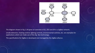
- 75. The diagram shown in Fig. 2.34 gives an overview of ZC, ZED and ZR in a ZigBee network. smoke detectors, heating control, lighting controls, environmental controls, etc. are examples for applications which can make use of the Zig- Bee technology. The specifications for ZigBee is developed and managed by the ZigBee alliance.
- 76. 8. GENERAL PACKET RADIO SERVICE (GPRS) General Packet Radio Service (GPRS) is a communication technique for transferring data over a mobile communication network like GSM. Data is sent as packets in GPRS communication. The transmitting device splits the data into several related packets. At the receiving end the data is re-constructed by combining the received data packets. GPRS supports a theoretical maximum transfer rate of 171.2kbps. In GPRS communication, the radio channel is concurrently shared between several users instead of dedicating a radio channel to a cell phone user. The GPRS communication divides the channel into 8 timeslots and transmits data over the available channel. GPRS supports Internet Protocol (IP), Point to Point Protocol (PPP) and X.25 protocols for communication. GPRS is mainly used by mobile enabled embedded devices for data communication. The device should support the necessary GPRS hardware like GPRS modem and GPRS radio. To accomplish GPRS based communication, the carrier network also should have support for GPRS communication.
- 77. EMBEDDED FIRMWARE 1. Write the program in high level languages like Embedded C/C++ using an Integrated Development Environment (The IDE will contain an editor, compiler, linker, debugger, simulator, etc. IDES are different for different family of processors/controllers. For example, Keil micro vision3 IDE is used for all family members of 8051 microcontroller, since it contains the generic 8051 compiler C51). 2. Write the program in Assembly language using the instructions supported by your application's target processor/controller. The instruction set for each family of processor/controller is different and the program written in either of the methods given above should be converted into a processor understandable machine code before loading it into the program memory. The process of converting the program written in either a high level language or processor/controller specific Assembly code to machine readable binary code is called 'HEX File Creation'.
- 78. OTHER SYSTEM COMPONENTS 1.RESET CIRCUIT The reset circuit is essential to ensure that the device is not operating at a voltage level where the device is not guaranteed to operate, during system power ON. The reset signal brings the internal registers and the different hardware systems of the processor/controller to a known state and starts the firmware execution from the reset vector The reset signal can be either active high (The processor undergoes reset when the reset pin of the processor is at logic high) or active low (The processor undergoes reset when the reset pin of the processor is at logic low). Since the processor operation is synchronised to a clock signal, the reset pulse should be wide enough to give time for the clock oscillator to stabilise before the internal reset state starts. Some microprocessors/controllers contain built-in internal reset circuitry and they don't require external reset circuitry.
- 79. 2.BROWN-OUT PROTECTION CIRCUIT Brown-out protection circuit prevents the processor/controller from unexpected program execution behaviour when the supply voltage to the processor/controller falls below a specified voltage. It is essential for battery powered devices since there are greater chances for the battery voltage to drop below the required threshold. The processor behaviour may not be predictable if the supply voltage falls below the recommended operating voltage. It may lead to situations like data corruption. A brown-out protection circuit holds the processor/controller in reset state, when the operating voltage falls below the threshold, until it rises above the threshold voltage. Certain processors/controllers support built in brown-out protection circuit which monitors the supply voltage internally. If the processor/controller doesn't integrate a built-in brown-out protection circuit, the same can be implemented using external passive circuits or supervisor ICs
- 80. 3.OSCILLATOR UNIT A microprocessor/microcontroller is a digital device made up of digital combinational and sequential circuits. The instruction execution of a microprocessor/controller occurs in sync with a clock signal The oscillator unit of the embedded system is responsible for generating the precise clock for the processor. Certain processors/controllers integrate a built-in oscillator unit and simply require an external ceramic resonator/quartz crystal for producing the necessary clock signals. Certain devices may not contain a built-in oscillator unit and require the clock pulses to be generated and supplied externally. Quartz crystal Oscillators are available in the form chips and they can be used for generating the clock pulses in such a cases. The speed of operation of a processor is primarily dependent on the clock frequency. However we cannot increase the clock frequency blindly for increasing the speed of execution. The power consumption increases with increase in clock frequency. The accuracy of program execution depends on the accuracy of the clock signal.
- 81. 4.REAL-TIME CLOCK (RTC) Real-Time Clock (RTC) is a system component responsible for keeping track of time. RTC holds information like current time (In hours, minutes and seconds) in 12 hour/24 hour format, date, month, year, day of the week, etc. and supplies timing reference to the system. RTC is intended to function even in the absence of power. RTCs are available in the form of Integrated Circuits from different semiconductor manufacturers like Maxim/Dallas, ST Microelectronics etc. The RTC chip contains a microchip for holding the time and date related information and backup battery cell for functioning in the absence of power, in a single IC package The OS kernel identifies the interrupt in terms of the Interrupt Request (IRQ) number generated by an interrupt controller. One IRQ can be assigned to the RTC interrupt and the kernel can perform necessary operations like system date time updation, managing software timers etc when an RTC timer tick interrupt occurs. The RTC can be configured to interrupt the processor at predefined intervals or to interrupt the processor when the RTC register reaches a specified value (used as alarm interrupt).
- 82. 5.WATCHDOG TIMER a watchdog is to monitor the firmware execution and reset the system processor/microcontroller when the program execution hangs up. A watchdog timer, or simply a watchdog, is a hardware timer for monitoring the firmware execution. Depending on the internal implementation, the watchdog timer increments or decrements a free running counter with each clock pulse and generates a reset signal to reset the processor if the count reaches zero for a down counting watchdog, or the highest count value for an upcounting watchdog. If the watchdog counter is in the enabled state, the firmware can write a zero (for upcounting watchdog implementation) to it before starting the execution of a piece of code (subroutine or portion of code which is susceptible to execution hang up) and the watchdog will start counting. If the firmware execution doesn't complete due to malfunctioning, within the time required by the watchdog to reach the maximum count, the counter will generate a reset pulse and this will reset the processor (if it is connected to the reset line of the processor). If the firmware execution completes before the expiration of the watchdog timer you can reset the count by writing a 0 (for an upcounting watchdog timer) to the watchdog timer register.
- 83. CHAPTER 3 CHARACTERISTICS AND QUALITY ATTRIBUTES OF EMBEDDED SYSTEMS CHARACTERISTICS OF AN EMBEDDED SYSTEM Unlike general purpose computing systems, embedded systems possess certain specific characteristics and these characteristics are unique to each embedded system. Some of the important characteristics of an embedded system are: 1. Application and domain specific 2. Reactive and Real Time 3. Operates in harsh environments 4. Distributed 5. Small size and weight 6. Power concerns
- 84. 1.APPLICATION AND DOMAIN SPECIFIC If you closely observe any embedded system, you will find that each embedded system is having certain functions to perform and they are developed in such a manner to do the intended functions only. They cannot be used for any other purpose. It is the major criterion which distinguishes an embedded system from a general purpose system. For example, you cannot replace the embedded control unit of your microwave oven with your air conditioner's embedded control unit
- 85. 2.REACTIVE AND REAL TIME Any changes happening in the Real world (which is called an Event) are captured by the sensors or input devices in Real Time and the control algorithm running inside the unit reacts in a designed manner to bring the controlled output variables to the desired level. Embedded systems produce changes in output in response to the changes in the input. So they are generally referred as Reactive Systems. Real Time System operation means the timing behaviour of the system should be deterministic; meaning the system should respond to requests or tasks in a known amount of time. A Real Time system should not miss any deadlines for tasks or operations. It is not necessary that all embedded systems should be Real Time in operations. Embedded applications or systems which are mission critical, like flight control systems etc. are examples of Real Time systems.
- 86. 3.OPERATES IN HARSH ENVIRONMENT The environment in which the embedded system deployed may be a dusty one or a high temperature zone or an area subject to vibrations and shock. Here we cannot go for a compromise in cost. Also proper shock absorption techniques should be provided to systems which are going to be commissioned in places subject to high shock. Power supply fluctuations, corrosion and component aging, etc. are the other factors that need to be taken into consideration for embedded systems to work in harsh environments.
- 87. 4.DISTRIBUTED The term distributed means that embedded systems may be a part of larger systems. example is the Automatic Teller Machine (ATM). An ATM contains a card reader embedded unit, responsible for reading and validating the user's ATM card, transaction unit for performing transactions, a currency counter for dispatching/vending currency to the authorised person and a printer unit for printing the transaction details. We can visualise these as independent embedded systems. But they work together to achieve a common goal.
- 88. 5.SMALL SIZE AND WEIGHT Product aesthetics is an important factor in choosing a product. Definitely the product aesthetics (size, weight, shape, style, etc.) will be one of the deciding factors to choose a product. People believe in the phrase "Small is beautiful". Most of the application demands small sized and low weight products.
- 89. 6.POWER CONCERNS Power management is another important factor that needs to be considered in designing embedded systems. Embedded systems should be designed in such a way as to minimise the heat dissipation by the system. The production of high amount of heat demands cooling requirements like cooling fans which in turn occupies additional space and make the system bulky. The more the power consumption the less is the battery life.
- 90. QUALITY ATTRIBUTES OF EMBEDDED SYSTEMS The various quality attributes that needs to be addressed in any embedded system development are broadly classified into two, namely 'Operational Quality Attributes' and 'Non-Operational Quality Attributes'.
- 91. OPERATIONAL QUALITY ATTRIBUTES The operational quality attributes represent the relevant quality attributes related to the embedded system when it is in the operational mode or 'online' mode. The important quality attributes coming under this category are listed below: 1. Response 2. Throughput 3. Reliability 4. Maintainability 5. Security 6. Safety
- 92. 1. Response is a measure of quickness of the system. It gives you an idea about how fast your system is tracking the changes in input variables. Most of the embedded systems demand fast response which should be almost Real Time. For example, an embedded system deployed in flight control application should respond in a Real Time manner. For example, the response time requirement for an electronic toy is not at all time-critical. 2. Throughput deals with the efficiency of a system. In general it can be defined as the rate of production or operation of a defined process over a stated period of time.In the case of a Card Reader, throughput means how many transactions the Reader can perform in a minute or in an hour or in a day. Throughput is generally measured in terms of 'Benchmark'. A 'Benchmark' is a reference point by which something can be measured. 3. Reliability is a measure of how much % you can rely upon the proper functioning of the system or what is the % susceptibility of the system to failures. Mean Time Between Failures (MTBF) and Mean Time To Repair (MTTR) are the terms used in de- fining system reliability. MTBF gives the frequency of failures in hours/weeks/months. MTTR specifies how long the system is allowed to be out of order following a failure. For an embedded system with critical application need, it should be of the order of minutes.
- 93. 4. Maintainability deals with support and maintenance to the end user or client in case of technical issues and product failures or on the basis of a routine system checkup. Reliability and maintainability are considered as two complementary disciplines. A more reliable system means a system with less corrective maintainability requirements and vice versa. Maintainability is closely related to the system availability. Maintainability can be broadly classified into two categories, namely, 'Scheduled or Periodic Maintenance (preventive mainte- nance)' and 'Maintenance to unexpected failures (corrective maintenanceIn any embedded system design, the ideal value for availability is expressed as where A; = Availability in the ideal condition, MTBF = Mean Time Between Failures, and MTTR = Mean Time To Repair
- 94. 5. Security Confidentiality, Integrity', and 'Availability' (The term 'Availability' mentioned here is not related to the term 'Availability' mentioned under the 'Maintainability' section) are the three major measures of information security. Confidentiality deals with the protection of data and application from unauthorised disclosure. Integrity deals with the protection of data and application from unauthorised modification. Availability deals with protection of data and application from unauthorized users. 6. ‘Safety' and 'Security' are two confusing terms. The breakdown of an embedded system may occur due to a hardware failure or a firmware failure. Safety analysis is a must in product engineering to evaluate the anticipated damages and deter- mine the best course of action to bring down the consequences of the damages to an acceptable level. some of the safety threats are sudden (like product breakdown) and some of them are gradual (like hazardous emissions from the product).
- 95. NON-OPERATIONAL QUALITY ATTRIBUTES The quality attributes that needs to be addressed for the product 'not' on the basis of operational aspects are grouped under this category. The important quality attributes coming under this category are listed below. 1. Testability & Debug-ability 2. Evolvability 3. Portability 4. Time to prototype and market 5. Per unit and total cost.
- 96. 1.TESTABILITY & DEBUG-ABILITY Testability deals with how easily one can test his/her design, application and by which means he/she can test it. For an embedded product, testability is applicable to both the embedded hardware and firmware. Embedded hardware testing ensures that the peripherals and the total hardware functions in the desired manner, whereas firmware testing ensures that the firm- ware is functioning in the expected way. Debug- ability is a means of debugging the product as such for figuring out the probable sources that create unexpected behaviour in the total system. Debug-ability has two aspects in the embedded system development context, namely, hardware level debugging and firmware level debugging. Hardware debugging is used for figuring out the issues created by hardware problems whereas firmware debugging is employed to figure out the probable errors that appear as a result of flaws in the firmware.
- 97. 2.EVOLVABILITY Evolvability is a term which is closely related to Biology. Evolvability is referred as the non-heritable variation. For an embedded system, the quality attribute 'Evolvability' refers to the ease with which the embedded product (including firmware and hardware) can be modified to take advantage of new firmware or hardware technologies. 3.PORTABILITY Portability is a measure of 'system independence'. The ease with which an embedded product can be ported on to a new platform is a direct measure of the re-work required. In embedded products, the term 'porting' represents the migration of the embedded firmware written for one target processor (e.g. Intel x86) to a different target processor (say Hitachi SH3 processor)
- 98. 4.TIME-TO-PROTOTYPE AND MARKET Time-to-market is the time elapsed between the conceptualisation of a product and the time at which the product is ready for selling (for commercial product) or use (for non-commercial products). The commercial embedded product market is highly competitive and time to market the product is a critical factor in the success of a commercial embedded product. Product prototyping helps a lot in reducing time-to-market. Whenever you have a product idea, you may not be certain about the feasibility of the idea. Prototyping is an informal kind of rapid product development in which the important features of the product under consideration are developed. The time to prototype is also another critical factor. If the prototype is developed faster, the actual estimated development time can be brought down significantly.
- 99. 5.PER UNIT COST AND REVENUE Cost is a factor which is closely monitored by both end user (those who buy the product) and product manufacturer (those who build the product). Proper market study and cost benefit analysis should be carried out before taking a decision on the per- unit cost of the embedded product. Once the product is ready to sell, it is introduced to the market. This stage is known as the Product Introduction stage. During the initial period the sales and revenue will be low. In the growth phase, the product grabs high market share. During the maturity phase, the growth and sales will be steady and the revenue reaches at its peak. The Product Retirement/Decline phase starts with the drop in sales volume, market share and revenue. At some point of the decline stage, the manufacturer announces discontinuing of the product.