4
Most read
9
Most read
16
Most read
Introduction to Arduino
.
What is Arduino?
• The Arduino is an open source hardware and software platform that is
incredibly powerful yet easy to use.
• You can look at and download the code from any of the Arduino repositories on
GitHub here:
• https://github.com/arduino
• This platform has captured the imagination of electronic enthusiasts and the
maker community everywhere. It enables people to inexpensively experiment
with electronic prototypes and see their projects come to life.
• Projects can range from simply making an LED blink or recording the
temperature to controlling 3D printers or making robots.
• While there are numerous models of the Arduino, in this course we will
primarily be using the very popular Arduino UNO R3 board.
TYPES OF
ARDUINO
Arduino Uno's R3 board layout
DC supply Input: The DC supply input can
be used with an AC-to-DC power
adapter or a battery. The power source can
be connected using a 2.1 mm centerpositive
plug. The Arduino Uno operates at 5 volts
but can have a maximum input of 20 volts;
however, it is recommended to not use
more than 12V.
Voltage Regulator: The Arduino uses a
linear regulator to control the voltage
going into the board.
USB Port: The USB port can be used to
power and program the board.
RESET button: This button, when pressed,
will reset the board.
ICSP for USB: The in-circuit serial
programming pins are used to
flash the firmware on the USB
interface chip.
ICSP for ATmega328: The
in-circuit serial programming pins
are used to flash the firmware on
the ATmega microcontroller.
ATmega328: The microcontroller
for the Arduino Uno board.
Digital and PWM connectors: These pins,
labeled 0 to 13, can be used as either a digital
input or output pins. The pins labeled with the
tilde (~) can also be used for Pulse-Width
Modulation (PWM) output.
Analog In Connectors: The pins, labeled A0 to
A5, can be used for analog input. These pins
can be used to read the output from analog
sensors.
Power and External Reset: These pins in this
header, provide ground and power for external
devices and sensors from the Arduino. The
Arduino can also be powered through these
pins. There is also a reset pin that can be used
to reset the Arduino.
Arduino shields
• An Arduino shield is a modular circuit board
that plugs directly into the pin headers of
the Arduino board.
• These shields will add extra functionality to
the Arduino board.
• If we are looking to connect to the internet,
do speech recognition, control DC motors
or add other functionality to the Arduino,
there is probably a shield that can help us.
• While you don’t have to use shields, they
do make adding extra functionality to our
Arduino boards very easy.
Arduino looks with two shields attached:
•A shield fits on top of
the Arduino by
plugging directly into
the pin headers.
•We can also stack one
shield on top of
another if they do not
use the same
resources. Here is how
an
Arduino pin
• There is a total
of 31 pins in the
Arduino Uno pin
headers.
• Most of these
pins can be
configured to
perform
different
functions.
Digital pins
•Used the most when
connecting external
sensors.
•These pins can be
configured for either
input or output.
•These pins default to
an input state
•The digital pins will
have one of two
values: HIGH (1),
which is 5V, or LOW
(0), which is 0V.
Analog input pins
• The Arduino Uno contains a
built-in Analog-To-Digital (ADC)
converter with six channels, which
gives us six analog input pins. The
ADC converts an analog signal into
a digital value.
• While the digital pins have two
values, either high or low, the
analog input pins have values from
0 to 1023 relative to the reference
value of the Arduino.
• The Arduino Uno has a reference
value of 5V.
• Used to read analog sensors such
as rangefinders and temperature
sensors.
• The six analog pins can also be
configured as digital pins if we run
out of digital pins in our project.
PWM pins
• Where the analog input
pins are designed to read
analog sensors (input),
the PWM pins are
designed for output.
PWM is a technique for
obtaining analog results
with digital output.
• Since a digital output can
be either on or off, to
obtain the analog output
the digital output is
switch between HIGH
and LOW rapidly.
• The percentage of the
time that the signal is
high is called the duty
cycle.
Duty cycle
• We have the ability to set the
frequency of how fast the signal
can switch between HIGH and
LOW.
• This frequency is measured in
Hertz and sets how many times
the signal can switch per
second.
• For example, if we set the
frequency to 500 Hz, that
would mean that the signal
could switch 500 times a
second.
• This will be come clearer as we
use the pins.
Power pins
• VIN: This pin is used when we
power the Arduino board using an
external power supply.
• GND: These are the ground pins.
• 5V: This is 5V out and is used to
power most sensors.
• 3.3V: This is 3.3V out and can be
used to power sensors that are
compatible with 3.3V.
• Reset: This pin can be used to reset
the Arduino board by an external
source.
• ioref: This is the reference voltage
for the board. For the Arduino, this
will be 5V.
Serial pins
• Used for serial communication.
• The RX (digital pin 0) is used to
receive.
• TX (digital pin 1) is used to
transmit.
• Serial communications work on
binary (1’s and 0’s).
• Provided for legacy reasons
primarily.
SPI pins
• The Serial Peripheral Interface
(SPI) pins are used for a
synchronous serial data protocol
that is used by microcontrollers for
communicating with peripheral
devices.
• This protocol always has one
master with one or more slave
devices.
• MISO: The Master in Slave out pin
is used to send data from the slave
to the master device.
• MOSI: The Master out Slave in the
pin is used to send data from the
master to the slave device.
• SCK: The serial clock synchronizes
the data transmission and is
generated by the master.
• SS: The slave select pin tells the
slave to go active or to go to sleep.
This is used to select which slave
device should receive the
transmission from the master.
Installing the IDE
• The first step in programming an Arduino board install the
Arduino IDE (integrated development environment).
• Linux/Raspberry PI
• This program checks code and loads it onto the Arduino. Install
the latest version of Arduino IDE using apt:
• sudo apt-get update && sudo apt-get upgrade
• sudo apt-get install Arduino
• Windows
• Download from: https://www.arduino.cc/en/Main/Software
Programming in for Arduino
• The Arduino programming language
is based on a very simple hardware
programming language called
processing, which is similar to the C
language.
• You create sketches which contain
your code
• After the sketch is written in the
Arduino IDE, it should be uploaded
on the Arduino board for execution.
void setup( )
{
statements;
}
void loop( )
{
statement;
}
The setup function is the first to
execute when the program is
executed, and this function is called
only once.
Used to initialize the pin modes and
start serial communication. This
function has to be included even if
there are no statements to execute.
The execution block runs after setup
and hosts statements like reading
inputs, triggering outputs, checking
conditions etc..
As the name suggests, the loop( )
function executes the set of
statements (enclosed in curly braces)
repeatedly.
Basic code
structure
Example
program
int led = 9; // The digital pin to which the LED is connected
int brightness = 0; // Brightness of LED is initially set to 0
int fade = 5; // By how many points the LED should fade
void setup()
{
pinMode(led, OUTPUT); //pin 10 is set as output pin
}
void loop() // The loop function runs again and again
{
analogWrite(led, brightness); // set the brightness of LED
brightness = brightness + fade; //Increase the brightness of LED by 5 points
if (brightness <= 0 || brightness >= 255) // check the level of brightness
{
fade = -fade;
}
delay(30); // Wait for 30 milliseconds
}
LED fade-in and
fade-out

More Related Content

PPTX
AUTONOMOUS MAZE SOLVING ROBOT
PPTX
Self Balancing Robot
DOCX
Railway accident idenfitication and alert system
PPT
Fire Fighting Robot by saurabh
PPT
Humanoid robot
PPTX
servo motor control using arduino
PPTX
Robo wireless controll
PPTX
Metal detector robot
AUTONOMOUS MAZE SOLVING ROBOT
Self Balancing Robot
Railway accident idenfitication and alert system
Fire Fighting Robot by saurabh
Humanoid robot
servo motor control using arduino
Robo wireless controll
Metal detector robot

What's hot (20)

PPT
Stepper motor
PPTX
ROBOTIC ARM
PPTX
Stepper motor Presentation
PPTX
Fire Fighting Robotic Vehicle
PPT
Maze solver robot presentation
PPTX
Basics of stabilizer
PPTX
Hexapod - Robot
PDF
Doc speed control of a dc motor using micro controller 8051
PPTX
Humanoid robots
PPTX
BATTERY LESS PHONE
PDF
Humanoid robotics
PDF
Alcohol sensing alert with engine locking project
PPTX
Obstacle detection Robot using Ultrasonic Sensor and Arduino UNO
PPTX
Fire fighting robot
PPTX
automatic railway gate control system using arduino
PDF
L298 Motor Driver
PPTX
ACCIDENT PREVENTION IN VEHICLE WITH EFFECTIVE RESCUE OPERATION
PPT
Electronic ballast fundamentals
DOCX
Project report
PPTX
Arduino Based Parking Lot System
Stepper motor
ROBOTIC ARM
Stepper motor Presentation
Fire Fighting Robotic Vehicle
Maze solver robot presentation
Basics of stabilizer
Hexapod - Robot
Doc speed control of a dc motor using micro controller 8051
Humanoid robots
BATTERY LESS PHONE
Humanoid robotics
Alcohol sensing alert with engine locking project
Obstacle detection Robot using Ultrasonic Sensor and Arduino UNO
Fire fighting robot
automatic railway gate control system using arduino
L298 Motor Driver
ACCIDENT PREVENTION IN VEHICLE WITH EFFECTIVE RESCUE OPERATION
Electronic ballast fundamentals
Project report
Arduino Based Parking Lot System
Ad

Similar to Arduino microcontroller ins and outs with pin diagram (20)

PPT
Introduction to Arduino 16822775 (2).ppt
PPTX
IOT-UNIT 3.pptxaaaasasasasasasaasasasasas
PDF
Arduino-workshop.computer engineering.pdf
PPTX
Lecture 7
PPTX
arduino and its introduction deep dive ppt.pptx
PPTX
Introduction to arduino ppt main
PDF
Introduction to arduino
PPTX
arduino uno
DOCX
Arduino and Circuits.docx
PPTX
Internet of Things prescribed by University
PPTX
Introduction to Arduino Hardware and Programming
PPTX
Chapter 5 Arduino Microcontroller Systems .pptx
PDF
Mechanical engineering jntuk r-23inernet
PDF
aurduino-200107075953.pdf
PPTX
INTRODUCTION_TO_ARDUINO uno, applications
PPTX
Arduino: On-board components description, IDE and Programming
PPTX
Arduino cic3
PPT
01 Intro to the Arduino and it's basics.ppt
Introduction to Arduino 16822775 (2).ppt
IOT-UNIT 3.pptxaaaasasasasasasaasasasasas
Arduino-workshop.computer engineering.pdf
Lecture 7
arduino and its introduction deep dive ppt.pptx
Introduction to arduino ppt main
Introduction to arduino
arduino uno
Arduino and Circuits.docx
Internet of Things prescribed by University
Introduction to Arduino Hardware and Programming
Chapter 5 Arduino Microcontroller Systems .pptx
Mechanical engineering jntuk r-23inernet
aurduino-200107075953.pdf
INTRODUCTION_TO_ARDUINO uno, applications
Arduino: On-board components description, IDE and Programming
Arduino cic3
01 Intro to the Arduino and it's basics.ppt
Ad

More from ArifatunNesa (8)

PPTX
CH13-COA10e update Addressing mode of instruction.pptx
PPTX
Computer Security- Lecture-11 Security Attacks.pptx
PPT
Cache Memory from Computer Architecture.ppt
PPTX
cryptography-and-network-security-behrouz-ch01-slides.pptx
PPTX
Computer Security- Lecture-03 Overview of Cryptography.pptx
PPTX
1618962066755_Lesson_02_Sura_Asor and objective pronouns_40 slides (1).pptx
PPTX
Lecture 4_Linear & Binary search from data structure and algorithm
PDF
Lecture-05(Mouse Tecnology).pptx.pdf on Computer peripheral
CH13-COA10e update Addressing mode of instruction.pptx
Computer Security- Lecture-11 Security Attacks.pptx
Cache Memory from Computer Architecture.ppt
cryptography-and-network-security-behrouz-ch01-slides.pptx
Computer Security- Lecture-03 Overview of Cryptography.pptx
1618962066755_Lesson_02_Sura_Asor and objective pronouns_40 slides (1).pptx
Lecture 4_Linear & Binary search from data structure and algorithm
Lecture-05(Mouse Tecnology).pptx.pdf on Computer peripheral

Recently uploaded (20)

PPTX
MODULE 3 SUSTAINABLE DEVELOPMENT GOALSPPT.pptx
PPTX
Design ,Art Across Digital Realities and eXtended Reality
PPTX
MODULE 02 - CLOUD COMPUTING-Virtual Machines and Virtualization of Clusters a...
PPTX
INTERNET OF THINGS - EMBEDDED SYSTEMS AND INTERNET OF THINGS
PDF
Software defined netwoks is useful to learn NFV and virtual Lans
PDF
Recent Trends in Network Security - 2025
PDF
MACCAFERRY GUIA GAVIONES TERRAPLENES EN ESPAÑOL
PDF
PhD defense presentation in field of Computer Science
PDF
LS-6-Digital-Literacy (1) K12 CURRICULUM .pdf
PPTX
Hardware, SLAM tracking,Privacy and AR Cloud Data.
PDF
Engineering Solutions for Ethical Dilemmas in Healthcare (www.kiu.ac.ug)
PDF
SURVEYING BRIDGING DBATU LONERE 2025 SYLLABUS
PPTX
Unit IILATHEACCESSORSANDATTACHMENTS.pptx
PDF
ST MNCWANGO P2 WIL (MEPR302) FINAL REPORT.pdf
PDF
Introduction to Machine Learning -Basic concepts,Models and Description
PPTX
22ME926Introduction to Business Intelligence and Analytics, Advanced Integrat...
PDF
IAE-V2500 Engine Airbus Family A319/320
PPTX
highway-150803160405-lva1-app6891 (1).pptx
PPTX
ARCHITECTURE AND PROGRAMMING OF EMBEDDED SYSTEMS
PDF
ASPEN PLUS USER GUIDE - PROCESS SIMULATIONS
MODULE 3 SUSTAINABLE DEVELOPMENT GOALSPPT.pptx
Design ,Art Across Digital Realities and eXtended Reality
MODULE 02 - CLOUD COMPUTING-Virtual Machines and Virtualization of Clusters a...
INTERNET OF THINGS - EMBEDDED SYSTEMS AND INTERNET OF THINGS
Software defined netwoks is useful to learn NFV and virtual Lans
Recent Trends in Network Security - 2025
MACCAFERRY GUIA GAVIONES TERRAPLENES EN ESPAÑOL
PhD defense presentation in field of Computer Science
LS-6-Digital-Literacy (1) K12 CURRICULUM .pdf
Hardware, SLAM tracking,Privacy and AR Cloud Data.
Engineering Solutions for Ethical Dilemmas in Healthcare (www.kiu.ac.ug)
SURVEYING BRIDGING DBATU LONERE 2025 SYLLABUS
Unit IILATHEACCESSORSANDATTACHMENTS.pptx
ST MNCWANGO P2 WIL (MEPR302) FINAL REPORT.pdf
Introduction to Machine Learning -Basic concepts,Models and Description
22ME926Introduction to Business Intelligence and Analytics, Advanced Integrat...
IAE-V2500 Engine Airbus Family A319/320
highway-150803160405-lva1-app6891 (1).pptx
ARCHITECTURE AND PROGRAMMING OF EMBEDDED SYSTEMS
ASPEN PLUS USER GUIDE - PROCESS SIMULATIONS

Arduino microcontroller ins and outs with pin diagram

  • 2. What is Arduino? • The Arduino is an open source hardware and software platform that is incredibly powerful yet easy to use. • You can look at and download the code from any of the Arduino repositories on GitHub here: • https://github.com/arduino • This platform has captured the imagination of electronic enthusiasts and the maker community everywhere. It enables people to inexpensively experiment with electronic prototypes and see their projects come to life. • Projects can range from simply making an LED blink or recording the temperature to controlling 3D printers or making robots. • While there are numerous models of the Arduino, in this course we will primarily be using the very popular Arduino UNO R3 board.
  • 4. Arduino Uno's R3 board layout DC supply Input: The DC supply input can be used with an AC-to-DC power adapter or a battery. The power source can be connected using a 2.1 mm centerpositive plug. The Arduino Uno operates at 5 volts but can have a maximum input of 20 volts; however, it is recommended to not use more than 12V. Voltage Regulator: The Arduino uses a linear regulator to control the voltage going into the board. USB Port: The USB port can be used to power and program the board. RESET button: This button, when pressed, will reset the board.
  • 5. ICSP for USB: The in-circuit serial programming pins are used to flash the firmware on the USB interface chip. ICSP for ATmega328: The in-circuit serial programming pins are used to flash the firmware on the ATmega microcontroller. ATmega328: The microcontroller for the Arduino Uno board.
  • 6. Digital and PWM connectors: These pins, labeled 0 to 13, can be used as either a digital input or output pins. The pins labeled with the tilde (~) can also be used for Pulse-Width Modulation (PWM) output. Analog In Connectors: The pins, labeled A0 to A5, can be used for analog input. These pins can be used to read the output from analog sensors. Power and External Reset: These pins in this header, provide ground and power for external devices and sensors from the Arduino. The Arduino can also be powered through these pins. There is also a reset pin that can be used to reset the Arduino.
  • 7. Arduino shields • An Arduino shield is a modular circuit board that plugs directly into the pin headers of the Arduino board. • These shields will add extra functionality to the Arduino board. • If we are looking to connect to the internet, do speech recognition, control DC motors or add other functionality to the Arduino, there is probably a shield that can help us. • While you don’t have to use shields, they do make adding extra functionality to our Arduino boards very easy.
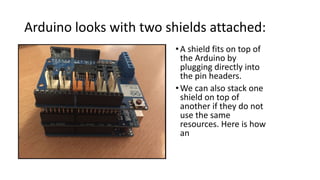
  • 8. Arduino looks with two shields attached: •A shield fits on top of the Arduino by plugging directly into the pin headers. •We can also stack one shield on top of another if they do not use the same resources. Here is how an
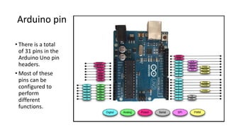
  • 9. Arduino pin • There is a total of 31 pins in the Arduino Uno pin headers. • Most of these pins can be configured to perform different functions.
  • 10. Digital pins •Used the most when connecting external sensors. •These pins can be configured for either input or output. •These pins default to an input state •The digital pins will have one of two values: HIGH (1), which is 5V, or LOW (0), which is 0V.
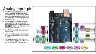
  • 11. Analog input pins • The Arduino Uno contains a built-in Analog-To-Digital (ADC) converter with six channels, which gives us six analog input pins. The ADC converts an analog signal into a digital value. • While the digital pins have two values, either high or low, the analog input pins have values from 0 to 1023 relative to the reference value of the Arduino. • The Arduino Uno has a reference value of 5V. • Used to read analog sensors such as rangefinders and temperature sensors. • The six analog pins can also be configured as digital pins if we run out of digital pins in our project.
  • 12. PWM pins • Where the analog input pins are designed to read analog sensors (input), the PWM pins are designed for output. PWM is a technique for obtaining analog results with digital output. • Since a digital output can be either on or off, to obtain the analog output the digital output is switch between HIGH and LOW rapidly. • The percentage of the time that the signal is high is called the duty cycle.
  • 13. Duty cycle • We have the ability to set the frequency of how fast the signal can switch between HIGH and LOW. • This frequency is measured in Hertz and sets how many times the signal can switch per second. • For example, if we set the frequency to 500 Hz, that would mean that the signal could switch 500 times a second. • This will be come clearer as we use the pins.
  • 14. Power pins • VIN: This pin is used when we power the Arduino board using an external power supply. • GND: These are the ground pins. • 5V: This is 5V out and is used to power most sensors. • 3.3V: This is 3.3V out and can be used to power sensors that are compatible with 3.3V. • Reset: This pin can be used to reset the Arduino board by an external source. • ioref: This is the reference voltage for the board. For the Arduino, this will be 5V.
  • 15. Serial pins • Used for serial communication. • The RX (digital pin 0) is used to receive. • TX (digital pin 1) is used to transmit. • Serial communications work on binary (1’s and 0’s). • Provided for legacy reasons primarily.
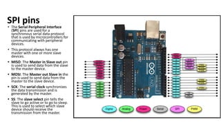
  • 16. SPI pins • The Serial Peripheral Interface (SPI) pins are used for a synchronous serial data protocol that is used by microcontrollers for communicating with peripheral devices. • This protocol always has one master with one or more slave devices. • MISO: The Master in Slave out pin is used to send data from the slave to the master device. • MOSI: The Master out Slave in the pin is used to send data from the master to the slave device. • SCK: The serial clock synchronizes the data transmission and is generated by the master. • SS: The slave select pin tells the slave to go active or to go to sleep. This is used to select which slave device should receive the transmission from the master.
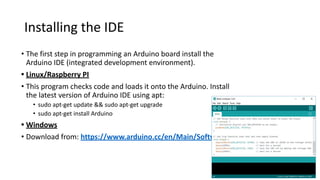
  • 17. Installing the IDE • The first step in programming an Arduino board install the Arduino IDE (integrated development environment). • Linux/Raspberry PI • This program checks code and loads it onto the Arduino. Install the latest version of Arduino IDE using apt: • sudo apt-get update && sudo apt-get upgrade • sudo apt-get install Arduino • Windows • Download from: https://www.arduino.cc/en/Main/Software
  • 18. Programming in for Arduino • The Arduino programming language is based on a very simple hardware programming language called processing, which is similar to the C language. • You create sketches which contain your code • After the sketch is written in the Arduino IDE, it should be uploaded on the Arduino board for execution. void setup( ) { statements; } void loop( ) { statement; } The setup function is the first to execute when the program is executed, and this function is called only once. Used to initialize the pin modes and start serial communication. This function has to be included even if there are no statements to execute. The execution block runs after setup and hosts statements like reading inputs, triggering outputs, checking conditions etc.. As the name suggests, the loop( ) function executes the set of statements (enclosed in curly braces) repeatedly. Basic code structure
  • 19. Example program int led = 9; // The digital pin to which the LED is connected int brightness = 0; // Brightness of LED is initially set to 0 int fade = 5; // By how many points the LED should fade void setup() { pinMode(led, OUTPUT); //pin 10 is set as output pin } void loop() // The loop function runs again and again { analogWrite(led, brightness); // set the brightness of LED brightness = brightness + fade; //Increase the brightness of LED by 5 points if (brightness <= 0 || brightness >= 255) // check the level of brightness { fade = -fade; } delay(30); // Wait for 30 milliseconds } LED fade-in and fade-out