SlideShare a Scribd company logo
GITS INNOVATION CELL
Object 1 :- LED glow by Arduino
GITS INNOVATION CELL
Object 2 :- Traffic light control by Arduino.
GITS INNOVATION CELL
Object 3 :- 7 segment Display control on Arduino.
GITS INNOVATION CELL
// C++ code
//
void setup()
{
pinMode(2, OUTPUT);
pinMode(3, OUTPUT);
pinMode(4, OUTPUT);
pinMode(5, OUTPUT);
pinMode(6, OUTPUT);
pinMode(7, OUTPUT);
pinMode(8, OUTPUT);
}
void loop()
{
digitalWrite(2, HIGH);
digitalWrite(3, HIGH);
digitalWrite(4, HIGH);
digitalWrite(5, LOW);
digitalWrite(6, HIGH);
digitalWrite(7, HIGH);
digitalWrite(8, HIGH);
delay(1000); // Wait for 1000 millisecond(s)
digitalWrite(2, HIGH);
digitalWrite(3, LOW);
digitalWrite(4, LOW);
digitalWrite(5, LOW);
GITS INNOVATION CELL
digitalWrite(6, LOW);
digitalWrite(7, LOW);
digitalWrite(8, HIGH);
delay(1000); // Wait for 1000 millisecond(s)
digitalWrite(2, HIGH);
digitalWrite(3, HIGH);
digitalWrite(4, LOW);
digitalWrite(5, HIGH);
digitalWrite(6, HIGH);
digitalWrite(7, HIGH);
digitalWrite(8, LOW);
delay(1000); // Wait for 1000 millisecond(s)
digitalWrite(2, HIGH);
digitalWrite(3, HIGH);
digitalWrite(4, LOW);
digitalWrite(5, HIGH);
digitalWrite(6, LOW);
digitalWrite(7, HIGH);
digitalWrite(8, HIGH);
delay(1000); // Wait for 1000 millisecond(s)
}
GITS INNOVATION CELL
Object 4 :- Forward and Reverse motion control of Servomotor by Arduino.
GITS INNOVATION CELL
#include <Servo.h>
Servo myservo; // create servo object to control a servo
// twelve servo objects can be created on most boards
int pos = 0; // variable to store the servo position
void setup() {
myservo.attach(9); // attaches the servo on pin 9 to the servo object
}
void loop() {
for (pos = 0; pos <= 180; pos += 1) { // goes from 0 degrees to 180 degrees
// in steps of 1 degree
myservo.write(pos); // tell servo to go to position in variable 'pos'
delay(15); // waits 15 ms for the servo to reach the position
}
for (pos = 180; pos >= 0; pos -= 1) { // goes from 180 degrees to 0 degrees
myservo.write(pos); // tell servo to go to position in variable 'pos'
delay(15); // waits 15 ms for the servo to reach the position
}
}
GITS INNOVATION CELL
Object 5 :- Speed control of Servomotor using Arduino
#include <Servo.h>
Servo myservo; // create servo object to control a servo
int potpin = A0; // analog pin used to connect the potentiometer
int val; // variable to read the value from the analog pin
void setup() {
myservo.attach(9); // attaches the servo on pin 9 to the servo object
}
void loop() {
val = analogRead(potpin); // reads the value of the potentiometer (value between 0 and 1023)
val = map(val, 0, 1023, 0, 180); // scale it for use with the servo (value between 0 and 180)
myservo.write(val); // sets the servo position according to the scaled value
delay(15); // waits for the servo to get there
}
GITS INNOVATION CELL
Object 6 :- DC Motor rotation control by Arduino.
GITS INNOVATION CELL
Object 7 :- Distance tracking by ultrsonic sensor by arduino.
GITS INNOVATION CELL
const int trig = 11;
const int echo = 12;
const int LED1 = 3;
const int LED2 = 4;
const int LED3 = 5;
int duration = 0;
int distance = 0;
void setup()
{
pinMode(trig , OUTPUT);
pinMode(echo , INPUT);
pinMode(LED1 , OUTPUT);
pinMode(LED2 , OUTPUT);
pinMode(LED3 , OUTPUT);
Serial.begin(9600);
}
void loop()
{
digitalWrite(trig , HIGH);
delayMicroseconds(1000);
digitalWrite(trig , LOW);
duration = pulseIn(echo , HIGH);
distance = (duration/2) / 28.5 ;
Serial.println(distance);
if ( distance <= 5 )
{
digitalWrite(LED1, HIGH);
}
else
{
digitalWrite(LED1, LOW);
}
if ( distance <= 15 )
{
digitalWrite(LED2, HIGH);
}
else
{
digitalWrite(LED2, LOW);
}
if ( distance <= 25 )
{
digitalWrite(LED3, HIGH);
}
else
GITS INNOVATION CELL
{
digitalWrite(LED3, LOW);
}
}
GITS INNOVATION CELL
Object 8 :- Controling LED using serial monitor
The serial monitor is the 'tether' between the computer and your Arduino - it lets you send and
receive text messages, handy for debugging and also controlling the Arduino from a keyboard! For
example, you will be able to send commands from your computer to turn on LEDs.
const int redPin = 8;
const int greenPin = 9;
const int bluePin = 10;
void setup() {
pinMode(redPin, OUTPUT);
pinMode(greenPin, OUTPUT);
pinMode(bluePin, OUTPUT);
Serial.begin(9600);
Serial.println("type R - RED ON, G - GREEN ON, B - BLUE ON, O - ALL is ON, F - ALL is OFF ");
Serial.print("choose the letter: ");
}
void loop() {
if (Serial.available() > 0) {
char comdata = char(Serial.read());
if (comdata == 'R') {
Serial.println("Red LED is ON");
digitalWrite(redPin, HIGH);
}
else if (comdata == 'G' ) {
Serial.println("Green LED is ON");
digitalWrite(greenPin, HIGH);
GITS INNOVATION CELL
}
else if (comdata == 'B') {
Serial.println("Blue LED is ON");
digitalWrite(bluePin, HIGH);
}
else if (comdata == 'O') {
Serial.println("all LED is turn ON");
digitalWrite(redPin, HIGH);
digitalWrite(greenPin, HIGH);
digitalWrite(bluePin, HIGH);
}
else if (comdata == 'F') {
Serial.println("all LED is turn OFF");
digitalWrite(redPin, LOW);
digitalWrite(greenPin, LOW);
digitalWrite(bluePin, LOW);
}
}
}
ONE LED
int led = 2;
int entry = 0;
void setup() {
pinMode(led, OUTPUT);
Serial.begin(9600);
}
void loop() {
if (Serial.available() > 0) {
entry = Serial.read();
if (entry == '1') {
digitalWrite(led, HIGH);
}
else if (entry == '0') {
digitalWrite(led, LOW);
}
else {
Serial.println("invalid input");
}
}
}
GITS INNOVATION CELL
Object 9:- LED ON /OFF USING SWITCH
#define LED_PIN 6
#define BUTTON_PIN 7
byte lastButtonState;
byte ledState = LOW;
unsigned long lastTimeButtonStateChanged = millis();
unsigned long debounceDuration= 50; // millis
void setup() {
pinMode(LED_PIN, OUTPUT);
pinMode(BUTTON_PIN, INPUT);
lastButtonState = digitalRead(BUTTON_PIN);
}
void loop() {
if (millis() - lastTimeButtonStateChanged >= debounceDuration) {
byte buttonState = digitalRead(BUTTON_PIN);
if (buttonState = lastButtonState){
lastTimeButtonStateChanged = millis();
lastButtonState = buttonState;
if (buttonState == LOW) { // released
if (ledState == HIGH) {
ledState = LOW;
}
else{
ledState = HIGH;
}
digitalWrite(LED_PIN, ledState);
}
}
}
}
GITS INNOVATION CELL
Object 10:- Distance Measurement using Ultrasonic sensor on LCD (16*2)
#include <LiquidCrystal.h>
LiquidCrystal lcd(2, 3, 4, 5, 6, 7);
#define echoPin 8 //echo pin
#define trigPin 9 //Trigger pin
#define led1 A0 //red led 1
#define led2 A1 //red led 2
#define led3 A2 //yellow led 3
#define led4 A3 //yellow led 4
#define led5 A4 //green led 5
#define led6 A5 //green led 6
float time;
float distance_cm;
float distance_in;
void setup(){
Serial.begin(9600);
pinMode(trigPin, OUTPUT);
pinMode(echoPin, INPUT);
pinMode(led1, OUTPUT);
pinMode(led2, OUTPUT);
pinMode(led3, OUTPUT);
pinMode(led4, OUTPUT);
pinMode(led5, OUTPUT);
pinMode(led6, OUTPUT);
lcd.begin(16, 2);
lcd.setCursor(0,0);
GITS INNOVATION CELL
lcd.print(" Hello ");
lcd.setCursor(0,1);
lcd.print("NAME");
delay(1000);
lcd.clear();
}
void loop(){
digitalWrite(trigPin, LOW); //PULSE ___|---|___
delayMicroseconds(2);
digitalWrite(trigPin, HIGH);
delayMicroseconds(10);
time = pulseIn(echoPin, HIGH);
distance_cm = (time/2) / 29.1; // distance for centimeter
distance_in = (time/2) / 73.914; // distance for inch
lcd.setCursor(0, 0);
lcd.print(" Distance ");
lcd.setCursor(0, 1);
lcd.print(distance_cm,1);
lcd.print("cm ");
lcd.setCursor(9, 1);
lcd.print(distance_in);
lcd.print("in ");
Serial.print("cm= ");
Serial.print(distance_cm);
Serial.print(" inch= ");
Serial.println(distance_in);
if(distance_cm<60){digitalWrite(led6, HIGH);}
else{digitalWrite(led6, LOW);}
if(distance_cm<50){digitalWrite(led5, HIGH);}
else{digitalWrite(led5, LOW);}
if(distance_cm<40){digitalWrite(led4, HIGH);}
else{digitalWrite(led4, LOW);}
if(distance_cm<30){digitalWrite(led3, HIGH);}
else{digitalWrite(led3, LOW);}
if(distance_cm<20){digitalWrite(led2, HIGH);}
else{digitalWrite(led2, LOW);}
if(distance_cm<10){digitalWrite(led1, HIGH);}
else{digitalWrite(led1, LOW);}
delay(200);
}
GITS INNOVATION CELL
Object 11 :- Servo with serial monitor
#include <Servo.h>
Servo servo_1; // servo controller (multiple can exist)
int servo_pin = 9; // PWM pin for servo control
int pos = 0; // servo starting position
void setup() {
servo_1.attach(servo_pin); // start servo control
Serial.begin(9600); // start serial monitor
servo_1.write(pos); // move servo to 0 degrees
Serial.println("Positioned at 0 Degrees");
Serial.println("Input Desired Angle and Press Enter");
}
void loop() {
while (Serial.available()){
String in_char = Serial.readStringUntil('n'); // read until the newline
Serial.print("Moving to: ");
Serial.print(in_char);
Serial.println(" Degrees");
servo_1.write(in_char.toInt()); // convert angle and write servo
delay(in_char.toFloat()*(10.0/6.0)); // delay for maximum speed
}
}
GITS INNOVATION CELL
Why it is called 16x2 ? Because you can write 16 characters or numbers in column wise and 2
in row wise. This display have total of 16 pins. Here I only use 12 pins. Here we use the pins
except D0, D1, D2, D3. Because here I interface the LCD in 4 bit mode.
The use of pins listed below
GND(VSS)
Connect the ground pin of the power supply to this pin. VCC
Connect this pin to 5v Contrast
(VEE)
This pin is used to adjust the contrast of Display. Connect a potentiometer (POT) to this pin.
Rotate the knob of the POT to adjust the contrast.
RS
RS pin means Register select pin. Selects command register when the pin is LOW. And selects
data register when this pin is HIGH.
RW
It represent the Read Write pin. When this pin is LOW, the MCU write to register. And when
the pin is HIGH, MCU read from the register. Here we want to write. It connect it permanently to
GND.
EN (E)
EN pin means the Enable pin. Send data to data pins when a HIGH to LOW pulse is given.
D0-D7 (DB0-DB7)
GITS INNOVATION CELL
These are 8 data pins. Here I interface this LCD with Arduino is in 4 bit mode. So we need only D4
to D7.
Backlight(+)
This is the anode pin of the backlight of the display Backlight(-)
This is the cathode pin of the backlight of the display Lets start!!!!!!!
First I am going to create a sketch for Arduino
Connections of LCD
GITS INNOVATION CELL
* LCD RS pin to digital pin 12
* LCD Enable pin to digital pin 11
* LCD D4 pin to digital pin 5
* LCD D5 pin to digital pin 4
* LCD D6 pin to digital pin 3
* LCD D7 pin to digital pin 2
* LCD R/W pin to ground
* LCD VSS pin to ground
* LCD VCC pin to 5V
* 10K POT:
* ends to +5V and ground
* wiper to LCD VO pin (pin 3)
GITS INNOVATION CELL
Object 12:- LCD NAME
// include the library code:
#include <LiquidCrystal.h>
// initialize the library by associating any needed LCD interface pin
// with the arduino pin number it is connected to
const int rs = 12, en = 11, d4 = 5, d5 = 4, d6 = 3, d7 = 2;
LiquidCrystal lcd(rs, en, d4, d5, d6, d7);
; // set the LCD address to 0x27 for a 16 chars and 2 line display
void setup()
{
lcd.begin(16, 2);
}
void loop()
{
lcd.setCursor(0,1);
lcd.print("name ");
lcd.setCursor(0,0);
lcd.print("name");
delay(1000);
lcd.clear();
lcd.setCursor(0,1);
lcd.print("name ");
lcd.setCursor(0,0);
lcd.print("name");
delay(1000);
lcd.clear();
lcd.setCursor(0,1);
GITS INNOVATION CELL
lcd.print(" name ");
lcd.setCursor(0,0);
lcd.print("name");
delay(1000);
lcd.clear();
}
GITS INNOVATION CELL
Object 13 :- LCD (16*2 ) print when button is pressed
#include <LiquidCrystal.h>
#define button A0
int i=0;
int bs=0;
int count=0;
int lastbs=0;
LiquidCrystal lcd(12, 11, 5, 4, 3, 2);
void setup() {
Serial.begin(9600);
pinMode(button, INPUT);
lcd.begin(16, 2);
delay(1000);
}
void loop() {
bs = analogRead(button);
delay(100);
Serial.println("buttonstate:=");
Serial.println(bs);
delay(50);
if (bs==lastbs)
{
count++;
Serial.println("count:::");
Serial.println(count);
if(count==5)
{
lcd.setCursor(0,1);
lcd.print(" MATCHED");
delay(1000);
count=0;
}
else{
lcd.setCursor(0,1);
lcd.print("NO MATCH");
delay(1000);
}
}
lastbs=bs;
}
GITS INNOVATION CELL
Object 14 :- LCD(16*2) scrolling
#include <LiquidCrystal.h>
const int rs = 12, en =11, d4= 5, d5= 4, d6= 3, d7=2;
LiquidCrystal lcd(rs, en, d4, d5, d6, d7);
void setup() {
lcd.begin(16, 2);
lcd.print("Hello World!!");
delay(100);
}
void loop() {
for(int positioncounter=0; positioncounter<13; positioncounter++){
lcd.scrollDisplayLeft();
delay(1000);
}
for(int positioncounter=0; positioncounter<29; positioncounter++){
lcd.scrollDisplayRight();
delay(1000);
}
for(int positioncounter=0; positioncounter<16; positioncounter++){
lcd.scrollDisplayLeft();
delay(1000);
}
delay(1000);
}
GITS INNOVATION CELL
Object 15 :- OLED
#include <Wire.h>
#include <Adafruit_GFX.h>
#include <Adafruit_SSD1306.h>
#define SCREEN_WIDTH 128 // OLED display width, in pixels
#define SCREEN_HEIGHT 64 // OLED display height, in pixels
Adafruit_SSD1306 display(SCREEN_WIDTH, SCREEN_HEIGHT, &Wire, -1);
void setup() {
Serial.begin(9600);
if(!display.begin(SSD1306_SWITCHCAPVCC, 0x3C)) { // Address 0x3D for 128x64
Serial.println(F("SSD1306 allocation failed"));
for(;;);
}
display.display(); //Display logo
delay(1000);
display.clearDisplay();
Serial.println("HI");
}
void loop() {
display.clearDisplay();
oledDisplayHeader();
oledDisplay(3,5,28,45.7,"%");
// oledDisplay(2,70,16,tempC,"C");
// oledDisplay(2,70,44,tempF,"F");
}
void oledDisplayHeader(){
display.setTextSize(1);
display.setTextColor(WHITE);
display.setCursor(0, 0);
display.print("Humidity");
GITS INNOVATION CELL
display.setCursor(60, 0);
display.print("Temperature");
}
void oledDisplay(int size, int x,int y, float value, String unit){
int charLen=12;
int xo=x+charLen*3.2;
int xunit=x+charLen*3.6;
int xval = x;
display.setTextSize(size);
display.setTextColor(WHITE);
if (unit=="%"){
display.setCursor(x, y);
display.print(value,0);
display.print(unit);
} else {
if (value>99){
xval=x;
} else {
xval=x+charLen;
}
display.setCursor(xval, y);
display.print(value,0);
display.drawCircle(xo, y+2, 2, WHITE); // print degree symbols ( )
display.setCursor(xunit, y);
display.print(unit);
}
}
GITS INNOVATION CELL
Object 16 :- Relay switching with arduino
int relayPin1 = 2; //This is the Arduino Pin that will control Relay #1
int relayPin2 = 3; //This is the Arduino Pin that will control Relay #2
int relayPin3 = 4; //This is the Arduino Pin that will control Relay #3
int relayPin4 = 5; //This is the Arduino Pin that will control Relay #4
int relayPin;
void setup() {
// put your setup code here, to run once:
pinMode(relayPin1, OUTPUT);
pinMode(relayPin2, OUTPUT);
pinMode(relayPin3, OUTPUT);
pinMode(relayPin4, OUTPUT);
digitalWrite(relayPin1, LOW);
digitalWrite(relayPin2, LOW);
digitalWrite(relayPin3, LOW);
digitalWrite(relayPin4, LOW);
}
void loop() {
//put your main code here, to run repeatedly: 33
digitalWrite(relayPin1,HIGH );
delay(100);
digitalWrite(relayPin1, LOW);
delay(100);
digitalWrite(relayPin2, HIGH);
delay(100);
digitalWrite(relayPin2, LOW);
digitalWrite(relayPin1, HIGH);
delay(100);
digitalWrite(relayPin2, HIGH);
delay(100);
digitalWrite(relayPin3, HIGH);
delay(500);
digitalWrite(relayPin3, LOW);
delay(500);
digitalWrite(relayPin4, HIGH);
delay(250);
digitalWrite(relayPin4, LOW);
delay(250);
}
GITS INNOVATION CELL
Object 17 :- DHT : The DHT-11 Digital Temperature And Humidity Sensor is a basic, ultra low-
cost digital temperature and humidity sensor. It uses a capacitive humidity sensor and a
thermistor to measure the surrounding air and spits out a digital signal on the data pin (no analog
input pins needed)
#include <dht.h>
#define dataPin 5 // Defines pin number to which the sensor is connected
dht DHT; // Creats a DHT object
void setup()
{
Serial.begin(9600);
}
void loop()
{
//Uncomment whatever type you're using!
int readData = DHT.read22(dataPin); // DHT22/AM2302
//int readData = DHT.read11(dataPin); // DHT11
float t = DHT.temperature; // Gets the values of the temperature
float h = DHT.humidity; // Gets the values of the humidity
// Printing the results on the serial monitor
Serial.print("Temperature = ");
Serial.print(t);
Serial.print(" ");
Serial.print((char)176);//shows degrees character
Serial.print("C | ");
Serial.print((t * 9.0) / 5.0 + 32.0);//print the temperature in Fahrenheit
Serial.print(" ");
Serial.print((char)176);//shows degrees character
Serial.println("F ");
Serial.print("Humidity = ");
Serial.print(h);
Serial.println(" % ");
Serial.println("");
delay(2000); // Delays 2 secods
}
GITS INNOVATION CELL
Object 18 :- GPS NEO 6M
#include <TinyGPS++.h>
#include <SoftwareSerial.h>
int RXPin = 10;
int TXPin = 9;
int GPSBaud = 9600;
TinyGPSPlus gps;
SoftwareSerial gpsSerial(RXPin, TXPin);
void setup()
{
// Start the Arduino hardware serial port at 9600 baud
Serial.begin(9600);
// Start the software serial port at the GPS's default baud
gpsSerial.begin(GPSBaud);
}
void loop()
{
while (gpsSerial.available() > 0)
if (gps.encode(gpsSerial.read()))
displayInfo();
if (millis() > 5000 && gps.charsProcessed() < 10)
{
Serial.println("No GPS detected");
while(true);
}
}
void displayInfo()
{
if (gps.location.isValid())
{
Serial.print("Latitude: ");
Serial.println(gps.location.lat(), 6);
Serial.print("Longitude: ");
Serial.println(gps.location.lng(), 6);
Serial.print("Altitude: ");
Serial.println(gps.altitude.meters());
}
else
{
Serial.println("Location: Not Available");
}
GITS INNOVATION CELL
Serial.print("Date: ");
if (gps.date.isValid())
{
Serial.print(gps.date.month());
Serial.print("/");
Serial.print(gps.date.day());
Serial.print("/");
Serial.println(gps.date.year());
}
else
{
Serial.println("Not Available");
}
Serial.print("Time: ");
if (gps.time.isValid())
{
if (gps.time.hour() < 10) Serial.print(F("0"));
Serial.print(gps.time.hour());
Serial.print(":");
if (gps.time.minute() < 10) Serial.print(F("0"));
Serial.print(gps.time.minute());
Serial.print(":");
if (gps.time.second() < 10) Serial.print(F("0"));
Serial.print(gps.time.second());
Serial.print(".");
if (gps.time.centisecond() < 10) Serial.print(F("0"));
Serial.println(gps.time.centisecond());
}
else
{
Serial.println("Not Available");
}
Serial.println();
Serial.println();
delay(1000);
}
GITS INNOVATION CELL
Object 19 :- IR sensor :
A proximity sensor is a device that can detect or sense the approach or presence of nearby
objects and for this it does not need physical contact
Controlling one led with IR sensor
int IRSensor = 2; // connect ir sensor to arduino pin 2
int LED = 13; // connect Led to arduino pin 13
void setup(){
pinMode (IRSensor, INPUT); // sensor pin INPUT
pinMode (LED, OUTPUT); // Led pin OUTPUT
}
void loop(){
int statusSensor = digitalRead (IRSensor);
if (statusSensor == 1)
{
digitalWrite(LED, LOW); // LED LOW
}
else
{
digitalWrite(LED, HIGH); // LED High
}
}
Controlling two led with IR sensor
int IRSensor = 2; // connect ir sensor to arduino pin 2
int REDLED = 11 ; // connect red LED to arduino pin 11
int GREENLED = 10 ; // connect green LED to arduino pin 10
void setup(){
pinMode (IRSensor, INPUT); // sensor pin INPUT
pinMode (REDLED, OUTPUT); // Led pin OUTPUT
pinMode (GREENLED, OUTPUT); // Led pin OUTPUT
Serial.begin(9600);
}
void loop(){
int statusSensor = digitalRead (IRSensor);
if (statusSensor == 1) {
GITS INNOVATION CELL
Serial.print("IRSensor ");
Serial.println(statusSensor);
digitalWrite(GREENLED, HIGH); // Green LED is HIGH if IR sensor detect something
}
else
{
digitalWrite(REDLED, HIGH); // Red LED is HIGH if nothing is detected
}
}
GITS INNOVATION CELL
Object 20 :- PIR motion sensor : A passive infrared sensor (PIR sensor) is an
electronic sensor that measures infrared (IR) light radiating from objects in its
field of view. They are most often used in PIR-based motion detectors. PIR sensors
are commonly used in security alarms and automatic lighting applications.
PIR motion sensor with LED
int led = 13; // the pin that the LED is atteched to
int sensor = 2; // the pin that the sensor is atteched to
int state = LOW; // by default, no motion detected
int val = 0; // variable to store the sensor status (value)
void setup() {
pinMode(led, OUTPUT); // initalize LED as an output
pinMode(sensor, INPUT); // initialize sensor as an input
Serial.begin(9600); // initialize serial
}
void loop(){
val = digitalRead(sensor); // read sensor value
if (val == HIGH) { // check if the sensor is HIGH
digitalWrite(led, HIGH); // turn LED ON
delay(500); // delay 100 milliseconds
if (state == LOW) {
Serial.println("Motion detected!");
state = HIGH; // update variable state to HIGH
}
}
else {
digitalWrite(led, LOW); // turn LED OFF
delay(500); // delay 200 milliseconds
if (state == HIGH){
Serial.println("Motion stopped!");
state = LOW; // update variable state to LOW
}
}
}
GITS INNOVATION CELL
PIR motion sensor with buzzer
//the time we give the sensor to calibrate (10-60 secs according to the datasheet)
int calibrationTime = 30;
//the time when the sensor outputs a low impulse
long unsigned int lowIn;
//the amount of milliseconds the sensor has to be low
//before we assume all motion has stopped
long unsigned int pause = 5000;
boolean lockLow = true;
boolean takeLowTime;
int pirPin = 3; //the digital pin connected to the PIR sensor's output
int ledPin = 13;
/////////////////////////////
//SETUP
void setup(){
Serial.begin(9600);
pinMode(pirPin, INPUT);
pinMode(ledPin, OUTPUT);
digitalWrite(pirPin, LOW);
//give the sensor some time to calibrate
Serial.print("calibrating sensor ");
for(int i = 0; i < calibrationTime; i++){
Serial.print(".");
delay(1000);
}
Serial.println(" done");
Serial.println("SENSOR ACTIVE");
delay(50);
}
////////////////////////////
//LOOP
void loop(){
if(digitalRead(pirPin) == HIGH){
digitalWrite(ledPin, HIGH); //the led visualizes the sensors output pin state
if(lockLow){
//makes sure we wait for a transition to LOW before any further output is made:
lockLow = false;
Serial.println("---");
Serial.print("motion detected at ");
Serial.print(millis()/1000);
GITS INNOVATION CELL
Serial.println(" sec");
delay(50);
}
takeLowTime = true;
}
if(digitalRead(pirPin) == LOW){
digitalWrite(ledPin, LOW); //the led visualizes the sensors output pin state
if(takeLowTime){
lowIn = millis(); //save the time of the transition from high to LOW
takeLowTime = false; //make sure this is only done at the start of a LOW phase
}
//if the sensor is low for more than the given pause,
//we assume that no more motion is going to happen
if(!lockLow && millis() - lowIn > pause){
//makes sure this block of code is only executed again after
//a new motion sequence has been detected
lockLow = true;
Serial.print("motion ended at "); //output
Serial.print((millis() - pause)/1000);
Serial.println(" sec");
delay(50);
}
}
}
GITS INNOVATION CELL
Object 21:- GSM SIM 900A
SIM900A is an ultra compact and reliable wireless module. This is a complete GSM/GPRS
module in a SMT type and designed with a very powerful single-chip processor integrating
AMR926EJ-S core, allowing you to benefit from small dimensions and cost-effective solutions.
#include <SoftwareSerial.h>
SoftwareSerial mySerial(9,10);
void setup()
{
mySerial.begin(9600); // Setting the baud rate of GSM Module
Serial.begin(9600); // Setting the baud rate of Serial Monitor (Arduino)
delay(100);
}
void loop()
{
if (Serial.available()>0)
switch(Serial.read())
{
case 's':
SendMessage();
break;
case 'r':
RecieveMessage();
break;
}
if (mySerial.available()>0)
Serial.write(mySerial.read());
}
void SendMessage()
{
mySerial.println("AT+CMGF=1"); //Sets the GSM Module in Text Mode
delay(1000); // Delay of 1000 milli seconds or 1 second
mySerial.println("AT+CMGS="+919872436823"r"); // Replace x with mobile number
delay(1000);
mySerial.println("hi how are u doing?");// The SMS text you want to send
delay(100);
mySerial.println((char)26);// ASCII code of CTRL+Z
delay(1000);
}
void RecieveMessage()
{
mySerial.println("AT+CNMI=2,2,0,0,0"); // AT Command to receive a live SMS
GITS INNOVATION CELL
delay(1000);
}
GITS INNOVATION CELL
Object 22 :- Motor with l298 motor driver
int motor1pin1 = 2;
int motor1pin2 = 3;
int motor2pin1 = 4;
int motor2pin2 = 5;
void setup() {
// put your setup code here, to run once:
pinMode(motor1pin1, OUTPUT);
pinMode(motor1pin2, OUTPUT);
pinMode(motor2pin1, OUTPUT);
pinMode(motor2pin2, OUTPUT);
}
void loop() {
// put your main code here, to run repeatedly:
digitalWrite(motor1pin1, HIGH);
digitalWrite(motor1pin2, LOW);
digitalWrite(motor2pin1, HIGH);
digitalWrite(motor2pin2, LOW);
delay(1000);
digitalWrite(motor1pin1, LOW);
digitalWrite(motor1pin2, HIGH);
digitalWrite(motor2pin1, LOW);
digitalWrite(motor2pin2, HIGH);
delay(1000);
}
GITS INNOVATION CELL
Object 22 :- Bluethooth with led
Here's how to use HC-05 Bluetooth Module with Arduino. And build Android App using MIT App
Inventor to control devices connected over Bluetooth.
char Incoming_value = 0;
void setup()
{
Serial.begin(9600);
pinMode(13, OUTPUT);
}
void loop()
{
if(Serial.available() > 0)
{
Incoming_value = Serial.read();
Serial.print(Incoming_value);
Serial.print("n");
if(Incoming_value == '1')
digitalWrite(13, HIGH);
else if(Incoming_value == '0')
digitalWrite(13, LOW);
}
}
GITS INNOVATION CELL
Led control using voice command
String voice;
int RED = 2;
int GREEN = 3;
int BLUE = 4;
void RedOn(){
digitalWrite (RED, HIGH);
}
void RedOff(){
digitalWrite (RED, LOW);
}
void GreenOn(){
digitalWrite (GREEN, HIGH);
}
void GreenOff(){
digitalWrite (GREEN, LOW);
}
void BlueOn(){
digitalWrite (BLUE, HIGH);
}
void BlueOff(){
digitalWrite (BLUE, LOW);
}
void allon() {
digitalWrite (RED, HIGH);
digitalWrite (GREEN, HIGH);
digitalWrite (BLUE, HIGH);
}
void alloff() {
digitalWrite (RED, LOW);
digitalWrite (GREEN, LOW);
digitalWrite (BLUE, LOW);
}
void setup() {
Serial.begin(9600);
pinMode(RED, OUTPUT);
pinMode(GREEN, OUTPUT);
pinMode(BLUE, OUTPUT);
}
void loop() {
GITS INNOVATION CELL
while(Serial.available()) {
delay(10);
char c=Serial.read();
if(c=='#')
{break; }
voice += c;
}
if (voice.length() > 0) {
Serial.println(voice);
if (voice == "on" || voice == "all")
{
allon() ;
}
else if (voice == "off" || voice=="all off")
{
alloff() ;
}
else if(voice =="red" || voice =="red on"){
RedOn();
}
else if(voice =="red off"){
RedOff();
}
else if(voice =="green" || voice =="green on"){
GreenOn();
}
else if( voice =="green off" ){
GreenOff();
}
else if(voice =="blue" || voice =="blue on"){
BlueOn();
}
else if(voice =="blue off"){
BlueOff();
}
voice="";
}
}

More Related Content

Similar to Arduino uno basic Experiments for beginner (20)

PPTX
Computer networks unit III CHAPTER of frameworks
manforlover7
 
PPTX
Arduino cic3
Jeni Shah
 
PDF
4 IOT 18ISDE712 MODULE 4 IoT Physical Devices and End Point-Aurdino Uno.pdf
Jayanthi Kannan MK
 
PPTX
Temperature Sensor with LED matrix Display BY ►iRFAN QADOOS◄ 9
Irfan Qadoos
 
PDF
Getting Started With Raspberry Pi - UCSD 2013
Tom Paulus
 
PPTX
INTODUCTION OF IOT AND INTERFACING WITH ARDUINO UNO
vasankarponnapalli2
 
PPT
Physical prototyping lab2-analog_digital
Tony Olsson.
 
PPT
Physical prototyping lab2-analog_digital
Tony Olsson.
 
PPT
01 Intro to the Arduino and it's basics.ppt
pindi2197
 
PPTX
Arduino intro.pptx
SanthanaMari11
 
KEY
Scottish Ruby Conference 2010 Arduino, Ruby RAD
lostcaggy
 
PDF
Automatic room light controller with visible counter
Mafaz Ahmed
 
PDF
The IoT Academy IoT Training Arduino Part 3 programming
The IOT Academy
 
PDF
Arduino Workshop 2011.05.31
Shigeru Kobayashi
 
PDF
Starting with Arduino
MajdyShamasneh
 
PDF
Arduino based applications part 1
Jawaher Abdulwahab Fadhil
 
PPTX
Arduino . .
dryazhinians
 
PDF
Introduction to Arduino
Luki B. Subekti
 
DOC
Anup2
David Gyle
 
PPTX
Arduino.pptx
ArunKumar313658
 
Computer networks unit III CHAPTER of frameworks
manforlover7
 
Arduino cic3
Jeni Shah
 
4 IOT 18ISDE712 MODULE 4 IoT Physical Devices and End Point-Aurdino Uno.pdf
Jayanthi Kannan MK
 
Temperature Sensor with LED matrix Display BY ►iRFAN QADOOS◄ 9
Irfan Qadoos
 
Getting Started With Raspberry Pi - UCSD 2013
Tom Paulus
 
INTODUCTION OF IOT AND INTERFACING WITH ARDUINO UNO
vasankarponnapalli2
 
Physical prototyping lab2-analog_digital
Tony Olsson.
 
Physical prototyping lab2-analog_digital
Tony Olsson.
 
01 Intro to the Arduino and it's basics.ppt
pindi2197
 
Arduino intro.pptx
SanthanaMari11
 
Scottish Ruby Conference 2010 Arduino, Ruby RAD
lostcaggy
 
Automatic room light controller with visible counter
Mafaz Ahmed
 
The IoT Academy IoT Training Arduino Part 3 programming
The IOT Academy
 
Arduino Workshop 2011.05.31
Shigeru Kobayashi
 
Starting with Arduino
MajdyShamasneh
 
Arduino based applications part 1
Jawaher Abdulwahab Fadhil
 
Arduino . .
dryazhinians
 
Introduction to Arduino
Luki B. Subekti
 
Anup2
David Gyle
 
Arduino.pptx
ArunKumar313658
 

Recently uploaded (20)

PPTX
Solar Thermal Energy System Seminar.pptx
Gpc Purapuza
 
PDF
Zilliz Cloud Demo for performance and scale
Zilliz
 
PDF
Set Relation Function Practice session 24.05.2025.pdf
DrStephenStrange4
 
PPTX
Green Building & Energy Conservation ppt
Sagar Sarangi
 
PPTX
Evaluation and thermal analysis of shell and tube heat exchanger as per requi...
shahveer210504
 
PPTX
Worm gear strength and wear calculation as per standard VB Bhandari Databook.
shahveer210504
 
PPTX
原版一样(Acadia毕业证书)加拿大阿卡迪亚大学毕业证办理方法
Taqyea
 
PDF
MAD Unit - 1 Introduction of Android IT Department
JappanMavani
 
PPTX
GitOps_Without_K8s_Training_detailed git repository
DanialHabibi2
 
PPTX
Introduction to Neural Networks and Perceptron Learning Algorithm.pptx
Kayalvizhi A
 
PPTX
Depth First Search Algorithm in 🧠 DFS in Artificial Intelligence (AI)
rafeeqshaik212002
 
PPTX
Shinkawa Proposal to meet Vibration API670.pptx
AchmadBashori2
 
PPTX
Types of Bearing_Specifications_PPT.pptx
PranjulAgrahariAkash
 
PPTX
Hashing Introduction , hash functions and techniques
sailajam21
 
PPTX
Day2 B2 Best.pptx
helenjenefa1
 
PDF
Biomechanics of Gait: Engineering Solutions for Rehabilitation (www.kiu.ac.ug)
publication11
 
PDF
Basic_Concepts_in_Clinical_Biochemistry_2018كيمياء_عملي.pdf
AdelLoin
 
DOCX
CS-802 (A) BDH Lab manual IPS Academy Indore
thegodhimself05
 
PPTX
Mechanical Design of shell and tube heat exchangers as per ASME Sec VIII Divi...
shahveer210504
 
PDF
Unified_Cloud_Comm_Presentation anil singh ppt
anilsingh298751
 
Solar Thermal Energy System Seminar.pptx
Gpc Purapuza
 
Zilliz Cloud Demo for performance and scale
Zilliz
 
Set Relation Function Practice session 24.05.2025.pdf
DrStephenStrange4
 
Green Building & Energy Conservation ppt
Sagar Sarangi
 
Evaluation and thermal analysis of shell and tube heat exchanger as per requi...
shahveer210504
 
Worm gear strength and wear calculation as per standard VB Bhandari Databook.
shahveer210504
 
原版一样(Acadia毕业证书)加拿大阿卡迪亚大学毕业证办理方法
Taqyea
 
MAD Unit - 1 Introduction of Android IT Department
JappanMavani
 
GitOps_Without_K8s_Training_detailed git repository
DanialHabibi2
 
Introduction to Neural Networks and Perceptron Learning Algorithm.pptx
Kayalvizhi A
 
Depth First Search Algorithm in 🧠 DFS in Artificial Intelligence (AI)
rafeeqshaik212002
 
Shinkawa Proposal to meet Vibration API670.pptx
AchmadBashori2
 
Types of Bearing_Specifications_PPT.pptx
PranjulAgrahariAkash
 
Hashing Introduction , hash functions and techniques
sailajam21
 
Day2 B2 Best.pptx
helenjenefa1
 
Biomechanics of Gait: Engineering Solutions for Rehabilitation (www.kiu.ac.ug)
publication11
 
Basic_Concepts_in_Clinical_Biochemistry_2018كيمياء_عملي.pdf
AdelLoin
 
CS-802 (A) BDH Lab manual IPS Academy Indore
thegodhimself05
 
Mechanical Design of shell and tube heat exchangers as per ASME Sec VIII Divi...
shahveer210504
 
Unified_Cloud_Comm_Presentation anil singh ppt
anilsingh298751
 
Ad

Arduino uno basic Experiments for beginner

  • 1. GITS INNOVATION CELL Object 1 :- LED glow by Arduino
  • 2. GITS INNOVATION CELL Object 2 :- Traffic light control by Arduino.
  • 3. GITS INNOVATION CELL Object 3 :- 7 segment Display control on Arduino.
  • 5. GITS INNOVATION CELL // C++ code // void setup() { pinMode(2, OUTPUT); pinMode(3, OUTPUT); pinMode(4, OUTPUT); pinMode(5, OUTPUT); pinMode(6, OUTPUT); pinMode(7, OUTPUT); pinMode(8, OUTPUT); } void loop() { digitalWrite(2, HIGH); digitalWrite(3, HIGH); digitalWrite(4, HIGH); digitalWrite(5, LOW); digitalWrite(6, HIGH); digitalWrite(7, HIGH); digitalWrite(8, HIGH); delay(1000); // Wait for 1000 millisecond(s) digitalWrite(2, HIGH); digitalWrite(3, LOW); digitalWrite(4, LOW); digitalWrite(5, LOW);
  • 6. GITS INNOVATION CELL digitalWrite(6, LOW); digitalWrite(7, LOW); digitalWrite(8, HIGH); delay(1000); // Wait for 1000 millisecond(s) digitalWrite(2, HIGH); digitalWrite(3, HIGH); digitalWrite(4, LOW); digitalWrite(5, HIGH); digitalWrite(6, HIGH); digitalWrite(7, HIGH); digitalWrite(8, LOW); delay(1000); // Wait for 1000 millisecond(s) digitalWrite(2, HIGH); digitalWrite(3, HIGH); digitalWrite(4, LOW); digitalWrite(5, HIGH); digitalWrite(6, LOW); digitalWrite(7, HIGH); digitalWrite(8, HIGH); delay(1000); // Wait for 1000 millisecond(s) }
  • 7. GITS INNOVATION CELL Object 4 :- Forward and Reverse motion control of Servomotor by Arduino.
  • 8. GITS INNOVATION CELL #include <Servo.h> Servo myservo; // create servo object to control a servo // twelve servo objects can be created on most boards int pos = 0; // variable to store the servo position void setup() { myservo.attach(9); // attaches the servo on pin 9 to the servo object } void loop() { for (pos = 0; pos <= 180; pos += 1) { // goes from 0 degrees to 180 degrees // in steps of 1 degree myservo.write(pos); // tell servo to go to position in variable 'pos' delay(15); // waits 15 ms for the servo to reach the position } for (pos = 180; pos >= 0; pos -= 1) { // goes from 180 degrees to 0 degrees myservo.write(pos); // tell servo to go to position in variable 'pos' delay(15); // waits 15 ms for the servo to reach the position } }
  • 9. GITS INNOVATION CELL Object 5 :- Speed control of Servomotor using Arduino #include <Servo.h> Servo myservo; // create servo object to control a servo int potpin = A0; // analog pin used to connect the potentiometer int val; // variable to read the value from the analog pin void setup() { myservo.attach(9); // attaches the servo on pin 9 to the servo object } void loop() { val = analogRead(potpin); // reads the value of the potentiometer (value between 0 and 1023) val = map(val, 0, 1023, 0, 180); // scale it for use with the servo (value between 0 and 180) myservo.write(val); // sets the servo position according to the scaled value delay(15); // waits for the servo to get there }
  • 10. GITS INNOVATION CELL Object 6 :- DC Motor rotation control by Arduino.
  • 11. GITS INNOVATION CELL Object 7 :- Distance tracking by ultrsonic sensor by arduino.
  • 12. GITS INNOVATION CELL const int trig = 11; const int echo = 12; const int LED1 = 3; const int LED2 = 4; const int LED3 = 5; int duration = 0; int distance = 0; void setup() { pinMode(trig , OUTPUT); pinMode(echo , INPUT); pinMode(LED1 , OUTPUT); pinMode(LED2 , OUTPUT); pinMode(LED3 , OUTPUT); Serial.begin(9600); } void loop() { digitalWrite(trig , HIGH); delayMicroseconds(1000); digitalWrite(trig , LOW); duration = pulseIn(echo , HIGH); distance = (duration/2) / 28.5 ; Serial.println(distance); if ( distance <= 5 ) { digitalWrite(LED1, HIGH); } else { digitalWrite(LED1, LOW); } if ( distance <= 15 ) { digitalWrite(LED2, HIGH); } else { digitalWrite(LED2, LOW); } if ( distance <= 25 ) { digitalWrite(LED3, HIGH); } else
  • 14. GITS INNOVATION CELL Object 8 :- Controling LED using serial monitor The serial monitor is the 'tether' between the computer and your Arduino - it lets you send and receive text messages, handy for debugging and also controlling the Arduino from a keyboard! For example, you will be able to send commands from your computer to turn on LEDs. const int redPin = 8; const int greenPin = 9; const int bluePin = 10; void setup() { pinMode(redPin, OUTPUT); pinMode(greenPin, OUTPUT); pinMode(bluePin, OUTPUT); Serial.begin(9600); Serial.println("type R - RED ON, G - GREEN ON, B - BLUE ON, O - ALL is ON, F - ALL is OFF "); Serial.print("choose the letter: "); } void loop() { if (Serial.available() > 0) { char comdata = char(Serial.read()); if (comdata == 'R') { Serial.println("Red LED is ON"); digitalWrite(redPin, HIGH); } else if (comdata == 'G' ) { Serial.println("Green LED is ON"); digitalWrite(greenPin, HIGH);
  • 15. GITS INNOVATION CELL } else if (comdata == 'B') { Serial.println("Blue LED is ON"); digitalWrite(bluePin, HIGH); } else if (comdata == 'O') { Serial.println("all LED is turn ON"); digitalWrite(redPin, HIGH); digitalWrite(greenPin, HIGH); digitalWrite(bluePin, HIGH); } else if (comdata == 'F') { Serial.println("all LED is turn OFF"); digitalWrite(redPin, LOW); digitalWrite(greenPin, LOW); digitalWrite(bluePin, LOW); } } } ONE LED int led = 2; int entry = 0; void setup() { pinMode(led, OUTPUT); Serial.begin(9600); } void loop() { if (Serial.available() > 0) { entry = Serial.read(); if (entry == '1') { digitalWrite(led, HIGH); } else if (entry == '0') { digitalWrite(led, LOW); } else { Serial.println("invalid input"); } } }
  • 16. GITS INNOVATION CELL Object 9:- LED ON /OFF USING SWITCH #define LED_PIN 6 #define BUTTON_PIN 7 byte lastButtonState; byte ledState = LOW; unsigned long lastTimeButtonStateChanged = millis(); unsigned long debounceDuration= 50; // millis void setup() { pinMode(LED_PIN, OUTPUT); pinMode(BUTTON_PIN, INPUT); lastButtonState = digitalRead(BUTTON_PIN); } void loop() { if (millis() - lastTimeButtonStateChanged >= debounceDuration) { byte buttonState = digitalRead(BUTTON_PIN); if (buttonState = lastButtonState){ lastTimeButtonStateChanged = millis(); lastButtonState = buttonState; if (buttonState == LOW) { // released if (ledState == HIGH) { ledState = LOW; } else{ ledState = HIGH; } digitalWrite(LED_PIN, ledState); } } } }
  • 17. GITS INNOVATION CELL Object 10:- Distance Measurement using Ultrasonic sensor on LCD (16*2) #include <LiquidCrystal.h> LiquidCrystal lcd(2, 3, 4, 5, 6, 7); #define echoPin 8 //echo pin #define trigPin 9 //Trigger pin #define led1 A0 //red led 1 #define led2 A1 //red led 2 #define led3 A2 //yellow led 3 #define led4 A3 //yellow led 4 #define led5 A4 //green led 5 #define led6 A5 //green led 6 float time; float distance_cm; float distance_in; void setup(){ Serial.begin(9600); pinMode(trigPin, OUTPUT); pinMode(echoPin, INPUT); pinMode(led1, OUTPUT); pinMode(led2, OUTPUT); pinMode(led3, OUTPUT); pinMode(led4, OUTPUT); pinMode(led5, OUTPUT); pinMode(led6, OUTPUT); lcd.begin(16, 2); lcd.setCursor(0,0);
  • 18. GITS INNOVATION CELL lcd.print(" Hello "); lcd.setCursor(0,1); lcd.print("NAME"); delay(1000); lcd.clear(); } void loop(){ digitalWrite(trigPin, LOW); //PULSE ___|---|___ delayMicroseconds(2); digitalWrite(trigPin, HIGH); delayMicroseconds(10); time = pulseIn(echoPin, HIGH); distance_cm = (time/2) / 29.1; // distance for centimeter distance_in = (time/2) / 73.914; // distance for inch lcd.setCursor(0, 0); lcd.print(" Distance "); lcd.setCursor(0, 1); lcd.print(distance_cm,1); lcd.print("cm "); lcd.setCursor(9, 1); lcd.print(distance_in); lcd.print("in "); Serial.print("cm= "); Serial.print(distance_cm); Serial.print(" inch= "); Serial.println(distance_in); if(distance_cm<60){digitalWrite(led6, HIGH);} else{digitalWrite(led6, LOW);} if(distance_cm<50){digitalWrite(led5, HIGH);} else{digitalWrite(led5, LOW);} if(distance_cm<40){digitalWrite(led4, HIGH);} else{digitalWrite(led4, LOW);} if(distance_cm<30){digitalWrite(led3, HIGH);} else{digitalWrite(led3, LOW);} if(distance_cm<20){digitalWrite(led2, HIGH);} else{digitalWrite(led2, LOW);} if(distance_cm<10){digitalWrite(led1, HIGH);} else{digitalWrite(led1, LOW);} delay(200); }
  • 19. GITS INNOVATION CELL Object 11 :- Servo with serial monitor #include <Servo.h> Servo servo_1; // servo controller (multiple can exist) int servo_pin = 9; // PWM pin for servo control int pos = 0; // servo starting position void setup() { servo_1.attach(servo_pin); // start servo control Serial.begin(9600); // start serial monitor servo_1.write(pos); // move servo to 0 degrees Serial.println("Positioned at 0 Degrees"); Serial.println("Input Desired Angle and Press Enter"); } void loop() { while (Serial.available()){ String in_char = Serial.readStringUntil('n'); // read until the newline Serial.print("Moving to: "); Serial.print(in_char); Serial.println(" Degrees"); servo_1.write(in_char.toInt()); // convert angle and write servo delay(in_char.toFloat()*(10.0/6.0)); // delay for maximum speed } }
  • 20. GITS INNOVATION CELL Why it is called 16x2 ? Because you can write 16 characters or numbers in column wise and 2 in row wise. This display have total of 16 pins. Here I only use 12 pins. Here we use the pins except D0, D1, D2, D3. Because here I interface the LCD in 4 bit mode. The use of pins listed below GND(VSS) Connect the ground pin of the power supply to this pin. VCC Connect this pin to 5v Contrast (VEE) This pin is used to adjust the contrast of Display. Connect a potentiometer (POT) to this pin. Rotate the knob of the POT to adjust the contrast. RS RS pin means Register select pin. Selects command register when the pin is LOW. And selects data register when this pin is HIGH. RW It represent the Read Write pin. When this pin is LOW, the MCU write to register. And when the pin is HIGH, MCU read from the register. Here we want to write. It connect it permanently to GND. EN (E) EN pin means the Enable pin. Send data to data pins when a HIGH to LOW pulse is given. D0-D7 (DB0-DB7)
  • 21. GITS INNOVATION CELL These are 8 data pins. Here I interface this LCD with Arduino is in 4 bit mode. So we need only D4 to D7. Backlight(+) This is the anode pin of the backlight of the display Backlight(-) This is the cathode pin of the backlight of the display Lets start!!!!!!! First I am going to create a sketch for Arduino Connections of LCD
  • 22. GITS INNOVATION CELL * LCD RS pin to digital pin 12 * LCD Enable pin to digital pin 11 * LCD D4 pin to digital pin 5 * LCD D5 pin to digital pin 4 * LCD D6 pin to digital pin 3 * LCD D7 pin to digital pin 2 * LCD R/W pin to ground * LCD VSS pin to ground * LCD VCC pin to 5V * 10K POT: * ends to +5V and ground * wiper to LCD VO pin (pin 3)
  • 23. GITS INNOVATION CELL Object 12:- LCD NAME // include the library code: #include <LiquidCrystal.h> // initialize the library by associating any needed LCD interface pin // with the arduino pin number it is connected to const int rs = 12, en = 11, d4 = 5, d5 = 4, d6 = 3, d7 = 2; LiquidCrystal lcd(rs, en, d4, d5, d6, d7); ; // set the LCD address to 0x27 for a 16 chars and 2 line display void setup() { lcd.begin(16, 2); } void loop() { lcd.setCursor(0,1); lcd.print("name "); lcd.setCursor(0,0); lcd.print("name"); delay(1000); lcd.clear(); lcd.setCursor(0,1); lcd.print("name "); lcd.setCursor(0,0); lcd.print("name"); delay(1000); lcd.clear(); lcd.setCursor(0,1);
  • 24. GITS INNOVATION CELL lcd.print(" name "); lcd.setCursor(0,0); lcd.print("name"); delay(1000); lcd.clear(); }
  • 25. GITS INNOVATION CELL Object 13 :- LCD (16*2 ) print when button is pressed #include <LiquidCrystal.h> #define button A0 int i=0; int bs=0; int count=0; int lastbs=0; LiquidCrystal lcd(12, 11, 5, 4, 3, 2); void setup() { Serial.begin(9600); pinMode(button, INPUT); lcd.begin(16, 2); delay(1000); } void loop() { bs = analogRead(button); delay(100); Serial.println("buttonstate:="); Serial.println(bs); delay(50); if (bs==lastbs) { count++; Serial.println("count:::"); Serial.println(count); if(count==5) { lcd.setCursor(0,1); lcd.print(" MATCHED"); delay(1000); count=0; } else{ lcd.setCursor(0,1); lcd.print("NO MATCH"); delay(1000); } } lastbs=bs; }
  • 26. GITS INNOVATION CELL Object 14 :- LCD(16*2) scrolling #include <LiquidCrystal.h> const int rs = 12, en =11, d4= 5, d5= 4, d6= 3, d7=2; LiquidCrystal lcd(rs, en, d4, d5, d6, d7); void setup() { lcd.begin(16, 2); lcd.print("Hello World!!"); delay(100); } void loop() { for(int positioncounter=0; positioncounter<13; positioncounter++){ lcd.scrollDisplayLeft(); delay(1000); } for(int positioncounter=0; positioncounter<29; positioncounter++){ lcd.scrollDisplayRight(); delay(1000); } for(int positioncounter=0; positioncounter<16; positioncounter++){ lcd.scrollDisplayLeft(); delay(1000); } delay(1000); }
  • 27. GITS INNOVATION CELL Object 15 :- OLED #include <Wire.h> #include <Adafruit_GFX.h> #include <Adafruit_SSD1306.h> #define SCREEN_WIDTH 128 // OLED display width, in pixels #define SCREEN_HEIGHT 64 // OLED display height, in pixels Adafruit_SSD1306 display(SCREEN_WIDTH, SCREEN_HEIGHT, &Wire, -1); void setup() { Serial.begin(9600); if(!display.begin(SSD1306_SWITCHCAPVCC, 0x3C)) { // Address 0x3D for 128x64 Serial.println(F("SSD1306 allocation failed")); for(;;); } display.display(); //Display logo delay(1000); display.clearDisplay(); Serial.println("HI"); } void loop() { display.clearDisplay(); oledDisplayHeader(); oledDisplay(3,5,28,45.7,"%"); // oledDisplay(2,70,16,tempC,"C"); // oledDisplay(2,70,44,tempF,"F"); } void oledDisplayHeader(){ display.setTextSize(1); display.setTextColor(WHITE); display.setCursor(0, 0); display.print("Humidity");
  • 28. GITS INNOVATION CELL display.setCursor(60, 0); display.print("Temperature"); } void oledDisplay(int size, int x,int y, float value, String unit){ int charLen=12; int xo=x+charLen*3.2; int xunit=x+charLen*3.6; int xval = x; display.setTextSize(size); display.setTextColor(WHITE); if (unit=="%"){ display.setCursor(x, y); display.print(value,0); display.print(unit); } else { if (value>99){ xval=x; } else { xval=x+charLen; } display.setCursor(xval, y); display.print(value,0); display.drawCircle(xo, y+2, 2, WHITE); // print degree symbols ( ) display.setCursor(xunit, y); display.print(unit); } }
  • 29. GITS INNOVATION CELL Object 16 :- Relay switching with arduino int relayPin1 = 2; //This is the Arduino Pin that will control Relay #1 int relayPin2 = 3; //This is the Arduino Pin that will control Relay #2 int relayPin3 = 4; //This is the Arduino Pin that will control Relay #3 int relayPin4 = 5; //This is the Arduino Pin that will control Relay #4 int relayPin; void setup() { // put your setup code here, to run once: pinMode(relayPin1, OUTPUT); pinMode(relayPin2, OUTPUT); pinMode(relayPin3, OUTPUT); pinMode(relayPin4, OUTPUT); digitalWrite(relayPin1, LOW); digitalWrite(relayPin2, LOW); digitalWrite(relayPin3, LOW); digitalWrite(relayPin4, LOW); } void loop() { //put your main code here, to run repeatedly: 33 digitalWrite(relayPin1,HIGH ); delay(100); digitalWrite(relayPin1, LOW); delay(100); digitalWrite(relayPin2, HIGH); delay(100); digitalWrite(relayPin2, LOW); digitalWrite(relayPin1, HIGH); delay(100); digitalWrite(relayPin2, HIGH); delay(100); digitalWrite(relayPin3, HIGH); delay(500); digitalWrite(relayPin3, LOW); delay(500); digitalWrite(relayPin4, HIGH); delay(250); digitalWrite(relayPin4, LOW); delay(250); }
  • 30. GITS INNOVATION CELL Object 17 :- DHT : The DHT-11 Digital Temperature And Humidity Sensor is a basic, ultra low- cost digital temperature and humidity sensor. It uses a capacitive humidity sensor and a thermistor to measure the surrounding air and spits out a digital signal on the data pin (no analog input pins needed) #include <dht.h> #define dataPin 5 // Defines pin number to which the sensor is connected dht DHT; // Creats a DHT object void setup() { Serial.begin(9600); } void loop() { //Uncomment whatever type you're using! int readData = DHT.read22(dataPin); // DHT22/AM2302 //int readData = DHT.read11(dataPin); // DHT11 float t = DHT.temperature; // Gets the values of the temperature float h = DHT.humidity; // Gets the values of the humidity // Printing the results on the serial monitor Serial.print("Temperature = "); Serial.print(t); Serial.print(" "); Serial.print((char)176);//shows degrees character Serial.print("C | "); Serial.print((t * 9.0) / 5.0 + 32.0);//print the temperature in Fahrenheit Serial.print(" "); Serial.print((char)176);//shows degrees character Serial.println("F "); Serial.print("Humidity = "); Serial.print(h); Serial.println(" % "); Serial.println(""); delay(2000); // Delays 2 secods }
  • 31. GITS INNOVATION CELL Object 18 :- GPS NEO 6M #include <TinyGPS++.h> #include <SoftwareSerial.h> int RXPin = 10; int TXPin = 9; int GPSBaud = 9600; TinyGPSPlus gps; SoftwareSerial gpsSerial(RXPin, TXPin); void setup() { // Start the Arduino hardware serial port at 9600 baud Serial.begin(9600); // Start the software serial port at the GPS's default baud gpsSerial.begin(GPSBaud); } void loop() { while (gpsSerial.available() > 0) if (gps.encode(gpsSerial.read())) displayInfo(); if (millis() > 5000 && gps.charsProcessed() < 10) { Serial.println("No GPS detected"); while(true); } } void displayInfo() { if (gps.location.isValid()) { Serial.print("Latitude: "); Serial.println(gps.location.lat(), 6); Serial.print("Longitude: "); Serial.println(gps.location.lng(), 6); Serial.print("Altitude: "); Serial.println(gps.altitude.meters()); } else { Serial.println("Location: Not Available"); }
  • 32. GITS INNOVATION CELL Serial.print("Date: "); if (gps.date.isValid()) { Serial.print(gps.date.month()); Serial.print("/"); Serial.print(gps.date.day()); Serial.print("/"); Serial.println(gps.date.year()); } else { Serial.println("Not Available"); } Serial.print("Time: "); if (gps.time.isValid()) { if (gps.time.hour() < 10) Serial.print(F("0")); Serial.print(gps.time.hour()); Serial.print(":"); if (gps.time.minute() < 10) Serial.print(F("0")); Serial.print(gps.time.minute()); Serial.print(":"); if (gps.time.second() < 10) Serial.print(F("0")); Serial.print(gps.time.second()); Serial.print("."); if (gps.time.centisecond() < 10) Serial.print(F("0")); Serial.println(gps.time.centisecond()); } else { Serial.println("Not Available"); } Serial.println(); Serial.println(); delay(1000); }
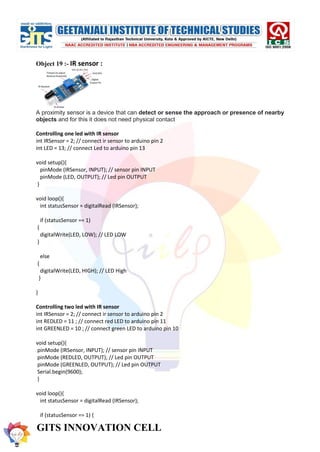
  • 33. GITS INNOVATION CELL Object 19 :- IR sensor : A proximity sensor is a device that can detect or sense the approach or presence of nearby objects and for this it does not need physical contact Controlling one led with IR sensor int IRSensor = 2; // connect ir sensor to arduino pin 2 int LED = 13; // connect Led to arduino pin 13 void setup(){ pinMode (IRSensor, INPUT); // sensor pin INPUT pinMode (LED, OUTPUT); // Led pin OUTPUT } void loop(){ int statusSensor = digitalRead (IRSensor); if (statusSensor == 1) { digitalWrite(LED, LOW); // LED LOW } else { digitalWrite(LED, HIGH); // LED High } } Controlling two led with IR sensor int IRSensor = 2; // connect ir sensor to arduino pin 2 int REDLED = 11 ; // connect red LED to arduino pin 11 int GREENLED = 10 ; // connect green LED to arduino pin 10 void setup(){ pinMode (IRSensor, INPUT); // sensor pin INPUT pinMode (REDLED, OUTPUT); // Led pin OUTPUT pinMode (GREENLED, OUTPUT); // Led pin OUTPUT Serial.begin(9600); } void loop(){ int statusSensor = digitalRead (IRSensor); if (statusSensor == 1) {
  • 34. GITS INNOVATION CELL Serial.print("IRSensor "); Serial.println(statusSensor); digitalWrite(GREENLED, HIGH); // Green LED is HIGH if IR sensor detect something } else { digitalWrite(REDLED, HIGH); // Red LED is HIGH if nothing is detected } }
  • 35. GITS INNOVATION CELL Object 20 :- PIR motion sensor : A passive infrared sensor (PIR sensor) is an electronic sensor that measures infrared (IR) light radiating from objects in its field of view. They are most often used in PIR-based motion detectors. PIR sensors are commonly used in security alarms and automatic lighting applications. PIR motion sensor with LED int led = 13; // the pin that the LED is atteched to int sensor = 2; // the pin that the sensor is atteched to int state = LOW; // by default, no motion detected int val = 0; // variable to store the sensor status (value) void setup() { pinMode(led, OUTPUT); // initalize LED as an output pinMode(sensor, INPUT); // initialize sensor as an input Serial.begin(9600); // initialize serial } void loop(){ val = digitalRead(sensor); // read sensor value if (val == HIGH) { // check if the sensor is HIGH digitalWrite(led, HIGH); // turn LED ON delay(500); // delay 100 milliseconds if (state == LOW) { Serial.println("Motion detected!"); state = HIGH; // update variable state to HIGH } } else { digitalWrite(led, LOW); // turn LED OFF delay(500); // delay 200 milliseconds if (state == HIGH){ Serial.println("Motion stopped!"); state = LOW; // update variable state to LOW } } }
  • 36. GITS INNOVATION CELL PIR motion sensor with buzzer //the time we give the sensor to calibrate (10-60 secs according to the datasheet) int calibrationTime = 30; //the time when the sensor outputs a low impulse long unsigned int lowIn; //the amount of milliseconds the sensor has to be low //before we assume all motion has stopped long unsigned int pause = 5000; boolean lockLow = true; boolean takeLowTime; int pirPin = 3; //the digital pin connected to the PIR sensor's output int ledPin = 13; ///////////////////////////// //SETUP void setup(){ Serial.begin(9600); pinMode(pirPin, INPUT); pinMode(ledPin, OUTPUT); digitalWrite(pirPin, LOW); //give the sensor some time to calibrate Serial.print("calibrating sensor "); for(int i = 0; i < calibrationTime; i++){ Serial.print("."); delay(1000); } Serial.println(" done"); Serial.println("SENSOR ACTIVE"); delay(50); } //////////////////////////// //LOOP void loop(){ if(digitalRead(pirPin) == HIGH){ digitalWrite(ledPin, HIGH); //the led visualizes the sensors output pin state if(lockLow){ //makes sure we wait for a transition to LOW before any further output is made: lockLow = false; Serial.println("---"); Serial.print("motion detected at "); Serial.print(millis()/1000);
  • 37. GITS INNOVATION CELL Serial.println(" sec"); delay(50); } takeLowTime = true; } if(digitalRead(pirPin) == LOW){ digitalWrite(ledPin, LOW); //the led visualizes the sensors output pin state if(takeLowTime){ lowIn = millis(); //save the time of the transition from high to LOW takeLowTime = false; //make sure this is only done at the start of a LOW phase } //if the sensor is low for more than the given pause, //we assume that no more motion is going to happen if(!lockLow && millis() - lowIn > pause){ //makes sure this block of code is only executed again after //a new motion sequence has been detected lockLow = true; Serial.print("motion ended at "); //output Serial.print((millis() - pause)/1000); Serial.println(" sec"); delay(50); } } }
  • 38. GITS INNOVATION CELL Object 21:- GSM SIM 900A SIM900A is an ultra compact and reliable wireless module. This is a complete GSM/GPRS module in a SMT type and designed with a very powerful single-chip processor integrating AMR926EJ-S core, allowing you to benefit from small dimensions and cost-effective solutions. #include <SoftwareSerial.h> SoftwareSerial mySerial(9,10); void setup() { mySerial.begin(9600); // Setting the baud rate of GSM Module Serial.begin(9600); // Setting the baud rate of Serial Monitor (Arduino) delay(100); } void loop() { if (Serial.available()>0) switch(Serial.read()) { case 's': SendMessage(); break; case 'r': RecieveMessage(); break; } if (mySerial.available()>0) Serial.write(mySerial.read()); } void SendMessage() { mySerial.println("AT+CMGF=1"); //Sets the GSM Module in Text Mode delay(1000); // Delay of 1000 milli seconds or 1 second mySerial.println("AT+CMGS="+919872436823"r"); // Replace x with mobile number delay(1000); mySerial.println("hi how are u doing?");// The SMS text you want to send delay(100); mySerial.println((char)26);// ASCII code of CTRL+Z delay(1000); } void RecieveMessage() { mySerial.println("AT+CNMI=2,2,0,0,0"); // AT Command to receive a live SMS
  • 40. GITS INNOVATION CELL Object 22 :- Motor with l298 motor driver int motor1pin1 = 2; int motor1pin2 = 3; int motor2pin1 = 4; int motor2pin2 = 5; void setup() { // put your setup code here, to run once: pinMode(motor1pin1, OUTPUT); pinMode(motor1pin2, OUTPUT); pinMode(motor2pin1, OUTPUT); pinMode(motor2pin2, OUTPUT); } void loop() { // put your main code here, to run repeatedly: digitalWrite(motor1pin1, HIGH); digitalWrite(motor1pin2, LOW); digitalWrite(motor2pin1, HIGH); digitalWrite(motor2pin2, LOW); delay(1000); digitalWrite(motor1pin1, LOW); digitalWrite(motor1pin2, HIGH); digitalWrite(motor2pin1, LOW); digitalWrite(motor2pin2, HIGH); delay(1000); }
  • 41. GITS INNOVATION CELL Object 22 :- Bluethooth with led Here's how to use HC-05 Bluetooth Module with Arduino. And build Android App using MIT App Inventor to control devices connected over Bluetooth. char Incoming_value = 0; void setup() { Serial.begin(9600); pinMode(13, OUTPUT); } void loop() { if(Serial.available() > 0) { Incoming_value = Serial.read(); Serial.print(Incoming_value); Serial.print("n"); if(Incoming_value == '1') digitalWrite(13, HIGH); else if(Incoming_value == '0') digitalWrite(13, LOW); } }
  • 42. GITS INNOVATION CELL Led control using voice command String voice; int RED = 2; int GREEN = 3; int BLUE = 4; void RedOn(){ digitalWrite (RED, HIGH); } void RedOff(){ digitalWrite (RED, LOW); } void GreenOn(){ digitalWrite (GREEN, HIGH); } void GreenOff(){ digitalWrite (GREEN, LOW); } void BlueOn(){ digitalWrite (BLUE, HIGH); } void BlueOff(){ digitalWrite (BLUE, LOW); } void allon() { digitalWrite (RED, HIGH); digitalWrite (GREEN, HIGH); digitalWrite (BLUE, HIGH); } void alloff() { digitalWrite (RED, LOW); digitalWrite (GREEN, LOW); digitalWrite (BLUE, LOW); } void setup() { Serial.begin(9600); pinMode(RED, OUTPUT); pinMode(GREEN, OUTPUT); pinMode(BLUE, OUTPUT); } void loop() {
  • 43. GITS INNOVATION CELL while(Serial.available()) { delay(10); char c=Serial.read(); if(c=='#') {break; } voice += c; } if (voice.length() > 0) { Serial.println(voice); if (voice == "on" || voice == "all") { allon() ; } else if (voice == "off" || voice=="all off") { alloff() ; } else if(voice =="red" || voice =="red on"){ RedOn(); } else if(voice =="red off"){ RedOff(); } else if(voice =="green" || voice =="green on"){ GreenOn(); } else if( voice =="green off" ){ GreenOff(); } else if(voice =="blue" || voice =="blue on"){ BlueOn(); } else if(voice =="blue off"){ BlueOff(); } voice=""; } }