2
Most read
4
Most read
13
Most read
Board support package on Linux

•Board support package or BSP is the set of
software used to initialize the hardware devices on
the board and implement the board specific
routines that can be used by the kernel and device
drivers alike.
•BSP is thus a hardware abstraction layer (HAL)
gluing the to the OS by hiding the details of the
processor/CPU and the board.
BSP components
•    The microprocessor support: Linux kernel has wide support for all
     the leading processors in the embedded market such as MIPS,
     ARM and PowerPC
•    The board-specific routines: A typical HAL for the board hardware
     will include:
    – Boot loader support
    – Memory map support
    – System timers
    – Interrupt controller support
    – Real-time clock (RTC)
    – Serial support (debug and console)
    – Bus support (PCI/I2C,USB, SD)
    – Power management
Kernel in BSP
• The linux HAL source code resides under “arch” and
  “include/asm-XXX” directory, where XXX is processor name
  such as ARM
• Under each processor directory, all boards based on that CPU
  are categorized again into the subdirectories such as
   – kernel: This directory contains the CPU-specific routines
     for initializing, IRQ set-up, interrupts etc
   – mm: Contains hardware specific TLB set-up and exception
     handling code.
The boot loader interface
•   The boot loader is the piece of software that starts executing immediately
    after the system is powered on.
•   Most of the boot-loading issues are specific to the CPU and the boards
    shipped out.
•   Boot loader functionalities can be divided into
     – Mandatory
          • Initializing the hardware: This includes the processor, the essential
            controllers such as the memory controller, and the hardware
            devices necessary for loading the kernel such as flash.
          • Loading the kernel: The necessary software to download the
            kernel and copy it to the appropriate memory location.
          • Passing arguments from the boot loader to the linux kernel
     – Optional
          • The optional boot loader functionalities are varied and depend on
            the customer usage.
Memory map
• The memory map defines the layout of the CPU’s addressable
  space.
• The memory map is needed for the following reasons:
   – It freezes on the address space allocated for various hardware
     components such as RAM, flash, and memory-mapped IO
     peripherals.
   – It highlights the allocation of onboard memory to various
     software components such as the boot loader and the kernel.
     This is crucial for building the software components; this
     information is fed normally via a linker script at the time of
     building.
   – It defines the virtual-to-physical address mapping for the board.
     This mapping is highly processor and board-specific; the design
     of the various onboard memory and bus controllers on the
     board decides this mapping.
Memory addresses seen on embedded linux systems

• There are three addresses that are seen on an embedded Linux system:
   – CPU un-translated or the physical address: This is the address that is
      seen on the actual memory bus.
   – CPU translated address or the virtual address: This is the address
      range that is recognized by the CPU as the valid address range. The
      main kernel memory allocator kmalloc(), for example, returns a virtual
      address. The virtual address goes through an MMU to get translated
      to a physical address.
   – Bus address: This is the address of memory as seen by devices other
      than the CPU. Depending on the bus, this address may vary.
• A memory map binds the memory layout of the system as seen by the
  CPU, the memory devices (RAM, flash, etc.), and the external devices;
• This map indicates how the devices having different views of the
  addressable space should communicate. In most of the platforms the bus
  address matches the physical address, but it is not mandatory.
• The Linux kernel provides macros to make sure that the device drivers are
  portable across all the platforms.
Memory map creation
• The creation of the memory map for the system can be broken
  down into the following tasks.
• The processor memory map: This is the first memory map that
  needs to be created. It explains the CPU’s memory management
  policies such as how the CPU handles the different address spaces
  (user mode, kernel mode), what are the caching policies for the
  various memory regions, and so on.
• The board memory map: Once there is an idea of how the
  processor sees the various memory areas, the next step is to fit the
  various onboard devices into the processor memory areas. This
  requires an understanding of the various onboard devices and the
  bus controllers.
• The software memory map: Next a portion of the memory needs to
  be given for the various software components such as the boot
  loader and the Linux kernel. The Linux kernel sets up its own
  memory map and decides where the various kernel sections such
  as code and heap will reside.
Board memory map
• Board memory map gives the mapping for various device
  memory space
• The following is the memory map designed for the Psuedo
  board that has 8 MB of onboard SDRAM, 4 MB of flash, and IO
  devices that require 2 MB of memory map range.
• 0x80000000 to 0x80800000: Used to map the 8 MB of
  SDRAM
• 0xBFC00000 to 0xC0000000: Used to map the 4 MB of flash
• 0xBF400000 to 0xBF600000: Used to map the 2 MB of IO
  peripherals
Software memory map
•   The 8 MB of SDRAM is made available for running both the boot loader and Linux
    kernel.
•   The Linux memory map setup is divided into following stages.
     – The Linux kernel layout — the linker script, how the various sections are laid
        out
     – The boot memory allocator
          • The boot memory allocators are the kernel dynamic allocators during the
            early stages of the kernel (before paging is set up); once paging is set up
            the zone allocators are responsible for dynamic memory allocation.
     – Creation of various memory allocator zones by the kernel
          • DMA Zone: This zone contains pages that undergo DMA
          • Normal Zone: This zone contains normal, regularly mapped , pages.
          • Highmem Zone: Many processors cannot access all of the physical
            memory because of the small size of the linear address space. This zone is
            used to map such memory into kernel address space.
Interrupt management
• Every board is unique with its hardware interrupt
  management, mostly because of the PIC (Programmable
  Interrupt Controller) interface.
• The Linux kernel treats all interrupts as logical interrupts;
  logical interrupts are directly connected to the processor or
  may go via a PIC.
• In both the cases when an interrupt is registered (via the
  request_irq() function), the device driver needs to pass an
  interrupt number as an argument that identifies the interrupt
  number; the interrupt number passed is that of the logical
  interrupt number
Timers
• There are two timers that need to be programmed by the
  BSP:
• The Programmable Interval Timer (PIT): This timer is hooked
  to the timer interrupt that provides the system pulse or ticks.
  For e.g. The default value for a tick on an X86 Linux system is
  1 msec. This is mandatory
• The Real-Time Clock (RTC): This is independent of the
  processor as it is an external chip on the board. The RTC is
  operated by a special battery that powers it, even when the
  board is switched off; thus once programmed it can provide
  the time of day services. This is not mandatory.
Power management
• Many types of embedded devices have different power
  requirements depending on their usage.
• Devices such as cell phones need to consume less energy so that
  battery life is not cut short.
• Linux provides power management framework and provide
  different policies to enforce power management.
• New embedded processors take these into account and offer two
  schemes:
   – dynamic frequency scaling and
   – dynamic voltage scaling.
• The modes offered by the CPUs are controlled typically by the OS,
  which can deduce the mode depending on the system load. The OS
  running on these systems can tune the processor’s power
  consumption depending on the system load.
• In case the processor is idling waiting for user events, it
  would be attending to minimal tasks necessary for the
  system such as servicing timer interrupts. If a
  processor supports idle mode, then the OS can put the
  CPU into the idle mode under such conditions.
• The idle mode is the mode where the various
  processor clocks are stopped (the clocks to the
  peripherals may be still active).
• Some processors go still further and offer another
  mode called the sleep mode wherein the power to the
  CPU and most of the peripherals is turned off.

More Related Content

PPTX
eMMC Embedded Multimedia Card overview
PPTX
Boot process
PDF
U-Boot - An universal bootloader
PDF
Build your own embedded linux distributions by yocto project
PPTX
Qnx os
PPTX
Over-the-air (OTA) updates and the Connected car
PPT
Computer hardware and its components
eMMC Embedded Multimedia Card overview
Boot process
U-Boot - An universal bootloader
Build your own embedded linux distributions by yocto project
Qnx os
Over-the-air (OTA) updates and the Connected car
Computer hardware and its components

What's hot (20)

PDF
Uboot startup sequence
PDF
Board Support Package Fact Sheet | Manual Guide
PDF
Part 01 Linux Kernel Compilation (Ubuntu)
PDF
Introduction To Linux Kernel Modules
PDF
Linux for embedded_systems
PPTX
Bootloaders (U-Boot)
PDF
Introduction to char device driver
PPT
U Boot or Universal Bootloader
PDF
Embedded Linux BSP Training (Intro)
PPT
U boot porting guide for SoC
PDF
Embedded Operating System - Linux
PPT
Basic Linux Internals
PPTX
Linux Initialization Process (2)
PPTX
U-Boot presentation 2013
PPTX
Linux device drivers
PPTX
Computer memory
PDF
File systems for Embedded Linux
Uboot startup sequence
Board Support Package Fact Sheet | Manual Guide
Part 01 Linux Kernel Compilation (Ubuntu)
Introduction To Linux Kernel Modules
Linux for embedded_systems
Bootloaders (U-Boot)
Introduction to char device driver
U Boot or Universal Bootloader
Embedded Linux BSP Training (Intro)
U boot porting guide for SoC
Embedded Operating System - Linux
Basic Linux Internals
Linux Initialization Process (2)
U-Boot presentation 2013
Linux device drivers
Computer memory
File systems for Embedded Linux
Ad

Similar to Board support package_on_linux (20)

PPTX
BSP.pptx
PPTX
Mces MOD 1.pptx
PPT
12429908.ppt
PPTX
Embedded systems 101 final
PPTX
Basics of Computer! BATRA COMPUTER CENTRE IN AMBALA
PPTX
esunit1.pptx
PPTX
fundamentals_IT_presentation computer peripherals basics
PPTX
Processors
PPTX
Lect 1_Embedded Linux Embedded RTOS ppt
PPTX
CISSP - Chapter 3 - CPU Architecture
PDF
Von Neumann Architecture
PPT
Data path of Computer Architecture ALU and other components
PPTX
introduction to embedded-converted new one
PDF
1 introduction
PPTX
Computer Organization: Introduction to Microprocessor and Microcontroller
PPT
Presentacion pujol
PPT
E.s unit 4 and 5
PDF
CPE UNIT I.pdf c Programming for engineers
PPTX
Chapter 02 system unit csc & tts
PPTX
Chap 3 CA.pptx
BSP.pptx
Mces MOD 1.pptx
12429908.ppt
Embedded systems 101 final
Basics of Computer! BATRA COMPUTER CENTRE IN AMBALA
esunit1.pptx
fundamentals_IT_presentation computer peripherals basics
Processors
Lect 1_Embedded Linux Embedded RTOS ppt
CISSP - Chapter 3 - CPU Architecture
Von Neumann Architecture
Data path of Computer Architecture ALU and other components
introduction to embedded-converted new one
1 introduction
Computer Organization: Introduction to Microprocessor and Microcontroller
Presentacion pujol
E.s unit 4 and 5
CPE UNIT I.pdf c Programming for engineers
Chapter 02 system unit csc & tts
Chap 3 CA.pptx
Ad

Recently uploaded (20)

PDF
Nurlina - Urban Planner Portfolio (english ver)
PPTX
ACFE CERTIFICATION TRAINING ON LAW.pptx
PDF
The TKT Course. Modules 1, 2, 3.for self study
PDF
FYJC - Chemistry textbook - standard 11.
PPTX
Cite It Right: A Compact Illustration of APA 7th Edition.pptx
PDF
Diabetes Mellitus , types , clinical picture, investigation and managment
PDF
Everyday Spelling and Grammar by Kathi Wyldeck
PDF
CAT 2024 VARC One - Shot Revision Marathon by Shabana.pptx.pdf
PPTX
pharmaceutics-1unit-1-221214121936-550b56aa.pptx
PDF
Compact First Student's Book Cambridge Official
PPTX
Theoretical for class.pptxgshdhddhdhdhgd
PDF
faiz-khans about Radiotherapy Physics-02.pdf
PPTX
IT infrastructure and emerging technologies
PPTX
Macbeth play - analysis .pptx english lit
PPTX
Power Point PR B.Inggris 12 Ed. 2019.pptx
PPTX
Neurological complocations of systemic disease
PDF
anganwadi services for the b.sc nursing and GNM
PDF
Chevening Scholarship Application and Interview Preparation Guide
PDF
Health aspects of bilberry: A review on its general benefits
PDF
Laparoscopic Dissection Techniques at WLH
Nurlina - Urban Planner Portfolio (english ver)
ACFE CERTIFICATION TRAINING ON LAW.pptx
The TKT Course. Modules 1, 2, 3.for self study
FYJC - Chemistry textbook - standard 11.
Cite It Right: A Compact Illustration of APA 7th Edition.pptx
Diabetes Mellitus , types , clinical picture, investigation and managment
Everyday Spelling and Grammar by Kathi Wyldeck
CAT 2024 VARC One - Shot Revision Marathon by Shabana.pptx.pdf
pharmaceutics-1unit-1-221214121936-550b56aa.pptx
Compact First Student's Book Cambridge Official
Theoretical for class.pptxgshdhddhdhdhgd
faiz-khans about Radiotherapy Physics-02.pdf
IT infrastructure and emerging technologies
Macbeth play - analysis .pptx english lit
Power Point PR B.Inggris 12 Ed. 2019.pptx
Neurological complocations of systemic disease
anganwadi services for the b.sc nursing and GNM
Chevening Scholarship Application and Interview Preparation Guide
Health aspects of bilberry: A review on its general benefits
Laparoscopic Dissection Techniques at WLH

Board support package_on_linux

  • 1. Board support package on Linux •Board support package or BSP is the set of software used to initialize the hardware devices on the board and implement the board specific routines that can be used by the kernel and device drivers alike. •BSP is thus a hardware abstraction layer (HAL) gluing the to the OS by hiding the details of the processor/CPU and the board.
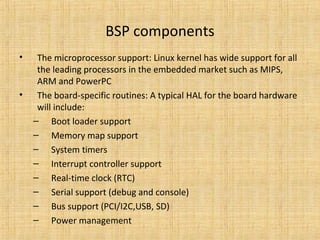
  • 2. BSP components • The microprocessor support: Linux kernel has wide support for all the leading processors in the embedded market such as MIPS, ARM and PowerPC • The board-specific routines: A typical HAL for the board hardware will include: – Boot loader support – Memory map support – System timers – Interrupt controller support – Real-time clock (RTC) – Serial support (debug and console) – Bus support (PCI/I2C,USB, SD) – Power management
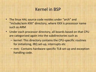
  • 3. Kernel in BSP • The linux HAL source code resides under “arch” and “include/asm-XXX” directory, where XXX is processor name such as ARM • Under each processor directory, all boards based on that CPU are categorized again into the subdirectories such as – kernel: This directory contains the CPU-specific routines for initializing, IRQ set-up, interrupts etc – mm: Contains hardware specific TLB set-up and exception handling code.
  • 4. The boot loader interface • The boot loader is the piece of software that starts executing immediately after the system is powered on. • Most of the boot-loading issues are specific to the CPU and the boards shipped out. • Boot loader functionalities can be divided into – Mandatory • Initializing the hardware: This includes the processor, the essential controllers such as the memory controller, and the hardware devices necessary for loading the kernel such as flash. • Loading the kernel: The necessary software to download the kernel and copy it to the appropriate memory location. • Passing arguments from the boot loader to the linux kernel – Optional • The optional boot loader functionalities are varied and depend on the customer usage.
  • 5. Memory map • The memory map defines the layout of the CPU’s addressable space. • The memory map is needed for the following reasons: – It freezes on the address space allocated for various hardware components such as RAM, flash, and memory-mapped IO peripherals. – It highlights the allocation of onboard memory to various software components such as the boot loader and the kernel. This is crucial for building the software components; this information is fed normally via a linker script at the time of building. – It defines the virtual-to-physical address mapping for the board. This mapping is highly processor and board-specific; the design of the various onboard memory and bus controllers on the board decides this mapping.
  • 6. Memory addresses seen on embedded linux systems • There are three addresses that are seen on an embedded Linux system: – CPU un-translated or the physical address: This is the address that is seen on the actual memory bus. – CPU translated address or the virtual address: This is the address range that is recognized by the CPU as the valid address range. The main kernel memory allocator kmalloc(), for example, returns a virtual address. The virtual address goes through an MMU to get translated to a physical address. – Bus address: This is the address of memory as seen by devices other than the CPU. Depending on the bus, this address may vary. • A memory map binds the memory layout of the system as seen by the CPU, the memory devices (RAM, flash, etc.), and the external devices; • This map indicates how the devices having different views of the addressable space should communicate. In most of the platforms the bus address matches the physical address, but it is not mandatory. • The Linux kernel provides macros to make sure that the device drivers are portable across all the platforms.
  • 7. Memory map creation • The creation of the memory map for the system can be broken down into the following tasks. • The processor memory map: This is the first memory map that needs to be created. It explains the CPU’s memory management policies such as how the CPU handles the different address spaces (user mode, kernel mode), what are the caching policies for the various memory regions, and so on. • The board memory map: Once there is an idea of how the processor sees the various memory areas, the next step is to fit the various onboard devices into the processor memory areas. This requires an understanding of the various onboard devices and the bus controllers. • The software memory map: Next a portion of the memory needs to be given for the various software components such as the boot loader and the Linux kernel. The Linux kernel sets up its own memory map and decides where the various kernel sections such as code and heap will reside.
  • 8. Board memory map • Board memory map gives the mapping for various device memory space • The following is the memory map designed for the Psuedo board that has 8 MB of onboard SDRAM, 4 MB of flash, and IO devices that require 2 MB of memory map range. • 0x80000000 to 0x80800000: Used to map the 8 MB of SDRAM • 0xBFC00000 to 0xC0000000: Used to map the 4 MB of flash • 0xBF400000 to 0xBF600000: Used to map the 2 MB of IO peripherals
  • 9. Software memory map • The 8 MB of SDRAM is made available for running both the boot loader and Linux kernel. • The Linux memory map setup is divided into following stages. – The Linux kernel layout — the linker script, how the various sections are laid out – The boot memory allocator • The boot memory allocators are the kernel dynamic allocators during the early stages of the kernel (before paging is set up); once paging is set up the zone allocators are responsible for dynamic memory allocation. – Creation of various memory allocator zones by the kernel • DMA Zone: This zone contains pages that undergo DMA • Normal Zone: This zone contains normal, regularly mapped , pages. • Highmem Zone: Many processors cannot access all of the physical memory because of the small size of the linear address space. This zone is used to map such memory into kernel address space.
  • 10. Interrupt management • Every board is unique with its hardware interrupt management, mostly because of the PIC (Programmable Interrupt Controller) interface. • The Linux kernel treats all interrupts as logical interrupts; logical interrupts are directly connected to the processor or may go via a PIC. • In both the cases when an interrupt is registered (via the request_irq() function), the device driver needs to pass an interrupt number as an argument that identifies the interrupt number; the interrupt number passed is that of the logical interrupt number
  • 11. Timers • There are two timers that need to be programmed by the BSP: • The Programmable Interval Timer (PIT): This timer is hooked to the timer interrupt that provides the system pulse or ticks. For e.g. The default value for a tick on an X86 Linux system is 1 msec. This is mandatory • The Real-Time Clock (RTC): This is independent of the processor as it is an external chip on the board. The RTC is operated by a special battery that powers it, even when the board is switched off; thus once programmed it can provide the time of day services. This is not mandatory.
  • 12. Power management • Many types of embedded devices have different power requirements depending on their usage. • Devices such as cell phones need to consume less energy so that battery life is not cut short. • Linux provides power management framework and provide different policies to enforce power management. • New embedded processors take these into account and offer two schemes: – dynamic frequency scaling and – dynamic voltage scaling. • The modes offered by the CPUs are controlled typically by the OS, which can deduce the mode depending on the system load. The OS running on these systems can tune the processor’s power consumption depending on the system load.
  • 13. • In case the processor is idling waiting for user events, it would be attending to minimal tasks necessary for the system such as servicing timer interrupts. If a processor supports idle mode, then the OS can put the CPU into the idle mode under such conditions. • The idle mode is the mode where the various processor clocks are stopped (the clocks to the peripherals may be still active). • Some processors go still further and offer another mode called the sleep mode wherein the power to the CPU and most of the peripherals is turned off.