SlideShare a Scribd company logo
CCNA exam
Enetwork
quangkien@gmail.com
Protocol and Reference Models
PDU
Encapsulation
OSI-TCP/IP Model
• Using a layered model:
– Fosters competition because products from different vendors can
work together
– Prevents changes in one layer from affecting other layers above
and below.
– Provides a common language to describe networking functions
and capabilities.
• There are two basic types of networking models: protocol models
and reference models.
• A protocol model provides a model that closely matches the
structure of a particular protocol suite. Example: TCP/IP.
• A reference model provides a common reference for maintaining
consistency within all types of network protocols and services
• The Open Systems Interconnection (OSI) model is the most widely
known internetwork reference model. It is used for data network
design, operation specifications, and troubleshooting.
TCP/IP
Application
The Presentation layer has
three primary functions:
Coding and
conversion
Compression
Encryption
Handles the exchange of
information to:
Initiate dialogs
Keep them active
Restart sessions that are
disrupted or idle for a long
period of time
• Application layer:
– Applications
– Services
HTTP
(WWW)
FTP
SMTP
(email)
Telnet
(file transfer)
(remote login)
DHCP
(IP address
resolution)
DNS
(file sharing)
P2P
(domain name
resolution)
(file sharing)
SMB
We will examine
HTTP in detail.
Server --- Client
Command : nslookup,
ipconfig /displaydns, ipconfig /flushdns
Transport Layer Role and Services
• Major functions of the transport layer and the role it plays in data
networks
– Tracking the individual communication between applications on the
source and destination hosts.
– Segmenting data and managing each piece.
– Reassembling the segments into streams of application data.
– Identifying the different applications
• Transport Layer:
– Responsible for creating and maintaining a logical connection
between the endpoints
• What are the two protocols at the transport layer?
– TCP – Transmission Control Protocol
– UDP – User Datagram Protocol
0 15 16 31
16-bit Source Port Number 16-bit Destination Port Number
32-bit Sequence Number
32 bit Acknowledgement Number
4-bit Header
Length
6-bit
(Reserved)
U
R
G
A
C
K
P
S
H
R
S
T
S
Y
N
F
I
N
16-bit Window Size
16-bit TCP Checksum 16-bit Urgent Pointer
Options (if any)
Data (if any)
Well Known or Registered
Port Number Private/Dynamic Port
Number
Well Known or Registered
Port Number
Private/Dynamic Port
Number
UDP Header
• C:Usersrigrazia>netstat -n
• Active Connections
• Proto Local Address Foreign Address State
• TCP 192.168.1.101:49888 198.133.219.25:80 TIME_WAIT
• TCP 192.168.1.101:49890 198.133.219.25:80 TIME_WAIT
• C:Usersrigrazia>
TCP
or
UDP
Source Port
Destination IP
Destination Port Connection State
Source IP
TCP/UDP
• Connectionless
transport
– No “handshaking” (no
connection
establishment) as with
TCP (coming)
– Unreliable delivery
– No error checking
– No flow control
– No congestion control
– No ordered delivery
• TCP provides reliable
delivery on top of
unreliable IP
• TCP provides:
– Reliable delivery
– Error checking
– Flow control
– Congestion control
– Ordered delivery
– Connection
establishment
CCNA Exam by quangkien@gmail.com - for CCNA test
TCP: Connection Establishment
0 15 16 31
16-bit Source Port Number 16-bit Destination Port Number
32-bit Sequence Number
32 bit Acknowledgement Number
4-bit Header
Length
6-bit
(Reserved)
U
R
G
A
C
K
P
S
H
R
S
T
S
Y
N
F
I
N
16-bit Window Size
16-bit TCP Checksum 16-bit Urgent Pointer
Options (if any)
Data (if any)
TCP uses window size and
acknowledgement to manage
data loss and congestion
during a session
• Step 1: Client sends ISN, SEQ=8563 (last four digits)
• Step 2: Server responds with ACK=8564, own ISN, SEQ=1678
• Step 3: Client sends ACK=1679
• Client now sends HTTP Request (GET) to Web Server
Network Layer
IPv4
0 15 16 31
4-bit
Version
4-bit
Header
Length
8-bit Type Of
Service
(TOS)
16-bit Total Length (in bytes)
16-bit Identification
3-bit
Flags 13-bit Fragment Offset
8 bit Time To Live
TTL
8-bit Protocol 16-bit Header Checksum
32-bit Source IP Address
32-bit Destination IP Address
Options (if any)
Data
Layer 3 uses four basic processes:
Addressing
Encapsulation
Routing
Decapsulation
IP Addresses – First look
• Host IP Address
– Unique host IP address
• Default Gateway
– A router which is used to forward packets out of the network.
– This is a host IP address on the router.
– Host IP address on the same network as the host.
• The host only has to be aware of:
– Its own network address
– Default gateway IP address to reach all devices outside its own network
Network Address 172.16.0.0
172.16.10.100/16
172.16.10.55/16
172.16.10.3/16
172.16.1.1/16
ISP
Internet
Network Address
192.168.1.0/30
192.168.1.2/30
192.168.1.1/30
Command : ipconfig /all
• Routers learn about remote networks using:
– Static routes
– Dynamic Routing Protocol (R = RIP)
• Routes in a routing table have three main features:
– Destination network
– Next-hop, exit interface
– Metric ( hop, cost )
192.168.1.254/24
C 192.168.2.0/24 is direction connected, FastEthernet0/1
Network 192.168.2.0/24
Network 192.168.1.0/24
Routing – First Look
Host Routing Table
• Hosts also have a local routing table.
• Usually only contains:
– Its own network address (directly connected network)
– Default gateway IP address
• Hosts usually do not have remote networks in their routing tables
netstat –r
or
route print
IPv4 hierarchical address
• 32 bits in four 8-bit octets, written in decimal
• Network part then host part
• Here network part (prefix) is 24 bits /24
• Length of network part can vary.
Mục đích ( giảm bảng định tuyến và dễ dàng quản trị )
Classfull /Classless IP
• Easy to work out but very
wasteful.
• Routers and hosts still
assume class subnet
masks by default
• Class A /8
255.0.0.0
• Class B /16
255.255.0.0
• Class C /24
255.255.255.0
• Any suitable prefix can be
used ( /20, /21, /7 … )
• We (and devices) need to
know what the prefix is.
• More flexible, less
wasteful.
Unicast, Multicast, Broadcast
• Unicast – a message addressed to one host
• Broadcast – a message addressed to all
hosts on a network. Uses network’s
broadcast address or 255.255.255.255
locally
• Multicast – a message addressed to a
group of hosts. Uses an address starting
224 - 239
Private IP addresses
• Unrestricted use on private networks. Not
routed across the Internet.
• 10.0.0.0 – 10.255.255.255 (10.0.0.0/8)
• 172.16.0.0 – 172.31.255.255
(172.16.0.0/20)
• 192.168.0.0 – 192.168.255.255
(192.168.0.0/24)
Public IP addresses
• Routed over the Internet
• Master holder is IANA
• Assigned to regional registries and then to
ISPs
• ISPs allocate them to organisations and
individual users
• Use is strictly controlled as duplicate
addresses are not allowed
Special addresses
• 0.0.0.0 “all addresses” in default route.
Hosts cannot be given addresses starting 0.
• 127.0.0.1 is loopback. Hosts cannot be
given addresses starting 127.
• 240.0.0.0 and higher – reserved for
experimental purposes.
• 169.254.0.0 - 169.254.255.255 local only
• 192.0.2.0 to 192.0.2.255 for teaching
ICMP: Ping and Trace
• Ping
• Uses ICMP message encapsulated within an IP Packet
– Protocol field = 1
• Both are layer 3 protocols. (ICMP is considered as a network layer protocol.)
• Does not use TCP or UDP, but may be acted upon by the receiver using TCP
or UDP.
• Format
• ping ip address (or ping <cr> for extended
ping)
• ping 172.30.1.25
Ethernet Header
(Layer 2)
IP Header
(Layer 3)
ICMP Message
(Layer 3)
Ether.
Tr.
Ethernet
Destination
Address
(MAC)
Ethernet
Source
Address
(MAC)
Frame
Type
Source IP Add.
Dest. IP Add.
Protocol field
Type
0 or 8
Code
0
Check-
sum
ID Seq.
Num.
Data FCS
Traceroute
• Traceroute is a utility that records the route (router IP addresses) between two devices
on different networks.
.
10.0.0.0/8 172.16.0.0/16 192.168.10.0/24
.1 .1 .1
.2 .2 .2
DA = 192.168.10.2, TTL = 1
DA = 192.168.10.2, TTL = 2
ICMP Time Exceeded, SA = 10.0.0.2
ICMP Time Exceeded, SA = 172.16.0.2
RTA RTB RTC RTD
Data Link Header
(Layer 2)
IP Header
(Layer 3)
ICMP Message - Echo Request (trace) UDP
(Layer 4)
DataLink
Tr.
Data Link
Destination
Address
Data Link
Source
Address
…… Source IP
Add.
10.0.0.1
Dest. IP Add.
192.168.10.2
Protocol field
1
TTL
2
Type
8
Code
0
Chk
sum
ID Seq.
Num
Data DestPort
35,000
FCS
Data Link Header
(Layer 2)
IP Header
(Layer 3)
ICMP Message - Echo Request (trace) UDP
(Layer 4)
DataLink
Tr.
Data Link
Destination
Address
Data Link
Source
Address
…… Source IP
Add.
10.0.0.1
Dest. IP Add.
192.168.10.2
Protocol field
1
TTL
1
Type
8
Code
0
Chk
sum
ID Seq.
Num
Data DestPort
35,000
FCS
Data Link Header
(Layer 2)
IP Header
(Layer 3)
ICMP Message - Time Exceeded DataLink
Tr.
Data Link
Destination
Address
Data Link
Source
Address
…. Source IP
Add.
172.16.0.2
Dest. IP Add.
10.0.0.1
Protocol field
1
Type
11
Code
0
Chk
sum
ID Seq
.
Nu
m.
Data FCS
RTA to RTB
RTB to RTC
IPv6
• Development started in 1990s because of concerns
about IPv4 addresses running out
• A whole new protocol suite – not just layer 3
• Uses 128-bit hierarchical addressing, written using
hexadecimal
• Simpler header
• Integrated security – authentication, privacy
• Quality of service mechanisms
CCNA Exam by quangkien@gmail.com - for CCNA test
Address Representation
• 128-bit IPv6 addresses are represented by
breaking them up into eight 16-bit segments.
• Each segment is written in hexadecimal
between 0x0000 and 0xFFFF, separated by
colons.
• An example of a written IPv6 address is
• 3ffe:1944:0100:000a:0000:00bc:2500:0
d0b
Rule 1: Leading 0’s
• Notice that only leading zeroes can be
omitted; trailing zeroes cannot, because
doing so would make the segment
ambiguous.
• You would not be able to tell whether the
missing zeroes belonged before or after the
written digits.
• 3ffe : 1944 : 100 : a : 0 : bc : 2500 :
d0b
Rule 2: Double colon :: equals 0000…0000
• The second rule can reduce this address even further:
• Any single, contiguous string of one or more 16-bit
segments consisting of all zeroes can be represented with
a double colon.
• ff02 : 0000 : 0000 : 0000 : 0000 : 0000 : 0000 : 0005
• ff02 : 0 : 0 : 0 : 0 : 0 : 0 : 5
• ff02 : : 5
• ff02::5
Rule 2: Double colon :: equals 0000…0000
• Only a single contiguous string of all-zero segments can be
represented with a double colon.
• Example: Both of these are correct
• 2001 : 0d02 : 0000 : 0000 : 0014 : 0000 : 0000 : 0095
• 2001 : d02 :: 14 : 0 : 0 : 95
• 2001 : d02 : 0 : 0 : 14 :: 95
• 2001 : 0d02 : 0000 : 0000 : 0014 : 0000 : 0000 : 0095
• 2001 : d02 :: 14 : 0 : 0 : 95
• OR
• 2001 : d02 : 0 : 0 : 14 :: 95
Correction in book
• The three types of
IPv6 address follow:
• Unicast
• Anycast
• Multicast.
Anycast Addresses
• A service is offered by three servers, all advertising the service at the IPv6 address
3ffe:205:1100::15.
• The router, receiving advertisements for the address, does not know that it is being
advertised by three different devices; instead, the router assumes that it has three routes
to the same destination and chooses the lowest-cost route.
• In this is the route to server C with a cost of 20.
Preferred
route
Multicast Addresses
NDP - Address Autoconfiguration
• When an IPv6 host first becomes active on a link, it can self-configure
its own interface address.
• The first step in this process is the determination of the 64-bit Interface
ID portion of the address.
• On broadcast interfaces (where hosts are most likely to appear), a
mechanism called MAC-to-EUI64 conversion is used.
• Quite simply, this mechanism:
– takes the 48-bit Media Access Control (MAC) address of the
interface—which can normally be assumed to be globally unique
– converts it into a 64-bit Interface ID by inserting a reserved 16-bit
value of 0xFFFE into the middle of the MAC address
– "flipping" the Universal/Local (U/L) bit of the MAC address to 1
(Universal).
NDP - Address Autoconfiguration – Interface ID
• Original MAC: 0000:0B0A:2D51
• Converted MAC: 0200:0BFF:FE0A:2D51
• LINK LOCAL Add: FF80::0200:0BFF:FE0A:2D51
FE80:: 0200:0BFF:FE0A:2D51
11111110 10000000 [& 48 0’s] Interface ID
[64 bits]
NDP - Address Autoconfiguration – Link Local Prefix
IPv6 Transition Strategies
Subnetting - visual
CCNA Exploration Semester 1
Subnets and Subnet Masks
Formalized in 1985, the subnet mask breaks
a single network in to smaller pieces.
 A “1” bit in the subnet mask means that the corresponding bit in the IP
address should be read as a network number
 A “0” bit in the subnet mask means that the corresponding bit in the IP
address should be read as a host bit.
 Allows network administrators to divide their network into small networks
or subnets.
 Advantages will be discussed later.
What is subnetting?
• Subnetting is the process of borrowing bits from the HOST bits, in order
to divide the larger network into small subnets.
• Subnetting does NOT give you more hosts, but actually costs you hosts.
• You lose two host IP Addresses for each subnet, one for the subnet IP
address and one for the subnet broadcast IP address.
• You lose the last subnet and all of it’s hosts’ IP addresses as the
broadcast for that subnet is the same as the broadcast for the network.
• In older technology, you would have lost the first subnet, as the subnet
IP address is the same as the network IP address. (This subnet can be
used in most networks.)
Network Network Host Host
172 16 0 0
Network Network Subnet Host
Subnet Example
Network address 172.16.0.0
Base Network Mask 255.255.0.0 or /16
• Applying a mask which is larger than the major network subnet mask, will
divide your network into subnets.
• Major network mask is 255.255.0.0 or /16
• Subnet mask used here is 255.255.255.0 or /24
Base Network Mask:
255.255.0.0 or /16
Subnet Mask:
255.255.255.0 or /24
11111111 11111111 00000000 00000000
11111111 11111111 11111111 00000000
Network Network Subnet Host
Network Network Host Host
Subnet Example
Network Network Subnet Host
Network address 172.16.0.0 with /16 Base Network Mask
172 16 0 0
172 16 1 0
172 16 2 0
Using Subnets: Subnet Mask 255.255.255.0 or /24
172 16 3 0
172 16 Etc. 0
172 16 254 0
172 16 255 0
255
Subnets
28 - 1
Cannot use last
subnet as it
contains broadcast
address
Subnets
Addresses
Subnet Example
Network Network Subnet Hosts
172 16 0 1
172 16 1 1
172 16 2 1
172 16 3 1
172 16 Etc. 1
172 16 254 1
172 16 255 Host
Each subnet has
254 hosts, 28 – 2
254
254
254
254
254
254
Broadcast
Network address 172.16.0.0 with /16 Base Network Mask
Using Subnets: Subnet Mask 255.255.255.0 or /24
255
255
255
255
255
255
Prefix /24
Three octets in network
part, last octet in host part.
All possible numbers 0 –
255 in last octet belong in
the same network.
Network address yellow
Broadcast address blue
Subnet mask
255.255.255.0
Prefix /25
First bit of fourth octet
taken into network part.
For every bit taken, double
number of networks, halve
their size.
Network address yellow
Broadcast address blue
Subnet mask
255.255.255.128
Prefix /26
2 bits of fourth octet taken
into network part.
For every bit taken, double
number of networks, halve
their size.
Network address yellow
Broadcast address blue
Subnet mask
255.255.255.192
Prefix /27
3 bits of fourth octet taken
into network part.
For every bit taken, double
number of networks, halve
their size.
Network address yellow
Broadcast address blue
Subnet mask
255.255.255.224
Prefix /28
4 bits of fourth octet taken
into network part.
For every bit taken, double
number of networks, halve
their size.
Network address yellow
Broadcast address blue
Subnet mask
255.255.255.240
Prefix /29
5 bits of fourth octet taken
into network part.
For every bit taken, double
number of networks, halve
their size.
Network address yellow
Broadcast address blue
Subnet mask
255.255.255.248
Prefix /30
6 bits of fourth octet taken
into network part.
For every bit taken, double
number of networks, halve
their size.
Network address yellow
Broadcast address blue
Subnet mask
255.255.255.252
Variable length
Networks do not need to
be all the same size.
/27
/26
/25
Data Link Layer
Ethernet,
PPP,
ISDN,
Frame
Relay
The Data Link layer provides a means for exchanging data over a common
local media.
Data Link Frame
• Typical field types may include:
– Start and stop indicator fields
– Addressing fields
– Type field - The type of PDU contained in the frame
– Quality - control fields
– Data field -The frame payload (Network layer packet)
•Framing breaks the stream into decipherable groupings, with control
information inserted in the header and trailer as values in different fields.
•This format gives the physical signals a structure that can be received by
nodes and decoded into packets at the destination.
Sublayer
OSI Physical layer
• OSI model layer 1
• TCP/IP model part of Network Access layer
Application
Presentation
Session
Transport
Network
Data link
Physical
Application
Transport
Internet
Network Access
TCP, UDP
IP
Ethernet,
WAN
technologies
HTTP, FTP,
TFTP, SMTP
etc
Segment
Packet
Frame
Bits
Data
stream
Media
• Copper cable (twisted
pair and coaxial)
• Fibre optic cable
• Wireless
Patch panel
Wall socket
Host Switch
5 metres 5 metres
90 metres
Horizontal cable
Patch cable
Patch cable
Total length of cable allowed for
UTP connection? 100 metres
Distance to allow between host and
switch or hub? 50 metres (cable runs
are not straight)
Distribution facility or
Telecommunications room
Horizontal and vertical cable
WAN connection
Customer’s router
Supplier’s device on
customer’s premises
provides clocking
V35 cable or
EIA/TIA-232
EIA/TIA-449
X21, V24,
HSSI
Supplier’s network
Simulating WAN in the lab
Straight through cable
• Both ends the same
• Connect PC to switch or
hub
• Connect router to switch
or hub
• Installed cabling is
straight through
Crossover cable
• Wire 1 swaps with 3
• Wire 2 swaps with 6
• Connect similar devices
to each other
• Connect PC direct to
router
Rollover cable
• Cisco proprietary
• Wire order completely
reversed
• Console connection from PC
serial port to router – to
configure router
• Special cable or RJ45 to D9
adaptor.
Ethernet
Type of Ethernet
The Ethernet MAC Address
Ethernet Unicast, Multicast & Broadcast
Media Access Control in Ethernet
• In a shared media environment, all devices have
guaranteed access to the medium, but they have no
prioritized claim on it.
–If more than one device transmits
simultaneously, the physical signals collide and
the network must recover in order for
communication to continue.
–Collisions are the cost that Ethernet pays to get
the low overhead associated with each
transmission.
• Ethernet uses Carrier Sense Multiple Access with
Collision Detection (CSMA/CD) to detect and handle
collisions and manage the resumption of
communications.
–Because all computers using Ethernet send
their messages on the same media, a distributed
coordination scheme (CSMA) is used to detect
the electrical activity on the cable.
–When a device detects that no other computer
is sending a frame, or carrier signal, the device
will transmit, if it has something to send.
CSMA/CD – The Process
• Carrier Sense
–In the CSMA/CD access method, all network devices that have
messages to send must listen before transmitting.
–If a device detects a signal from another device, it will wait for
a specified amount of time before attempting to transmit.
–When there is no traffic detected, a device will transmit its
message.
–While this transmission is occurring, the device continues to
listen for traffic or collisions on the LAN.
–After the message is sent, the device returns to its default
listening mode.
• Multi-access
–If the distance between devices is such that the one device's
signals are not detected by a second device, the second device
may start to transmit, too.
–The media now has two devices transmitting their signals at
the same time.
–Their messages will propagate across the media until they
encounter each other.
–At that point, the signals mix and the message is destroyed.
–Although the messages are corrupted, the jumble of remaining
signals continues to propagate across the media.
CSMA/CD – The Process
• Collision Detection
–The detection of a collision is made possible because all devices
can detect an increase in the amplitude of the signal above the
normal level.
–Once a collision occurs, the other devices in listening mode - as
well as all the transmitting devices - will detect the increase in the
signal amplitude.
–Once detected, every device transmitting will continue to transmit
to ensure that all devices on the network detect the collision.
• Jam Signal and Random Backoff
–Once the collision is detected by the transmitting devices, they
send out a jamming signal.
–This jamming signal is used to notify the other devices of a
collision, so that they will invoke a backoff algorithm.
–This backoff algorithm causes all devices to stop transmitting for a
random amount of time, which allows the collision signals to
subside.
–A random backoff period ensures that the devices that were
involved in the collision do not try to send their traffic again at the
same time, which would cause the whole process to repeat.
–But, this also means that a third device may transmit before either
of the two involved in the original collision have a chance to re-
transmit.
Collision Domain
Ethernet – Using Switches
• In a LAN where all nodes are connected directly to the
switch, the throughput of the network increases dramatically.
These physical star topologies are essentially point to point
links.
–Dedicated bandwidth to each port
•With switches, each device effectively has a
dedicated point-to-point connection between the
device and the switch, without media contention.
–Collision-free environment
•A dedicated point-to-point connection to a switch
also removes any media contention between devices,
allowing a node to operate with few or no collisions.
–In a moderately-sized classic Ethernet network
using hubs, approximately 40% to 50% of the
bandwidth is consumed by collision recovery.
–Full-duplex operation
•With full-duplex enabled in a switched Ethernet
network, the devices connected directly to the switch
ports can transmit and receive simultaneously, at the
full media bandwidth.
Switches – Selective Forwarding
• Switch forwarding is based on the Destination
MAC
–The switch maintains a table, called a MAC
table. that matches a destination MAC
address with the port used to connect to a
node.
–For each incoming frame, the destination
MAC address in the frame header is
compared to the list of addresses in the MAC
table.
–If a match is found, the port number in the
table that is paired with the MAC address is
used as the exit port for the frame.
• The MAC table can be referred to by many
different names.
–It is often called the switch table.
–Because switching was derived from
transparent bridging, the table is sometimes
called the bridge table.
Switches – store and forward
• Any node operating in full-duplex mode can transmit
anytime it has a frame, without regard to the
availability of the receiving node.
–This is because a LAN switch will buffer an
incoming frame and then forward it to the proper
port when that port is idle.
–This process is referred to as store and forward.
• With store and forward switching, the switch receives
the entire frame, checks the FSC for errors, and
forwards the frame to the appropriate port for the
destination node.
–Because the nodes do not have to wait for the
media to be idle, the nodes can send and receive
at full media speed without losses due to
collisions or the overhead associated with
managing collisions.
Switch Operation
• Ethernet LAN switches use 5 basic operations:
1. Learning
–The MAC table must be populated with MAC
addresses and their corresponding ports.
–The Learning process allows these mappings to be
dynamically acquired during normal operation.
–As each frame enters the switch, the switch examines
the source MAC address.
•If no entry exists, the switch creates a new entry in
the MAC table using the source MAC address and
pairs the address with the port on which the entry
arrived.
–The switch now can use this mapping to forward
frames to this node.
2. Aging
–The entries in the MAC table are time stamped.
–After entry made in MAC table, a countdown begins.
–After the value reaches 0, the entry in the table will be
removed.
Switch Operation
• Flooding
–If the switch does not know to which port to send a
frame because the destination MAC address is not in
the MAC table, the switch sends the frame to all ports
except the port on which the frame arrived.
–Flooding is also used for frames sent to the
broadcast MAC address.
• Selective Forwarding
–Selective forwarding is the process of examining a
frame's destination MAC address and forwarding it out
the appropriate port.
• Filtering
–One use of filtering has already been described: a
switch does not forward a frame to the same port on
which it arrived.
–A switch will also drop a corrupt frame. If a frame
fails a CRC check, the frame is dropped.
–An additional reason for filtering a frame is security.
–A switch has security settings for blocking frames to
and/or from selective MAC addresses.
Switches – Activity: page 9.6.4
3,3
1357,14
Please go to the
page and do more
exercise, until you
competently
understand the
topics.
The ARP Process – Mapping IP to MAC
Address
• The ARP protocol provides two basic functions:
• Resolving IPv4 Addresses to MAC Addresses
–For a frame to be placed on the LAN media, it must have a
destination MAC address.
–When a packet is sent to the Data Link layer to be
encapsulated into a frame, the node refers to a table in its
memory to find the Data Link layer address that is mapped to
the destination IPv4 address.
–This table is called the ARP table or the ARP cache.
–The ARP table is stored in the RAM of the device.
• Maintaining the ARP Table
–There are 2 ways that a device can gather MAC addresses.
•One way is to monitor the traffic occurs on the local
segment.
•Another way is to broadcast an ARP request.
–ARP sends a Layer 2 broadcast to all devices on the
Ethernet LAN. The frame contains an ARP request packet with
the IP address of the destination host.
•The node receiving the frame that identifies the IP
address as its own responds by sending an ARP reply
packet back to the sender as a unicast frame. This
response is then used to make a new entry in the ARP
table.
–These dynamic entries in the MAC table are timestamped.
ARP Process – Destinations not on the local
Network
• If the destination IPv4 host is not on the
local network, the source node needs to
deliver the frame to the router interface that
is the gateway or next hop used to reach
that destination.
–The source node will use the MAC
address of the gateway as the
destination address for frames
containing an IPv4 packet addressed to
hosts on other networks.
–In the event that the gateway entry is
not in the table, the normal ARP process
will send an ARP request to retrieve the
MAC address associated with the IP
address of the router interface.
Proxy ARP– Destinations not on the local
Network
• There are circumstances under which a host might send an
ARP request seeking to map an IPv4 address outside of the
range of the local network.
–In these cases, the device sends ARP requests for IPv4
addresses not on the local network instead of requesting
the MAC address with the IPv4 address of the gateway.
–To provide a MAC address for these hosts, a router use
a proxy ARP to respond on behalf of remote hosts.
–This means that the ARP cache of the requesting
device will contain the MAC address of the gateway
mapped to any IP addresses not on the local network.
–If proxy ARP is disabled on the router interface, these
hosts cannot communicate out of the local network.
• One such use of this process is
–IPv4 cannot determine whether the destination host is
on the same network as the source.
–When a host believes that it is directly connected to the
same network as the destination host. This generally
occurs when a host is configured with an improper mask.
–When a host is not configured with a default gateway.
Proxy ARP can help devices on a network reach remote
subnets.
http://www.cisco.com/warp/public/105/5.html
ARP Process – Removing Address Mapping
• For each device, an ARP cache timer removes
ARP entries that have not been used for a
specified period of time.
–The times differ depending on the device
and its operating system.
–For example, some Windows operating
systems store ARP cache entries for 2
minutes. If the entry is used again during
that time, the ARP timer for that entry is
extended to 10 minutes.
• Commands may also be used to manually
remove all or some of the entries in the ARP
table.
• After an entry has been removed, the process
for sending an ARP request and receiving an
ARP reply must occur again to enter the map in
the ARP table.
End
Thanks

More Related Content

Similar to CCNA Exam by [email protected] - for CCNA test (20)

PPTX
1.1.2 - Concept of Network and TCP_IP Model (2).pptx
VINAYTANWAR18
 
PPTX
IP Routing.pptx
ssuser957b41
 
PPTX
Network.pptx
SAMANTHACARDOSO13
 
PDF
aaaaaaaaaaaaaaaaaaaaaaaaaaaaaaaaaaaaaaaaaaaaaaaaaaaaa
madushanchashinka1
 
PDF
Clase 1 Direccionamiento IPv4.pdf
FERNANDOBONILLA43
 
PPTX
2 logical addressing
gafurov_x
 
PPTX
10 coms 525 tcpip - internet protocol - ip
Palanivel Kuppusamy
 
ODP
Your app lives on the network - networking for web developers
Wim Godden
 
PDF
Lecture set 7
Gopi Saiteja
 
PPT
TCP/IP Basics
SMC Networks Europe
 
PPTX
16.) layer 3 (basic tcp ip routing)
Jeff Green
 
PPTX
network-addressing.pptx
FidaBaloch8
 
PPT
SOHO Network Setup Tutorial
junaidahmedsaba
 
PDF
TCP-IP NETWORKING FOR WIRELESS SYSTEMS
BuddiesSairamit
 
PDF
Unit 2 - Internet Protocol Overview - IT
Deepraj Bhujel
 
PPT
Chapter 9 TCP IP Reference Model.ppt
hoangdinhhanh88
 
PPT
Chapter 9 TCP IP Reference Model.ppt
anwarkade1
 
PPTX
TCP/IP Protocol Architeture
Manoj Kumar
 
1.1.2 - Concept of Network and TCP_IP Model (2).pptx
VINAYTANWAR18
 
IP Routing.pptx
ssuser957b41
 
Network.pptx
SAMANTHACARDOSO13
 
aaaaaaaaaaaaaaaaaaaaaaaaaaaaaaaaaaaaaaaaaaaaaaaaaaaaa
madushanchashinka1
 
Clase 1 Direccionamiento IPv4.pdf
FERNANDOBONILLA43
 
2 logical addressing
gafurov_x
 
10 coms 525 tcpip - internet protocol - ip
Palanivel Kuppusamy
 
Your app lives on the network - networking for web developers
Wim Godden
 
Lecture set 7
Gopi Saiteja
 
TCP/IP Basics
SMC Networks Europe
 
16.) layer 3 (basic tcp ip routing)
Jeff Green
 
network-addressing.pptx
FidaBaloch8
 
SOHO Network Setup Tutorial
junaidahmedsaba
 
TCP-IP NETWORKING FOR WIRELESS SYSTEMS
BuddiesSairamit
 
Unit 2 - Internet Protocol Overview - IT
Deepraj Bhujel
 
Chapter 9 TCP IP Reference Model.ppt
hoangdinhhanh88
 
Chapter 9 TCP IP Reference Model.ppt
anwarkade1
 
TCP/IP Protocol Architeture
Manoj Kumar
 

Recently uploaded (20)

PPTX
Template Timeplan & Roadmap Product.pptx
ImeldaYulistya
 
PPTX
ipv6 very very very very vvoverview.pptx
eyala75
 
PPTX
1.10-Ruta=1st Term------------------------------1st.pptx
zk7304860098
 
PDF
Digital Security in 2025 with Adut Angelina
The ClarityDesk
 
PDF
123546568reb2024-Linux-remote-logging.pdf
lafinedelcinghiale
 
PPTX
英国学位证(RCM毕业证书)皇家音乐学院毕业证书如何办理
Taqyea
 
PDF
Apple_Environmental_Progress_Report_2025.pdf
yiukwong
 
PDF
Technical Guide to Build a Successful Shopify Marketplace from Scratch.pdf
CartCoders
 
PDF
How to Fix Error Code 16 in Adobe Photoshop A Step-by-Step Guide.pdf
Becky Lean
 
PPTX
英国假毕业证诺森比亚大学成绩单GPA修改UNN学生卡网上可查学历成绩单
Taqyea
 
PPTX
02 IoT Industry Applications and Solutions (1).pptx
abuizzaam
 
PPTX
一比一原版(SUNY-Albany毕业证)纽约州立大学奥尔巴尼分校毕业证如何办理
Taqyea
 
PDF
Slides PDF: ZPE - QFS Eco Economic Epochs pdf
Steven McGee
 
PPTX
Simplifying and CounFounding in egime.pptx
Ryanto10
 
PPTX
Internet_of_Things_Presentation_KaifRahaman.pptx
kaifrahaman27593
 
PDF
Pas45789-Energs-Efficient-Craigg1ing.pdf
lafinedelcinghiale
 
PPTX
Cost_of_Quality_Presentation_Software_Engineering.pptx
farispalayi
 
PPTX
原版西班牙莱昂大学毕业证(León毕业证书)如何办理
Taqyea
 
PPTX
本科硕士学历佛罗里达大学毕业证(UF毕业证书)24小时在线办理
Taqyea
 
PDF
The Power and Impact of Promotion most useful
RajaBilal42
 
Template Timeplan & Roadmap Product.pptx
ImeldaYulistya
 
ipv6 very very very very vvoverview.pptx
eyala75
 
1.10-Ruta=1st Term------------------------------1st.pptx
zk7304860098
 
Digital Security in 2025 with Adut Angelina
The ClarityDesk
 
123546568reb2024-Linux-remote-logging.pdf
lafinedelcinghiale
 
英国学位证(RCM毕业证书)皇家音乐学院毕业证书如何办理
Taqyea
 
Apple_Environmental_Progress_Report_2025.pdf
yiukwong
 
Technical Guide to Build a Successful Shopify Marketplace from Scratch.pdf
CartCoders
 
How to Fix Error Code 16 in Adobe Photoshop A Step-by-Step Guide.pdf
Becky Lean
 
英国假毕业证诺森比亚大学成绩单GPA修改UNN学生卡网上可查学历成绩单
Taqyea
 
02 IoT Industry Applications and Solutions (1).pptx
abuizzaam
 
一比一原版(SUNY-Albany毕业证)纽约州立大学奥尔巴尼分校毕业证如何办理
Taqyea
 
Slides PDF: ZPE - QFS Eco Economic Epochs pdf
Steven McGee
 
Simplifying and CounFounding in egime.pptx
Ryanto10
 
Internet_of_Things_Presentation_KaifRahaman.pptx
kaifrahaman27593
 
Pas45789-Energs-Efficient-Craigg1ing.pdf
lafinedelcinghiale
 
Cost_of_Quality_Presentation_Software_Engineering.pptx
farispalayi
 
原版西班牙莱昂大学毕业证(León毕业证书)如何办理
Taqyea
 
本科硕士学历佛罗里达大学毕业证(UF毕业证书)24小时在线办理
Taqyea
 
The Power and Impact of Promotion most useful
RajaBilal42
 
Ad

CCNA Exam by [email protected] - for CCNA test

  • 2. Protocol and Reference Models PDU Encapsulation
  • 3. OSI-TCP/IP Model • Using a layered model: – Fosters competition because products from different vendors can work together – Prevents changes in one layer from affecting other layers above and below. – Provides a common language to describe networking functions and capabilities. • There are two basic types of networking models: protocol models and reference models. • A protocol model provides a model that closely matches the structure of a particular protocol suite. Example: TCP/IP. • A reference model provides a common reference for maintaining consistency within all types of network protocols and services • The Open Systems Interconnection (OSI) model is the most widely known internetwork reference model. It is used for data network design, operation specifications, and troubleshooting.
  • 5. Application The Presentation layer has three primary functions: Coding and conversion Compression Encryption Handles the exchange of information to: Initiate dialogs Keep them active Restart sessions that are disrupted or idle for a long period of time • Application layer: – Applications – Services
  • 6. HTTP (WWW) FTP SMTP (email) Telnet (file transfer) (remote login) DHCP (IP address resolution) DNS (file sharing) P2P (domain name resolution) (file sharing) SMB We will examine HTTP in detail. Server --- Client
  • 7. Command : nslookup, ipconfig /displaydns, ipconfig /flushdns
  • 8. Transport Layer Role and Services • Major functions of the transport layer and the role it plays in data networks – Tracking the individual communication between applications on the source and destination hosts. – Segmenting data and managing each piece. – Reassembling the segments into streams of application data. – Identifying the different applications • Transport Layer: – Responsible for creating and maintaining a logical connection between the endpoints • What are the two protocols at the transport layer? – TCP – Transmission Control Protocol – UDP – User Datagram Protocol
  • 9. 0 15 16 31 16-bit Source Port Number 16-bit Destination Port Number 32-bit Sequence Number 32 bit Acknowledgement Number 4-bit Header Length 6-bit (Reserved) U R G A C K P S H R S T S Y N F I N 16-bit Window Size 16-bit TCP Checksum 16-bit Urgent Pointer Options (if any) Data (if any) Well Known or Registered Port Number Private/Dynamic Port Number Well Known or Registered Port Number Private/Dynamic Port Number UDP Header
  • 10. • C:Usersrigrazia>netstat -n • Active Connections • Proto Local Address Foreign Address State • TCP 192.168.1.101:49888 198.133.219.25:80 TIME_WAIT • TCP 192.168.1.101:49890 198.133.219.25:80 TIME_WAIT • C:Usersrigrazia> TCP or UDP Source Port Destination IP Destination Port Connection State Source IP
  • 11. TCP/UDP • Connectionless transport – No “handshaking” (no connection establishment) as with TCP (coming) – Unreliable delivery – No error checking – No flow control – No congestion control – No ordered delivery • TCP provides reliable delivery on top of unreliable IP • TCP provides: – Reliable delivery – Error checking – Flow control – Congestion control – Ordered delivery – Connection establishment
  • 13. TCP: Connection Establishment 0 15 16 31 16-bit Source Port Number 16-bit Destination Port Number 32-bit Sequence Number 32 bit Acknowledgement Number 4-bit Header Length 6-bit (Reserved) U R G A C K P S H R S T S Y N F I N 16-bit Window Size 16-bit TCP Checksum 16-bit Urgent Pointer Options (if any) Data (if any) TCP uses window size and acknowledgement to manage data loss and congestion during a session
  • 14. • Step 1: Client sends ISN, SEQ=8563 (last four digits)
  • 15. • Step 2: Server responds with ACK=8564, own ISN, SEQ=1678
  • 16. • Step 3: Client sends ACK=1679
  • 17. • Client now sends HTTP Request (GET) to Web Server
  • 18. Network Layer IPv4 0 15 16 31 4-bit Version 4-bit Header Length 8-bit Type Of Service (TOS) 16-bit Total Length (in bytes) 16-bit Identification 3-bit Flags 13-bit Fragment Offset 8 bit Time To Live TTL 8-bit Protocol 16-bit Header Checksum 32-bit Source IP Address 32-bit Destination IP Address Options (if any) Data Layer 3 uses four basic processes: Addressing Encapsulation Routing Decapsulation
  • 19. IP Addresses – First look • Host IP Address – Unique host IP address • Default Gateway – A router which is used to forward packets out of the network. – This is a host IP address on the router. – Host IP address on the same network as the host. • The host only has to be aware of: – Its own network address – Default gateway IP address to reach all devices outside its own network Network Address 172.16.0.0 172.16.10.100/16 172.16.10.55/16 172.16.10.3/16 172.16.1.1/16 ISP Internet Network Address 192.168.1.0/30 192.168.1.2/30 192.168.1.1/30 Command : ipconfig /all
  • 20. • Routers learn about remote networks using: – Static routes – Dynamic Routing Protocol (R = RIP) • Routes in a routing table have three main features: – Destination network – Next-hop, exit interface – Metric ( hop, cost ) 192.168.1.254/24 C 192.168.2.0/24 is direction connected, FastEthernet0/1 Network 192.168.2.0/24 Network 192.168.1.0/24 Routing – First Look
  • 21. Host Routing Table • Hosts also have a local routing table. • Usually only contains: – Its own network address (directly connected network) – Default gateway IP address • Hosts usually do not have remote networks in their routing tables netstat –r or route print
  • 22. IPv4 hierarchical address • 32 bits in four 8-bit octets, written in decimal • Network part then host part • Here network part (prefix) is 24 bits /24 • Length of network part can vary. Mục đích ( giảm bảng định tuyến và dễ dàng quản trị )
  • 23. Classfull /Classless IP • Easy to work out but very wasteful. • Routers and hosts still assume class subnet masks by default • Class A /8 255.0.0.0 • Class B /16 255.255.0.0 • Class C /24 255.255.255.0 • Any suitable prefix can be used ( /20, /21, /7 … ) • We (and devices) need to know what the prefix is. • More flexible, less wasteful.
  • 24. Unicast, Multicast, Broadcast • Unicast – a message addressed to one host • Broadcast – a message addressed to all hosts on a network. Uses network’s broadcast address or 255.255.255.255 locally • Multicast – a message addressed to a group of hosts. Uses an address starting 224 - 239
  • 25. Private IP addresses • Unrestricted use on private networks. Not routed across the Internet. • 10.0.0.0 – 10.255.255.255 (10.0.0.0/8) • 172.16.0.0 – 172.31.255.255 (172.16.0.0/20) • 192.168.0.0 – 192.168.255.255 (192.168.0.0/24)
  • 26. Public IP addresses • Routed over the Internet • Master holder is IANA • Assigned to regional registries and then to ISPs • ISPs allocate them to organisations and individual users • Use is strictly controlled as duplicate addresses are not allowed
  • 27. Special addresses • 0.0.0.0 “all addresses” in default route. Hosts cannot be given addresses starting 0. • 127.0.0.1 is loopback. Hosts cannot be given addresses starting 127. • 240.0.0.0 and higher – reserved for experimental purposes. • 169.254.0.0 - 169.254.255.255 local only • 192.0.2.0 to 192.0.2.255 for teaching
  • 28. ICMP: Ping and Trace
  • 29. • Ping • Uses ICMP message encapsulated within an IP Packet – Protocol field = 1 • Both are layer 3 protocols. (ICMP is considered as a network layer protocol.) • Does not use TCP or UDP, but may be acted upon by the receiver using TCP or UDP. • Format • ping ip address (or ping <cr> for extended ping) • ping 172.30.1.25 Ethernet Header (Layer 2) IP Header (Layer 3) ICMP Message (Layer 3) Ether. Tr. Ethernet Destination Address (MAC) Ethernet Source Address (MAC) Frame Type Source IP Add. Dest. IP Add. Protocol field Type 0 or 8 Code 0 Check- sum ID Seq. Num. Data FCS
  • 30. Traceroute • Traceroute is a utility that records the route (router IP addresses) between two devices on different networks.
  • 31. . 10.0.0.0/8 172.16.0.0/16 192.168.10.0/24 .1 .1 .1 .2 .2 .2 DA = 192.168.10.2, TTL = 1 DA = 192.168.10.2, TTL = 2 ICMP Time Exceeded, SA = 10.0.0.2 ICMP Time Exceeded, SA = 172.16.0.2 RTA RTB RTC RTD Data Link Header (Layer 2) IP Header (Layer 3) ICMP Message - Echo Request (trace) UDP (Layer 4) DataLink Tr. Data Link Destination Address Data Link Source Address …… Source IP Add. 10.0.0.1 Dest. IP Add. 192.168.10.2 Protocol field 1 TTL 2 Type 8 Code 0 Chk sum ID Seq. Num Data DestPort 35,000 FCS Data Link Header (Layer 2) IP Header (Layer 3) ICMP Message - Echo Request (trace) UDP (Layer 4) DataLink Tr. Data Link Destination Address Data Link Source Address …… Source IP Add. 10.0.0.1 Dest. IP Add. 192.168.10.2 Protocol field 1 TTL 1 Type 8 Code 0 Chk sum ID Seq. Num Data DestPort 35,000 FCS Data Link Header (Layer 2) IP Header (Layer 3) ICMP Message - Time Exceeded DataLink Tr. Data Link Destination Address Data Link Source Address …. Source IP Add. 172.16.0.2 Dest. IP Add. 10.0.0.1 Protocol field 1 Type 11 Code 0 Chk sum ID Seq . Nu m. Data FCS RTA to RTB RTB to RTC
  • 32. IPv6 • Development started in 1990s because of concerns about IPv4 addresses running out • A whole new protocol suite – not just layer 3 • Uses 128-bit hierarchical addressing, written using hexadecimal • Simpler header • Integrated security – authentication, privacy • Quality of service mechanisms
  • 34. Address Representation • 128-bit IPv6 addresses are represented by breaking them up into eight 16-bit segments. • Each segment is written in hexadecimal between 0x0000 and 0xFFFF, separated by colons. • An example of a written IPv6 address is • 3ffe:1944:0100:000a:0000:00bc:2500:0 d0b
  • 35. Rule 1: Leading 0’s • Notice that only leading zeroes can be omitted; trailing zeroes cannot, because doing so would make the segment ambiguous. • You would not be able to tell whether the missing zeroes belonged before or after the written digits. • 3ffe : 1944 : 100 : a : 0 : bc : 2500 : d0b
  • 36. Rule 2: Double colon :: equals 0000…0000 • The second rule can reduce this address even further: • Any single, contiguous string of one or more 16-bit segments consisting of all zeroes can be represented with a double colon. • ff02 : 0000 : 0000 : 0000 : 0000 : 0000 : 0000 : 0005 • ff02 : 0 : 0 : 0 : 0 : 0 : 0 : 5 • ff02 : : 5 • ff02::5
  • 37. Rule 2: Double colon :: equals 0000…0000 • Only a single contiguous string of all-zero segments can be represented with a double colon. • Example: Both of these are correct • 2001 : 0d02 : 0000 : 0000 : 0014 : 0000 : 0000 : 0095 • 2001 : d02 :: 14 : 0 : 0 : 95 • 2001 : d02 : 0 : 0 : 14 :: 95 • 2001 : 0d02 : 0000 : 0000 : 0014 : 0000 : 0000 : 0095 • 2001 : d02 :: 14 : 0 : 0 : 95 • OR • 2001 : d02 : 0 : 0 : 14 :: 95
  • 38. Correction in book • The three types of IPv6 address follow: • Unicast • Anycast • Multicast.
  • 39. Anycast Addresses • A service is offered by three servers, all advertising the service at the IPv6 address 3ffe:205:1100::15. • The router, receiving advertisements for the address, does not know that it is being advertised by three different devices; instead, the router assumes that it has three routes to the same destination and chooses the lowest-cost route. • In this is the route to server C with a cost of 20. Preferred route
  • 41. NDP - Address Autoconfiguration • When an IPv6 host first becomes active on a link, it can self-configure its own interface address. • The first step in this process is the determination of the 64-bit Interface ID portion of the address. • On broadcast interfaces (where hosts are most likely to appear), a mechanism called MAC-to-EUI64 conversion is used. • Quite simply, this mechanism: – takes the 48-bit Media Access Control (MAC) address of the interface—which can normally be assumed to be globally unique – converts it into a 64-bit Interface ID by inserting a reserved 16-bit value of 0xFFFE into the middle of the MAC address – "flipping" the Universal/Local (U/L) bit of the MAC address to 1 (Universal).
  • 42. NDP - Address Autoconfiguration – Interface ID
  • 43. • Original MAC: 0000:0B0A:2D51 • Converted MAC: 0200:0BFF:FE0A:2D51 • LINK LOCAL Add: FF80::0200:0BFF:FE0A:2D51 FE80:: 0200:0BFF:FE0A:2D51 11111110 10000000 [& 48 0’s] Interface ID [64 bits] NDP - Address Autoconfiguration – Link Local Prefix
  • 45. Subnetting - visual CCNA Exploration Semester 1
  • 46. Subnets and Subnet Masks Formalized in 1985, the subnet mask breaks a single network in to smaller pieces.  A “1” bit in the subnet mask means that the corresponding bit in the IP address should be read as a network number  A “0” bit in the subnet mask means that the corresponding bit in the IP address should be read as a host bit.  Allows network administrators to divide their network into small networks or subnets.  Advantages will be discussed later.
  • 47. What is subnetting? • Subnetting is the process of borrowing bits from the HOST bits, in order to divide the larger network into small subnets. • Subnetting does NOT give you more hosts, but actually costs you hosts. • You lose two host IP Addresses for each subnet, one for the subnet IP address and one for the subnet broadcast IP address. • You lose the last subnet and all of it’s hosts’ IP addresses as the broadcast for that subnet is the same as the broadcast for the network. • In older technology, you would have lost the first subnet, as the subnet IP address is the same as the network IP address. (This subnet can be used in most networks.) Network Network Host Host 172 16 0 0 Network Network Subnet Host
  • 48. Subnet Example Network address 172.16.0.0 Base Network Mask 255.255.0.0 or /16 • Applying a mask which is larger than the major network subnet mask, will divide your network into subnets. • Major network mask is 255.255.0.0 or /16 • Subnet mask used here is 255.255.255.0 or /24 Base Network Mask: 255.255.0.0 or /16 Subnet Mask: 255.255.255.0 or /24 11111111 11111111 00000000 00000000 11111111 11111111 11111111 00000000 Network Network Subnet Host Network Network Host Host
  • 49. Subnet Example Network Network Subnet Host Network address 172.16.0.0 with /16 Base Network Mask 172 16 0 0 172 16 1 0 172 16 2 0 Using Subnets: Subnet Mask 255.255.255.0 or /24 172 16 3 0 172 16 Etc. 0 172 16 254 0 172 16 255 0 255 Subnets 28 - 1 Cannot use last subnet as it contains broadcast address Subnets Addresses
  • 50. Subnet Example Network Network Subnet Hosts 172 16 0 1 172 16 1 1 172 16 2 1 172 16 3 1 172 16 Etc. 1 172 16 254 1 172 16 255 Host Each subnet has 254 hosts, 28 – 2 254 254 254 254 254 254 Broadcast Network address 172.16.0.0 with /16 Base Network Mask Using Subnets: Subnet Mask 255.255.255.0 or /24 255 255 255 255 255 255
  • 51. Prefix /24 Three octets in network part, last octet in host part. All possible numbers 0 – 255 in last octet belong in the same network. Network address yellow Broadcast address blue Subnet mask 255.255.255.0
  • 52. Prefix /25 First bit of fourth octet taken into network part. For every bit taken, double number of networks, halve their size. Network address yellow Broadcast address blue Subnet mask 255.255.255.128
  • 53. Prefix /26 2 bits of fourth octet taken into network part. For every bit taken, double number of networks, halve their size. Network address yellow Broadcast address blue Subnet mask 255.255.255.192
  • 54. Prefix /27 3 bits of fourth octet taken into network part. For every bit taken, double number of networks, halve their size. Network address yellow Broadcast address blue Subnet mask 255.255.255.224
  • 55. Prefix /28 4 bits of fourth octet taken into network part. For every bit taken, double number of networks, halve their size. Network address yellow Broadcast address blue Subnet mask 255.255.255.240
  • 56. Prefix /29 5 bits of fourth octet taken into network part. For every bit taken, double number of networks, halve their size. Network address yellow Broadcast address blue Subnet mask 255.255.255.248
  • 57. Prefix /30 6 bits of fourth octet taken into network part. For every bit taken, double number of networks, halve their size. Network address yellow Broadcast address blue Subnet mask 255.255.255.252
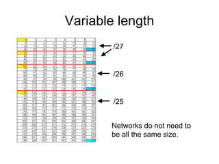
  • 58. Variable length Networks do not need to be all the same size. /27 /26 /25
  • 59. Data Link Layer Ethernet, PPP, ISDN, Frame Relay The Data Link layer provides a means for exchanging data over a common local media.
  • 60. Data Link Frame • Typical field types may include: – Start and stop indicator fields – Addressing fields – Type field - The type of PDU contained in the frame – Quality - control fields – Data field -The frame payload (Network layer packet) •Framing breaks the stream into decipherable groupings, with control information inserted in the header and trailer as values in different fields. •This format gives the physical signals a structure that can be received by nodes and decoded into packets at the destination.
  • 62. OSI Physical layer • OSI model layer 1 • TCP/IP model part of Network Access layer Application Presentation Session Transport Network Data link Physical Application Transport Internet Network Access TCP, UDP IP Ethernet, WAN technologies HTTP, FTP, TFTP, SMTP etc Segment Packet Frame Bits Data stream
  • 63. Media • Copper cable (twisted pair and coaxial) • Fibre optic cable • Wireless
  • 64. Patch panel Wall socket Host Switch 5 metres 5 metres 90 metres Horizontal cable Patch cable Patch cable Total length of cable allowed for UTP connection? 100 metres Distance to allow between host and switch or hub? 50 metres (cable runs are not straight) Distribution facility or Telecommunications room
  • 66. WAN connection Customer’s router Supplier’s device on customer’s premises provides clocking V35 cable or EIA/TIA-232 EIA/TIA-449 X21, V24, HSSI Supplier’s network
  • 67. Simulating WAN in the lab
  • 68. Straight through cable • Both ends the same • Connect PC to switch or hub • Connect router to switch or hub • Installed cabling is straight through
  • 69. Crossover cable • Wire 1 swaps with 3 • Wire 2 swaps with 6 • Connect similar devices to each other • Connect PC direct to router
  • 70. Rollover cable • Cisco proprietary • Wire order completely reversed • Console connection from PC serial port to router – to configure router • Special cable or RJ45 to D9 adaptor.
  • 73. The Ethernet MAC Address
  • 77. Media Access Control in Ethernet • In a shared media environment, all devices have guaranteed access to the medium, but they have no prioritized claim on it. –If more than one device transmits simultaneously, the physical signals collide and the network must recover in order for communication to continue. –Collisions are the cost that Ethernet pays to get the low overhead associated with each transmission. • Ethernet uses Carrier Sense Multiple Access with Collision Detection (CSMA/CD) to detect and handle collisions and manage the resumption of communications. –Because all computers using Ethernet send their messages on the same media, a distributed coordination scheme (CSMA) is used to detect the electrical activity on the cable. –When a device detects that no other computer is sending a frame, or carrier signal, the device will transmit, if it has something to send.
  • 78. CSMA/CD – The Process • Carrier Sense –In the CSMA/CD access method, all network devices that have messages to send must listen before transmitting. –If a device detects a signal from another device, it will wait for a specified amount of time before attempting to transmit. –When there is no traffic detected, a device will transmit its message. –While this transmission is occurring, the device continues to listen for traffic or collisions on the LAN. –After the message is sent, the device returns to its default listening mode. • Multi-access –If the distance between devices is such that the one device's signals are not detected by a second device, the second device may start to transmit, too. –The media now has two devices transmitting their signals at the same time. –Their messages will propagate across the media until they encounter each other. –At that point, the signals mix and the message is destroyed. –Although the messages are corrupted, the jumble of remaining signals continues to propagate across the media.
  • 79. CSMA/CD – The Process • Collision Detection –The detection of a collision is made possible because all devices can detect an increase in the amplitude of the signal above the normal level. –Once a collision occurs, the other devices in listening mode - as well as all the transmitting devices - will detect the increase in the signal amplitude. –Once detected, every device transmitting will continue to transmit to ensure that all devices on the network detect the collision. • Jam Signal and Random Backoff –Once the collision is detected by the transmitting devices, they send out a jamming signal. –This jamming signal is used to notify the other devices of a collision, so that they will invoke a backoff algorithm. –This backoff algorithm causes all devices to stop transmitting for a random amount of time, which allows the collision signals to subside. –A random backoff period ensures that the devices that were involved in the collision do not try to send their traffic again at the same time, which would cause the whole process to repeat. –But, this also means that a third device may transmit before either of the two involved in the original collision have a chance to re- transmit.
  • 81. Ethernet – Using Switches • In a LAN where all nodes are connected directly to the switch, the throughput of the network increases dramatically. These physical star topologies are essentially point to point links. –Dedicated bandwidth to each port •With switches, each device effectively has a dedicated point-to-point connection between the device and the switch, without media contention. –Collision-free environment •A dedicated point-to-point connection to a switch also removes any media contention between devices, allowing a node to operate with few or no collisions. –In a moderately-sized classic Ethernet network using hubs, approximately 40% to 50% of the bandwidth is consumed by collision recovery. –Full-duplex operation •With full-duplex enabled in a switched Ethernet network, the devices connected directly to the switch ports can transmit and receive simultaneously, at the full media bandwidth.
  • 82. Switches – Selective Forwarding • Switch forwarding is based on the Destination MAC –The switch maintains a table, called a MAC table. that matches a destination MAC address with the port used to connect to a node. –For each incoming frame, the destination MAC address in the frame header is compared to the list of addresses in the MAC table. –If a match is found, the port number in the table that is paired with the MAC address is used as the exit port for the frame. • The MAC table can be referred to by many different names. –It is often called the switch table. –Because switching was derived from transparent bridging, the table is sometimes called the bridge table.
  • 83. Switches – store and forward • Any node operating in full-duplex mode can transmit anytime it has a frame, without regard to the availability of the receiving node. –This is because a LAN switch will buffer an incoming frame and then forward it to the proper port when that port is idle. –This process is referred to as store and forward. • With store and forward switching, the switch receives the entire frame, checks the FSC for errors, and forwards the frame to the appropriate port for the destination node. –Because the nodes do not have to wait for the media to be idle, the nodes can send and receive at full media speed without losses due to collisions or the overhead associated with managing collisions.
  • 84. Switch Operation • Ethernet LAN switches use 5 basic operations: 1. Learning –The MAC table must be populated with MAC addresses and their corresponding ports. –The Learning process allows these mappings to be dynamically acquired during normal operation. –As each frame enters the switch, the switch examines the source MAC address. •If no entry exists, the switch creates a new entry in the MAC table using the source MAC address and pairs the address with the port on which the entry arrived. –The switch now can use this mapping to forward frames to this node. 2. Aging –The entries in the MAC table are time stamped. –After entry made in MAC table, a countdown begins. –After the value reaches 0, the entry in the table will be removed.
  • 85. Switch Operation • Flooding –If the switch does not know to which port to send a frame because the destination MAC address is not in the MAC table, the switch sends the frame to all ports except the port on which the frame arrived. –Flooding is also used for frames sent to the broadcast MAC address. • Selective Forwarding –Selective forwarding is the process of examining a frame's destination MAC address and forwarding it out the appropriate port. • Filtering –One use of filtering has already been described: a switch does not forward a frame to the same port on which it arrived. –A switch will also drop a corrupt frame. If a frame fails a CRC check, the frame is dropped. –An additional reason for filtering a frame is security. –A switch has security settings for blocking frames to and/or from selective MAC addresses.
  • 86. Switches – Activity: page 9.6.4 3,3 1357,14 Please go to the page and do more exercise, until you competently understand the topics.
  • 87. The ARP Process – Mapping IP to MAC Address • The ARP protocol provides two basic functions: • Resolving IPv4 Addresses to MAC Addresses –For a frame to be placed on the LAN media, it must have a destination MAC address. –When a packet is sent to the Data Link layer to be encapsulated into a frame, the node refers to a table in its memory to find the Data Link layer address that is mapped to the destination IPv4 address. –This table is called the ARP table or the ARP cache. –The ARP table is stored in the RAM of the device. • Maintaining the ARP Table –There are 2 ways that a device can gather MAC addresses. •One way is to monitor the traffic occurs on the local segment. •Another way is to broadcast an ARP request. –ARP sends a Layer 2 broadcast to all devices on the Ethernet LAN. The frame contains an ARP request packet with the IP address of the destination host. •The node receiving the frame that identifies the IP address as its own responds by sending an ARP reply packet back to the sender as a unicast frame. This response is then used to make a new entry in the ARP table. –These dynamic entries in the MAC table are timestamped.
  • 88. ARP Process – Destinations not on the local Network • If the destination IPv4 host is not on the local network, the source node needs to deliver the frame to the router interface that is the gateway or next hop used to reach that destination. –The source node will use the MAC address of the gateway as the destination address for frames containing an IPv4 packet addressed to hosts on other networks. –In the event that the gateway entry is not in the table, the normal ARP process will send an ARP request to retrieve the MAC address associated with the IP address of the router interface.
  • 89. Proxy ARP– Destinations not on the local Network • There are circumstances under which a host might send an ARP request seeking to map an IPv4 address outside of the range of the local network. –In these cases, the device sends ARP requests for IPv4 addresses not on the local network instead of requesting the MAC address with the IPv4 address of the gateway. –To provide a MAC address for these hosts, a router use a proxy ARP to respond on behalf of remote hosts. –This means that the ARP cache of the requesting device will contain the MAC address of the gateway mapped to any IP addresses not on the local network. –If proxy ARP is disabled on the router interface, these hosts cannot communicate out of the local network. • One such use of this process is –IPv4 cannot determine whether the destination host is on the same network as the source. –When a host believes that it is directly connected to the same network as the destination host. This generally occurs when a host is configured with an improper mask. –When a host is not configured with a default gateway. Proxy ARP can help devices on a network reach remote subnets. http://www.cisco.com/warp/public/105/5.html
  • 90. ARP Process – Removing Address Mapping • For each device, an ARP cache timer removes ARP entries that have not been used for a specified period of time. –The times differ depending on the device and its operating system. –For example, some Windows operating systems store ARP cache entries for 2 minutes. If the entry is used again during that time, the ARP timer for that entry is extended to 10 minutes. • Commands may also be used to manually remove all or some of the entries in the ARP table. • After an entry has been removed, the process for sending an ARP request and receiving an ARP reply must occur again to enter the map in the ARP table.