Chapter 2 programming concepts - I
Download as PPTX, PDF0 likes620 views

Chapter 2 covers assembly language programming, detailing the role of assemblers in translating symbolic source code into machine code and addressing the forward reference problem. It describes various assembler types, particularly for the x86 architecture, and outlines the features of models such as the tiny and small models used to define program structure. Additionally, the chapter discusses memory models, data definitions, and the design of instruction sets, specifically highlighting the complexities involved in instructions for the 8086 processor.


![THE RESULT OF ASSEMBLING AND LINKING (
DOS COMMAND WINDOW)
C:masm6.14BIN>ml tinym.asm
Microsoft (R) Macro Assembler Version 6.14.8444
Copyright (C) Microsoft Corp 1981-1997. All rights
reserved.
Assembling: tinym.asm
Microsoft (R) Segmented Executable Linker Version
5.60.339 Dec 5 1994
Copyright (C) Microsoft Corp 1984-1993. All rights
reserved.
Object Modules [.obj]: tinym.obj /t
Run File [tinym.com]: "tinym.com"
List File [nul.map]: NUL
Libraries [.lib]:
Definitions File [nul.def]:](https://image.slidesharecdn.com/chapter2-programmingconcepts-i-170612053749/85/Chapter-2-programming-concepts-I-14-320.jpg)


![COM AND EXE FILES
com files have only one segment (CS)
run file generated by the tiny model is a command
(.com) file, rather than an executable (.exe) file
shown in example 2.2 ; Run File [tiny.com]:
“tinym.com”
later seen that run files will be obtained as
‘executable’ with .exe
A tiny model generates only a com file ,
while any other memory model generates an exe file](https://image.slidesharecdn.com/chapter2-programmingconcepts-i-170612053749/85/Chapter-2-programming-concepts-I-20-320.jpg)


Chapter 2 programming concepts - I
- 2. ASSEMBLY LANGUAGE PROGRAMMING To code efficiently in assembly language for a particular processor ,the prerequisites are a good knowledge of the internal architecture of the processor and addressing modes
- 3. THE ASSEMBLY PROCESS An assembler is a translator that translates source instructions( in symbolic language) into target instructions (in machine language) on a one to one basis.
- 4. FEATURES OF ASSEMBLERS Labels are used for memory addresses Labels are used for constants Macros are allowed
- 5. INSTRUCTIONS AND DIRECTIVES Instructions are executable statements Directives are non-executable . Directives are also called pseudo instructions. Directives aid the assembly process.
- 6. WHAT THE ASSEMBLER DOES It takes the source code (in assembly language) and converts it to the object code in machine language
- 7. THE FORWARD REFERENCE PROBLEM In assemblers ,when a label which has not yet been defined ,is encountered, it is called the forward reference problem or future symbol problem or the problem of unresolved references .
- 8. PASSES OF AN ASSEMBLER In the first reading or ‘pass’ of the assembler , it looks for label definitions and inserts them in the symbol table after assigning them addresses . In pass 2 , the actual translation of assembly code to machine code is done .
- 9. ASSEMBLERS FOR X86 NASM ,FASM ,MASM ,TASM and HLA FASM and NASM –can run under DOS, Linux and Windows TASM and MASM are very popular It is found now that Windows 7 ,8 etc do not directly support DOS based 16 bit programs – so 16 bit assemblers may not work with Windows 7 directly.
- 10. WHY MASM ? Microsoft has written considerable documentation Third parties have written assembly language reference manuals for MASM. The versions of MASM 6.0 and above have a lot more features (aimed at simplification in writing code )than previous versions . Working Principle ?
- 11. MEMORY MODELS To write programs, we have to define segments where segment registers must be initialized Will take to use the full segment model MASM 6.0 and above have incorporated certain shortcuts to make programme simple They are called Dot Models. To specify a segment ,write . MODEL MODEL NAME Different models tell the assemble how to use segements and to provide sufficient space for the object code. simplest way is tiny model and small model
- 12. Tiny model is used when code, data and stack will all fit into one segment with maximum of 64 K Small model can have one data segment and one code segment each of which has a maximum size of 64 K TINY Model Program .MODEL TINY ;choose single segment model .CODE ; start of code segment .STARTUP ; start of program MOV AL,67H ; move 67H to AL MOV BL,45H ; move 45H to BL ADD AL,BL ; add BL to DL MOV DL,AL ; copy AL to DL .EXIT ; exit to DOS END ; program end
- 13. Save it a as tiny.asm Open MASM and go to the BIN directory.Use the following commands ml tinym.asm ;for assembling and linking ml/Fl tinym.asm ;for the list file
- 14. THE RESULT OF ASSEMBLING AND LINKING ( DOS COMMAND WINDOW) C:masm6.14BIN>ml tinym.asm Microsoft (R) Macro Assembler Version 6.14.8444 Copyright (C) Microsoft Corp 1981-1997. All rights reserved. Assembling: tinym.asm Microsoft (R) Segmented Executable Linker Version 5.60.339 Dec 5 1994 Copyright (C) Microsoft Corp 1984-1993. All rights reserved. Object Modules [.obj]: tinym.obj /t Run File [tinym.com]: "tinym.com" List File [nul.map]: NUL Libraries [.lib]: Definitions File [nul.def]:
- 15. EXAMPLE SHOWING LIST FILE .MODEL TINY ; choose single segment model 0000 .CODE ; start of code segment .STARTUP ; start of program 0100 B0 67 MOV AL,67H ; move 67H to AL 0102 B3 45 MOV BL,45H ; move 45H to BL 0104 02 C3 ADD AL,BL ; Add BL to AL 0106 8A D0 MOV DL,AL ; copy AL to DL .EXIT ; Exit to DOS END ; assembler to stop reading •On the left hand side, we see the offsets within the code segments in which the code is saved. • offsets are generated by assemblers •We also see opcodes corresponding to each instruction • example (1st Instruction), 0100H is the offset in the code segment where the first instruction is stored • BO 67 is the opcode of MOV AL, BH
- 16. if we add directive.listall, the list file is changed as shown below,
- 17. .Listall has listed the instructions corresponding to .EXIT .EXIT is a shortcut, which is actually transformed to two instructions: MOV AH,4CH INT 21H
- 18. USING THE DEBUGGER To enter the debugger ,type debug tinym.com . We get an underscore as the prompt. On typing ‘r’, we can see the contents of the registers ,before execution of the program . Now type ‘u’, which is the command for unassembling. (i.e Logical address of the first instruction)
- 19. C:masm6.14BIN>debug tinym.com -r AX=0000 BX=0000 CX=010C DX=0000 SP=0000 BP=0000 SI=0000 DI=0000 DS=13AD ES=13AD SS=13BD CS=13BD IP=0100 NV UP EI PL NZ NA PO NC 13BD:0100 B067 MOV AL,67 -u 13BD:0100 B067 MOV AL,67 13BD:0102 B345 MOV BL,45 13BD:0104 02C3 ADD AL,BL 13BD:0106 8AD0 MOV DL,AL 13BD:0108 B44C MOV AH,4C 13BD:010A CD21 INT 21
- 20. COM AND EXE FILES com files have only one segment (CS) run file generated by the tiny model is a command (.com) file, rather than an executable (.exe) file shown in example 2.2 ; Run File [tiny.com]: “tinym.com” later seen that run files will be obtained as ‘executable’ with .exe A tiny model generates only a com file , while any other memory model generates an exe file
- 21. FEATURES OF A COM FILE Size is limited to 64K Only one segment ,which is the code segment Data is defined in this code segment Code starts at offset 0100 H ,just after the PSP (program prefix segment ) of DOS Smaller file compared to exe files ,because it does not have the 512 byte header block
- 22. previous examples have seen the tactics of running and analysing a single segment assembly language program running in MASM We see now, the listing corresponding to another program which uses tiny model
- 23. Above Eg, shows a sequence of instructions that copy various data between 16 and 8-bit registers The act of moving data from one register to another changes only the destination register, never the source.
- 24. Listing and it shows various assembly language instructions that use immediate addressing only 8-bit can be placed into 8-bit register 16 bit copied to 16 bit registers look at 2nd instruction
- 25. MOV AL, C here assembler translates ASCII ‘C’ to its hex equivalent 43H all data written in memory will be in hex format Thus, the decimal 45 is found to 2DH in the listing A data (byte, word) starting with the hex character A,B,C,D,E,F must be preceded by a 0. else it gives error i.e MOV AL, EFH gives assembly error shud be rewritten as MOV AL, 0EFH Similarly MOV BX, C456H as MOV BX, 0C456H
- 26. DEFINITION OF DATA TYPES Before we go to two-segment model need to understand a few directives of the assembler, that describes different kinds of data May be Bytes, Words etc.. We have to define data and assign labels to their corresponding addresses Defining data implies allocating space for data Data is accordingly using directives some of the Data Definitions used in MASM are:
- 27. Eg shows data being placed in code segment itself In tiny model, we can have data and code in the same segment, with the instruction that the size of the segemnt should not exceed 64Kbytes NUM1, NUM2 and NUM3 are locations which store data NUM1 is a byte location, while NUM2 and NUM3 are word locations
- 28. THE SMALL MODEL Here two segments are used – A code segment and a data segment
- 30. Data segment with labels and off sets corresponding
- 31. DUP DIRECTIVE is used to replicate a given number of characters. Eg, we need to fill up a number of locations in the data segment with the same word or byte NUMS DB 10 DUP(0) fills up with 0s the 10 byte locations starting with the label NUM STARS DB 5 DUP(‘#’) fills up 5-byte locations starting at location STARS, with the ASCII value of the character # BLANK DB 10 DUP(?) reserves 10-byte spaces starting from location with the label BLANK, but these are not initialized, means whatever data is there will remain same WRDS DW 4 DUP(FF0FH) fills up 4 word locations with the word FF0FH
- 32. EQU DIRECTIVE Used to equate names to constants The assembler just replaces the names by the values mentioned Eg: TEMP EQU 34 PRICE EQU 199
- 33. ORG DIRECTIVE ORG is a directive which means ‘origin’. In the context of assembly language programming, it can change the location of storage of data or code in memory i.e programmer gets the freedom to decide the offset of data or code when it is stored.
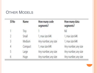
- 35. OTHER MODELS
- 36. FULL SEGMENT DEFINITION Is a traditional model of MASM In the simplified memory model, it is left to the loader software to initialize the segment registers In traditional model we use directives to define segments and instructions to initialize the segment registers This is called full segment definition CS & SS registers are automatically initialized by the loader DS & ES will have to be initialized by the programmer
- 37. LETS REWRITE THE BELOW PROGRAM USING FULL SEGMENT DEFINITION
- 39. SALIENT FEATURES OF THIS MODEL the data segment has been given the name DAT. The data within the segment is enclosed between the SEGMENT and ENDS directives which are similar to the parentheses for a segment similarly CS is named as COD and the contents of this segment also have been enclosed between the same directives DS register has been initialized by the first two instructions. DS cannot use immediate addressing. So DAT corresponds to a number, has to be loaded to AX, then transfer to DS The value of DAT is loaded into DS. CS register needs not to be initialized in the program. This is done by the loader by default.
- 40. INSTRUCTION DESIGN We have discussed about assemblers and how to run those programs Now lets study the core of the processor and investigate the process of how machine codes have been designed. Manual Coding is a idea of thinking the possibility of doing manual or hand coding, as it is called taking an assembly instructions, looking up or finding out its machine code, and feeding directly to the processor. It was happening during 8085 processor as it has limited instruction sets and look up table was sufficient for hand coding. Instruction Set Architecture (ISA) gives almost appropriate definition, defined as the part of computer architecture related to programming, including the native data types, instructions, registers, addressing modes, memory Arch., interrupt and exception handling, and external I/O. It includes a specification of the set of opcodes (machine language), i.e., the native commands implemented by a particular CPU design.
- 41. INSTRUCTION SET DESIGN OF 8086 8086 has instruction size varies from one byte to five bytes This makes the processes of assembly, disassembly and instruction decoding complicated because the instruction length needs to be calculated for each instruction. An instruction should have the complete information for fetching and executing an instruction. It should have the following information 1. Opcode corresponding to the operation carried out 2. Size of the Operands 3. Various addressing modes
- 42. FORMAT OF THREE BYTES OF AN INSTRUCTION
- 43. PREFIX: This is an optional byte and need to be used only to change the operation, e.g. segment override prefix
- 44. FIRST BYTE Considered as the first byte of an instruction Here the operation code (opcode) which is 6 bytes long. This is the code which defines the operation to be carried out. The two other bits are D & W W (1-bit) – operand size. W = 1, word operand; W = 0, means byte operand. D (1-bit) – Direction bit. D = 1, register is destination; D = 0, register is source
- 45. SECOND BYTE MOD (2-bit) – Register bits. REG (3-bit) – the identifying code of the register used. R/M (3 bits) – Specifying a register or memory operand. The MOD and R/M bits together specify the addressing mode of the instruction. All the instructions need not have the D & W bits. In such cases, the size of the operand is implicit, and the direction is irrelevant.
- 46. DESIGNING A CODE Requires a lot of information such as codes or registers a table showing the MOD and R/M bits corresponding to various combinations of addressing modes Intel manual for the opcodes and formats of instructions.
- 47. CODES OF GENERAL-PURPOSE REGISTERS
- 48. CODES OF SEGMENT REGISTERS
- 49. CODES PERTAINING TO ADDRESSING MODES – MOD AND R/M BIT PATTERNS