3. Introduction
Communication between electronics devices is like communication
between humans. Both sides need to speak the same language. In
electronics, these languages are called communications protocols.
4. Types of communication
Types of Data communication:
• Parallel: In parallel communication, all the bits of data are transmitted
simultaneously on separate communication lines.
• Serial: In serial communication the data bits are transmitted serially one by
one i.e. bit by bit on single communication line.
5. Types of Communication
Serial Communication uses two methods:
• Asynchronous.
• Synchronous.
Asynchronous:
1. Transfers single byte at a time.
2. No need of clock signal
3. Example: UART (universal asynchronous receiver transmitter)
Synchronous:
4. Transfers a block of data (characters) at a time.
5. Requires clock signal
6. Example: SPI (serial peripheral interface), I2C (inter integrated circuit).
6. UART Communication
In UART communication, two UARTs communicate directly with each other.
Only two wires are needed to transmit data between two UARTs. Data
flows from the Tx pin of the transmitting UART to the Rx pin of the receiving
UART:
Instead of a clock signal, the transmitting UART adds start and stop bits to
the data packet being transferred. These bits define the beginning and
end of the data packet so the receiving UART knows when to start reading
the bits.
7. How UART works
After the transmitting UART gets the parallel data from the data bus, it adds a start bit, a
parity bit, and a stop bit, creating the data packet. Next, the data packet is output serially,
bit by bit at the Tx pin. The receiving UART reads the data packet bit by bit at its Rx pin. The
receiving UART then converts the data back into parallel form and removes the start bit,
parity bit, and stop bits.
8. How UART works
The transmitting UART adds the start bit, parity bit, and the stop bit(s) to the data frame:
The entire packet is sent serially from the transmitting UART to the receiving UART.
9. How UART works
ADVANTAGES AND DISADVANTAGES OF UARTS
ADVANTAGES
1. Only uses two wires
2. No clock signal is necessary
3. Has a parity bit to allow for error checking
4. The structure of the data packet can be changed as long as both sides are set up for it
DISADVANTAGES
1. The size of the data frame is limited to a maximum of 9 bits
2. Doesn’t support multiple slave or multiple master systems
3. The baud rates of each UART must be within 10% of each other
10. SPI
Devices communicating via SPI are in a master-slave relationship. The master is the
controlling device (usually a microcontroller), while the slave (usually a sensor, display, or
memory chip) takes instruction from the master. The simplest configuration of SPI is a single
master, single slave system, but one master can control more than one slave
11. How SPI works
THE CLOCK
The clock signal synchronizes the output of data bits from the master to the sampling of bits
by the slave. One bit of data is transferred in each clock cycle, so the speed of data transfer
is determined by the frequency of the clock signal.
SLAVE SELECT
The master can choose which slave it wants to talk to by setting the slave’s CS/SS line to a
low voltage level.
MULTIPLE SLAVES
SPI can be set up to operate with a single master and a single slave, and it can be set up
with multiple slaves controlled by a single master.
13. How SPI works
ADVANTAGES AND DISADVANTAGES OF SPI
ADVANTAGES
1. No start and stop bits, so the data can be streamed continuously without interruption
2. No complicated slave addressing system like I2C
3. Higher data transfer rate than I2C (almost twice as fast)
4. Separate MISO and MOSI lines, so data can be sent and received at the same time
DISADVANTAGES
1. Uses four wires (I2C and UARTs use two)
2. No acknowledgement that the data has been successfully received (I2C has this)
3. No form of error checking like the parity bit in UART
4. Only allows for a single master
14. I2C
I2C combines the best features of SPI and UARTs. With I2C, you can
connect multiple slaves to a single master (like SPI) and you can have
multiple masters controlling single, or multiple slaves.
15. How I2C Works
With I2C, data is transferred in messages. Messages are broken up into frames of data.
Each message has an address frame that contains the binary address of the slave, and
one or more data frames that contain the data being transmitted. The message also
includes start and stop conditions, read/write bits, and ACK/NACK bits between each
data frame:
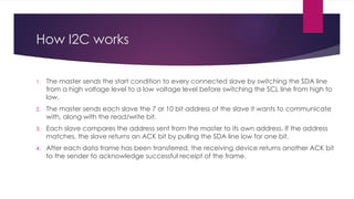
16. How I2C works
1. The master sends the start condition to every connected slave by switching the SDA line
from a high voltage level to a low voltage level before switching the SCL line from high to
low.
2. The master sends each slave the 7 or 10 bit address of the slave it wants to communicate
with, along with the read/write bit.
3. Each slave compares the address sent from the master to its own address. If the address
matches, the slave returns an ACK bit by pulling the SDA line low for one bit.
4. After each data frame has been transferred, the receiving device returns another ACK bit
to the sender to acknowledge successful receipt of the frame.
18. How I2C works
MULTIPLE MASTERS WITH MULTIPLE SLAVES
Multiple masters can be connected to a single slave or multiple slaves.
19. I2C
ADVANTAGES AND DISADVANTAGES OF I2C
ADVANTAGES
1. Only uses two wires
2. Supports multiple masters and multiple slaves
3. ACK/NACK bit gives confirmation that each frame is transferred successfully
4. Hardware is less complicated than with UARTs
5. Well known and widely used protocol
DISADVANTAGES
1. Slower data transfer rate than SPI
2. The size of the data frame is limited to 8 bits
3. More complicated hardware needed to implement than SPI
20. I2S
The protocol which is used to transmit digital audio data from one device to another
device is known as I2S or Inter-IC Sound protocol. This protocol transmits PCM (pulse-code
modulated) audio data from one IC to another within an electronic device.
Features
The I2S protocol features include the following.
1. It has 8 to 32 data bits for each sample.
2. Tx & Rx FIFO interrupts.
3. 16-bit, 32-bit, 48-bit, or 64-bit word select period.
4. Simultaneous bi-directional audio streaming.
5. It has different sample rates.
21. How I2S works
The I2S communication protocol is a 3 Wire protocol that simply handles audio data through a 3-line serial bus which
includes SCK (Continuous Serial Clock), WS (Word Select) & SD (Serial Data).
3-Wire Connection of I2S:
SCK
The SCK or Serial Clock is the first line of the I2S protocol which is also known as BCLK or bit clock line which is used to
obtain the data on a similar cycle.
WS
In the I2S communication protocol, the WS or word select is the line which is also known as FS (Frame Select)
wire that separates the right or left channel.
• If WS = 0 then left channel or channel-1 is used.
• If WS = 1 then the right channel or channel-2 is used.
SD
The Serial Data or SD is the last wire where the payload is transmitted within 2 complements. So, it is very significant
that the MSB is first transferred, because both the transmitter & receiver may include different word lengths. Thus, the
transmitter or the receiver has to recognize how many bits are transmitted.