Computer function-and-interconnection 3
Download as PPT, PDF3 likes7,057 views

The document provides a top-level overview of the basic components and functions of a computer system. It describes how a central processing unit (CPU) works with memory and input/output devices via buses to execute instructions. Interrupts allow efficient processing by suspending the current program to handle higher priority tasks or events before resuming the original program.


Computer function-and-interconnection 3
- 1. Top Level View of Computer Function and Interconnection
- 2. Program Concept Hardwired systems are inflexible General purpose hardware can do different tasks, given correct control signals Instead of re-wiring, supply a new set of control signals
- 3. What is a program? A sequence of steps For each step, an arithmetic or logical operation is done For each operation, a different set of control signals is needed
- 4. Function of Control Unit For each operation a unique code is provided e.g. ADD, MOVE A hardware segment accepts the code and issues the control signals We have a computer!
- 5. Components The Control Unit and the Arithmetic and Logic Unit constitute the Central Processing Unit Data and instructions need to get into the system and results out Input/output Temporary storage of code and results is needed Main memory
- 6. Computer Components: Top Level View
- 7. Instruction Cycle (Processing for a single instruction) Two steps: Fetch Execute Halt if machine is turned off, unrecoverable error
- 8. Fetch Cycle Program Counter (PC) holds address of next instruction to fetch Processor fetches instruction from memory location pointed to by PC Increment PC Unless told otherwise Instruction loaded into Instruction Register (IR) Processor interprets instruction and performs required actions
- 9. Execute Cycle Processor-memory Data transfer between CPU and main memory Processor I/O Data transfer between CPU and I/O module Data processing Some arithmetic or logical operation on data Control Alteration of sequence of operations e.g. jump Combination of above
- 10. Example of Program Execution
- 11. Instruction Cycle State Diagram
- 12. Interrupts Mechanism by which other modules (e.g. I/O) may interrupt normal sequence of processing Program e.g. overflow, division by zero Timer Generated by internal processor timer Used in pre-emptive multi-tasking I/O from I/O controller Task completion, variety of errors Hardware failure e.g. Power failure, memory parity error
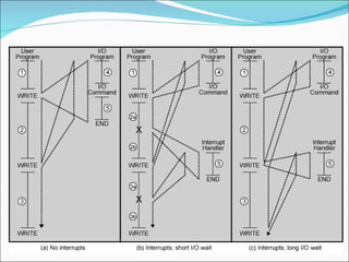
- 13. Interrupts A way to improve the processing efficiency Slow peripherals can not comprehend speedy processor Processor remains in stall state until device catches up Different tasks interleaved with WRITE Without interrupts, program would wait for IO to complete May Periodically pole the device. With interrupts, user can execute other instructions while IO is performed OS and Processor manage the suspension and resumption of program
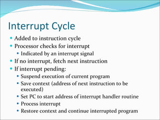
- 15. Interrupt Cycle Added to instruction cycle Processor checks for interrupt Indicated by an interrupt signal If no interrupt, fetch next instruction If interrupt pending: Suspend execution of current program Save context (address of next instruction to be executed) Set PC to start address of interrupt handler routine Process interrupt Restore context and continue interrupted program
- 16. In the Interrupt handler routine Fetch interrupt handler instructions from memory Interrupt handler routines are part of OS Extra instructions are executed but still save processing power
- 17. Transfer of Control via Interrupts
- 18. Instruction Cycle with Interrupts Hanggan d2 lng report ko mwaah
- 19. Program Timing Short I/O Wait
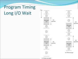
- 20. Program Timing Long I/O Wait
- 21. Instruction Cycle (with Interrupts) - State Diagram
- 22. Multiple Interrupts-I We may have more than one interrupts A program receiving data from communication line and printing data to a printing device Option to handle multiple interrupts
- 23. Multiple Interrupts-II Disable interrupts Processor will ignore further interrupts whilst processing one interrupt Interrupts remain pending and are checked after first interrupt has been processed Interrupts handled in sequence as they occur (No Priority task) Data arriving from communication line should be absorbed immediately Define priorities Low priority interrupts can be interrupted by higher priority interrupts When higher priority interrupt has been processed, processor returns to previous interrupt E.g. Printer 2, disk 4, communication line 5
- 24. Multiple Interrupts - Sequential
- 25. Multiple Interrupts – Nested
- 26. Time Sequence of Multiple Interrupts
- 27. Connecting All the units must be connected Different type of connection for different type of unit Memory Input/Output CPU Collection of paths connecting various structures are called interconnection structures.
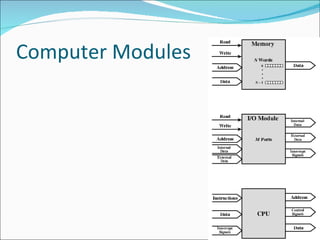
- 28. Computer Modules
- 29. Memory Connection Receives and sends data Receives addresses (of locations) Receives control signals Read Write Timing
- 30. Input/Output Connection(1) Similar to memory from computer’s viewpoint Output Receive data from computer Send data to peripheral Input Receive data from peripheral Send data to computer
- 31. Input/Output Connection(2) Receive control signals from computer Send control signals to peripherals e.g. spin disk Receive addresses from computer e.g. port number to identify peripheral Send interrupt signals (control)
- 32. CPU Connection Reads instruction and data Writes out data (after processing) Sends control signals to other units Receives (& acts on) interrupts
- 33. Buses There are a number of possible interconnection systems Single and multiple BUS structures are most common e.g. Control/Address/Data bus (PC) e.g. Unibus (DEC-PDP)
- 34. What is a Bus? A communication pathway connecting two or more devices Often grouped A number of channels in one bus e.g. 32 bit data bus is 32 separate single bit channels Power lines may not be shown
- 35. Data Bus Carries data Remember that there is no difference between “data” and “instruction” at this level Width is a key determinant of performance 8, 16, 32, 64 bit
- 36. Address bus Identify the source or destination of data e.g. CPU needs to read an instruction (data) from a given location in memory Bus width determines maximum memory capacity of system e.g. 8080 has 16 bit address bus giving 64k address space
- 37. Control Bus Control and timing information Memory read/write signal IO Read/Write Transfer Ack. Interrupt request (indicates interrupt is pending) Interrupt Ack. (pending intrrupt acknowledged) Sending and requesting data requires: Request use of bus Transfer of data via bus
- 39. Arrangement What do buses look like? Parallel lines on circuit boards Ribbon cables Strip connectors on mother boards On Chip and board wires
- 40. Physical Realization of Bus Architecture
- 41. Single Bus Problems Lots of devices on one bus leads to: Propagation delays Long data paths mean that co-ordination of bus use can adversely affect performance Bus may become a bottleneck as aggregate aggregate data transfer approaches bus capacity Increase the data rate (32-bit,64-bit) Still growing application demands can t be met Most systems use multiple buses to overcome these problems
- 43. Devices with high speed demand are closer to processor But independent of processor ( Processor’s Architectural changes have no affect on high speed bus)
- 44. Bus Types Dedicated Separate data & address lines Multiplexed (time multiplexing) Shared lines Address valid or data valid control line Advantage - fewer lines, cost benefit Disadvantages More complex control Ultimate performance Physical Dedication (IO bus connects IO modules only)
- 45. Bus Arbitration More than one module controlling the bus e.g. CPU and DMA controller Only one module may control bus at one time Arbitration may be centralised or distributed
- 46. Centralised or Distributed Arbitration Centralised Single hardware device controlling bus access Bus Controller Arbiter Distributed Each module may claim the bus Control logic on all modules
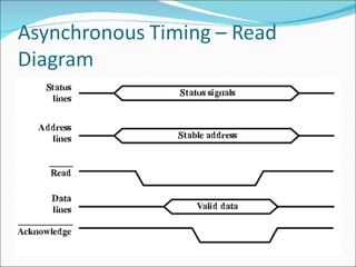
- 47. Timing Co-ordination of events on bus Synchronous Events determined by clock signals Control Bus includes clock line A single 1-0 is a bus cycle All devices can read clock line Usually sync on leading edge Usually a single cycle for an event
- 51. PCI Bus Peripheral Component Interconnection Intel released to public domain 32 or 64 bit 50 lines
- 52. PCI Bus Lines (required) Systems lines Including clock and reset Address & Data 32 time mux lines for address/data Interrupt & validate lines Interface Control Arbitration Not shared Direct connection to PCI bus arbiter Error lines
- 53. PCI Bus Lines (Optional) Interrupt lines Not shared Cache support 64-bit Bus Extension Additional 32 lines Time multiplexed 2 lines to enable devices to agree to use 64-bit transfer JTAG/Boundary Scan For testing procedures
- 54. PCI Commands Transaction between initiator (master) and target Master claims bus Determine type of transaction e.g. I/O read/write Address phase One or more data phases
- 58. Foreground Reading Stallings, chapter 3 (all of it) www.pcguide.com/ref/mbsys/buses/ In fact, read the whole site! www.pcguide.com/