


![• Encapsulation and Abstraction
Each pattern encapsulates a well-defined problem and its solution in a particular
domain.
• Openness and Variability
Each pattern should be open for extension or parametrization by other patterns so
that they may work together to solve a larger problem.
• Generativity and Composability
Each pattern, once applied, generates a resulting context which matches the initial
context of one or more other patterns in a pattern language. These subsequent
patterns may then be applied to progress further toward the final goal of
generating a "whole" or complete overall solution.
• Equilibrium
Each pattern must realize some kind of balance among its forces and constraints.
This may be due to one or more invariants or heuristics that are used to minimize
conflict within the solution space. The invariants often typify an underlying
problem solving principle or philosophy for the particular domain, and provide a
rationale for each step/rule in the pattern.
Patterns and Algorithms
• Algorithms and data structures may be employed in the implementation of one or
more patterns, but algorithms and data structures generally solve more fine-
grained computational problems like sorting and searching.
• Patterns are typically concerned with broader architectural issues that have larger-
scale effects. The design patterns in [GoF] address people and development issues
like maintainability, reusability, communicating commonality and encapsulation
variation. These are issues that matter to the people who need to create and
evolve/grow these software systems over time.
UIU Week 1, CSE 6087 6/23](https://image.slidesharecdn.com/cse-6007fall2012-121003234513-phpapp02/85/Cse-6007-fall2012-8-320.jpg)


![The [GoF] book describes the major differences between design patterns and frameworks
as follows:
• Design patterns are more abstract than frameworks. Frameworks can be
embodied in code, but only examples of patterns can be embodied in code. A
strength of frameworks is that they can be written down in programming
languages and not only studied but executed and reused directly. In contrast,
design patterns have to be implemented each time they are used. Design patterns
also explain the intent, trade-offs, and consequences of a design.
• Design patterns are smaller architectural elements than frameworks. A typical
framework contains several design patterns but the reverse is never true.
• Design patterns are less specialized than frameworks. Frameworks always have a
particular application domain. In constrast, design patterns can be used in nearly
any kind of application. While more specialized design patterns are certainly
possible, even these wouldn't dictate an application architecture.
UIU Week 1, CSE 6087 9/23](https://image.slidesharecdn.com/cse-6007fall2012-121003234513-phpapp02/85/Cse-6007-fall2012-11-320.jpg)


![Small Demo
Public class WorldCarSimulator
{
public static void main(string[] args)
{
Car Ferrari = new RaceCar();
Ferrari.carry();
Ferrari.race();
Ferrari.run();
Car RoadRunnerTaxi = new Taxi();
RoadRunnerTaxi.carry();
RoadRunnerTaxi.race();
//Changing the behaviour dynamically
RoadRunnerTaxi.setraceBehaviour(new RaceBehaviour());
RoadRunnerTaxi.race();
}
}
• When new thing comes we change outside of the class i.e. when new algorithm
comes (behavior), we need to implement that new behavior in a new interface not
in class level and that behavior can set dynamically using set method.
• Any class change their behavior outside of the class e.g.
//Changing the behaviour dynamically
RoadRunnerTaxi.setraceBehaviour(new RaceBehaviour());
RoadRunnerTaxi.race();
UIU Week 1, CSE 6087 19/23](https://image.slidesharecdn.com/cse-6007fall2012-121003234513-phpapp02/85/Cse-6007-fall2012-21-320.jpg)


![public class Database
{
private static Database singleObject;
private int record;
private String name;
private Database(String n) // Note private
{
name = n;
record = 0;
}
public static Database getInstance(String n) //
instantiation
{
if (singleObject == null){
singleObject = new Database(n);
}
return singleObject;
}
public void editRecord(String operation)
{
System.out.println("Performing a " + operation +
" operation on record " + record +
" in database " + name);
}
public String getName()
{
return name;
}
}
• The testing of the singleton pattern is as follows:
public class TestSingleton
{
public static void main(String args[])
{
Database database;
database = Database.getInstance("products");
System.out.println("This is the " +
database.getName() + " databse.");
database = Database.getInstance("employees");
System.out.println("This is the " +
database.getName() + " databse.");
}
}
UIU Week 3, CSE 6087 10/15](https://image.slidesharecdn.com/cse-6007fall2012-121003234513-phpapp02/85/Cse-6007-fall2012-54-320.jpg)

![public static synchronized DatabaseSynchronized
getInstance(String n)
{
if (singleObject == null){
singleObject = new DatabaseSynchronized(n);
}
return singleObject;
}
public void editRecord(String operation)
{
System.out.println("Performing a " + operation +
" operation on record " + record +
" in database " + name);
}
public String getName()
{
return name;
}
}
• The following class can be used to create the Singleton thread.
public class TestSingletonSynchronized implements Runnable
{
Thread thread;
public static void main(String args[])
{
TestSingletonSynchronized t = new
TestSingletonSynchronized();
}
public TestSingletonSynchronized()
{
DatabaseSynchronized database;
database = DatabaseSynchronized.getInstance("products");
thread = new Thread(this, "second");
thread.start();
System.out.println("This is the " +
database.getName() + " database.");
}
public void run()
{
DatabaseSynchronized database =
DatabaseSynchronized.getInstance("employees");
System.out.println("This is the " +
database.getName() + " database.");
}
}
UIU Week 3, CSE 6087 12/15](https://image.slidesharecdn.com/cse-6007fall2012-121003234513-phpapp02/85/Cse-6007-fall2012-56-320.jpg)
![Lab Practice
The code below shows a user list that sends out a message when users are
added. This list is watched by a logging observer that puts out a message when a
user is added. You are supposed to run this program in the lab and understand
observer patter (Do it in C#).
Observer.php
<?php
interface IObserver {
function onChanged($sender, $args);
}
interface IObservable {
function addObserver($observer);
}
class UserList implements IObservable {
private $_observers = array();
public function addCustomer($name) {
foreach( $this->_observers as $obs )
$obs->onChanged( $this, $name );
}
public function addObserver( $observer ) {
$this->_observers []= $observer;
}
}
class UserListLogger implements IObserver {
public function onChanged( $sender, $args ) {
echo( "'$args' notifies UserListLogger <br>" );
}
UIU Week 3, CSE 6087 13/15](https://image.slidesharecdn.com/cse-6007fall2012-121003234513-phpapp02/85/Cse-6007-fall2012-57-320.jpg)


![Example
class Registry {
private static $_register;
public static function add(&$item, $name = null)
{
if (is_object($item) && is_null($name)) {
$name = get_class($item);
}
elseif (is_null($name)) {
$msg = "You must provide a name for non-objects";
throw new Exception($msg);
}
$name = strtolower($name);
self::$_register[$name] = $item;
}
public static function &get($name){
$name = strtolower($name);
if (array_key_exists($name, self::$_register)) {
return self::$_register[$name];
}
else {
$msg = "’$name’ is not registered.";
throw new Exception($msg);
}
}
public static function exists($name){
$name = strtolower($name);
if (array_key_exists($name, self::$_register)) {
return true;
}
else {
return false;
}
}
}
UIU Week 4, CSE 6087 2/6](https://image.slidesharecdn.com/cse-6007fall2012-121003234513-phpapp02/85/Cse-6007-fall2012-61-320.jpg)

![return engineRotation;
}
public void setFuelConsumptionRate(final float FUEL_FLOW) {
engineRotation = …;
}
}
public class DefaultCarImpl implements ICar {
private IEngine engine = new DefaultEngineImpl();
public float getSpeed() {
return engine.getEngineRotation()*…;
}
public void setPedalPressure(final float PEDAL_PRESSURE) {
engine.setFuelConsumptionRate(…);
}
}
public class MyApplication {
public static void main(String[] args) {
ICar car = new DefaultCarImpl();
car.setPedalPressure(5);
float speed = car.getSpeed();
System.out.println("Speed of the car is " + speed);
}
}
In the above example, using the ICar interface, an engine instance is created by using the
IEngine interface in order to perform operations on the car. Hence, it is considered
highly-coupled, because it couples a car directly with a particular engine implementation.
In cases where the DefaultEngineImpl dependency is managed outside of the scope of
the car, the class of the car implementing the ICar interface must not instantiate the
DefaultEngineImpl dependency. Instead, that dependency is injected externally
The following shows a common arrangement dependency injection applied:
public class DefaultCarImpl implements ICar {
private IEngine engine;
public DefaultCarImpl(final IEngine engineImpl) {
engine = engineImpl;
}
public float getSpeed() {
return engine.getEngineRotation()*…;
}
public void setPedalPressure(final float PEDAL_PRESSURE) {
engine.setFuelConsumptionRate(…);
UIU Week 4, CSE 6087 4/6](https://image.slidesharecdn.com/cse-6007fall2012-121003234513-phpapp02/85/Cse-6007-fall2012-63-320.jpg)
![}
}
public class CarFactory {
public static ICar buildCar() {
return new DefaultCarImpl(new DefaultEngineImpl());
}
}
public class MyApplication {
public static void main(String[] args) {
ICar car = CarFactory.buildCar();
car.setPedalPressure(5);
float speed = car.getSpeed();
System.out.println("Speed of the car is " + speed);
}
}
In the example above, the CarFactory class assembles a car and an engine together by
injecting a particular engine implementation into a car. This moves the dependency
management from the DefaultCarImpl class into the CarFactory class. As a
consequence, if the DefaultCarImpl needed to be assembled with a different
DefaultEngineImpl implementation, the DefaultCarImpl code would not be changed.
Framework-managed dependency injection
There are several frameworks available that automate dependency management
by delegating the management of dependencies. Typically, this is accomplished by a
container using XML or "meta data" definitions. Refactoring the above example to use an
external XML-definition framework:
<service-point id="CarBuilderService">
<invoke-factory>
<construct class="Car">
<service>DefaultCarImpl</service>
<service>DefaultEngineImpl</service>
</construct>
</invoke-factory>
</service-point>
/** Implementation not shown **/
public class MyApplication {
public static void main(String[] args) {
Service service =
(Service)DependencyManager.get("CarBuilderService");
ICar car = (ICar)service.getService(Car.class);
car.setPedalPressure(5);
float speed = car.getSpeed();
}
}
UIU Week 4, CSE 6087 5/6](https://image.slidesharecdn.com/cse-6007fall2012-121003234513-phpapp02/85/Cse-6007-fall2012-64-320.jpg)


![{
public static void main(String args[])
{
AutomotiveRobot automotiveRobot =
new AutomotiveRobot("Automotive Robot");
CookieRobot cookieRobot = new CookieRobot("Cookie
Robot");
System.out.println(automotiveRobot.getName() + ":");
automotiveRobot.go();
System.out.println();
System.out.println(cookieRobot.getName() + ":");
cookieRobot.go();
}
}
Customizing – Conditional Template
• You can provide conditional methods in the template method of the base class so
that algorithm does not need to take all the methods. Example is given as follows.
Here testOK() method controls whether we need or not test() method.
public abstract class RobotHookTemplate
{
public final void go()
{
UIU Week 5, CSE 6087 9/15](https://image.slidesharecdn.com/cse-6007fall2012-121003234513-phpapp02/85/Cse-6007-fall2012-74-320.jpg)


![{
receiver = r;
}
public void execute()
{
receiver.connect();
receiver.reboot();
receiver.disconnect();
System.out.println();
}
public void undo()
{
System.out.println("Undoing...");
receiver.connect();
receiver.shutdown();
receiver.disconnect();
System.out.println();
}
}
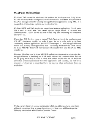
At last step we create invoker to test our command design pattern. Invoker loads
commands.
public class Invoker
{
Command commands[] = new Command[5];
int position;
public Invoker()
{
position = -1;
}
public void setCommand(Command c)
{
if (position < commands.length - 1){
position++;
commands[position] = c;
} else {
for (int loopIndex = 0; loopIndex < commands.length - 2;
loopIndex++){
commands[loopIndex] = commands[loopIndex + 1];
}
commands[commands.length - 1] = c;
}
}
public void run()
{
commands[position].execute();
}
UIU Week 7, CSE 6087 7/29](https://image.slidesharecdn.com/cse-6007fall2012-121003234513-phpapp02/85/Cse-6007-fall2012-88-320.jpg)
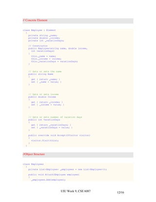
![public void undo()
{
if (position >= 0){
commands[position].undo();
}
position--;
}
}
The testing of the above command design pattern is as follows:
public class TestCommands
{
public static void main(String args[])
{
TestCommands t = new TestCommands();
}
public TestCommands()
{
Invoker invoker = new Invoker();
// Create the receivers
AsiaServer asiaServer = new AsiaServer();
EuroServer euroServer = new EuroServer();
USServer usServer = new USServer();
//Create the commands
ShutDownCommand shutDownAsia = new ShutDownCommand(asiaServer);
RunDiagnosticsCommand runDiagnosticsAsia = new
RunDiagnosticsCommand(asiaServer);
RebootCommand rebootAsia = new RebootCommand(asiaServer);
ShutDownCommand shutDownEuro = new ShutDownCommand(euroServer);
RunDiagnosticsCommand runDiagnosticsEuro = new
RunDiagnosticsCommand(euroServer);
RebootCommand rebootEuro = new RebootCommand(euroServer);
ShutDownCommand shutDownUS = new ShutDownCommand(usServer);
RunDiagnosticsCommand runDiagnosticsUS = new
RunDiagnosticsCommand(usServer);
RebootCommand rebootUS = new RebootCommand(usServer);
invoker.setCommand(shutDownAsia);
invoker.run();
invoker.setCommand(rebootAsia);
invoker.run();
invoker.undo();
invoker.undo();
}
}
UIU Week 7, CSE 6087 8/29](https://image.slidesharecdn.com/cse-6007fall2012-121003234513-phpapp02/85/Cse-6007-fall2012-89-320.jpg)


![return false;
}
public void remove()
{
}
}
• Next coding the branches i.e. division. Division contains leaves. The class is
given below.
public class Division extends Corporate
{
private Corporate[] corporate = new Corporate[100];
private int number = 0;
private String name;
public Division(String n)
{
name = n;
}
public String getName()
{
return name;
}
public void add(Corporate c)
{
corporate[number++] = c;
}
public Iterator iterator()
{
return new DivisionIterator(corporate);
}
public void print()
{
Iterator iterator = iterator();
while (iterator.hasNext()){
Corporate c = (Corporate) iterator.next();
c.print();
}
}
}
• The iterator for leaves is given below.
public class DivisionIterator implements Iterator
{
UIU Week 9, CSE 6087 4/16](https://image.slidesharecdn.com/cse-6007fall2012-121003234513-phpapp02/85/Cse-6007-fall2012-114-320.jpg)
![private Corporate[] corporate;
private int location = 0;
public DivisionIterator(Corporate[] c)
{
corporate = c;
}
public java.lang.Object next()
{
return corporate[location++];
}
public boolean hasNext()
{
if(location < corporate.length && corporate[location]
!= null){
return true;
} else {
return false;
}
}
public void remove()
{
}
}
• Now corporation one which contains the whole hierrachy
public class Corporation extends Corporate
{
private ArrayList corporate = new ArrayList();
private int number = 0;
public Corporation()
{
}
public void add(Corporate c)
{
corporate.add(c);
}
public void print()
{
Iterator iterator = corporate.iterator();
while (iterator.hasNext()){
Corporate c = (Corporate) iterator.next();
c.print();
}
}
}
UIU Week 9, CSE 6087 5/16](https://image.slidesharecdn.com/cse-6007fall2012-121003234513-phpapp02/85/Cse-6007-fall2012-115-320.jpg)
![• The last one is testing the whole. The client program is given below.
public class TestCorporation
{
Corporation corporation;
public static void main(String args[])
{
TestCorporation t = new TestCorporation();
}
public TestCorporation()
{
// Construct the organization
corporation = new Corporation();
Division rnd = new Division("R&D");
rnd.add(new VP("Steve", "R&D"));
rnd.add(new VP("Mike", "R&D"));
rnd.add(new VP("Nancy", "R&D"));
Division sales = new Division("Sales");
sales.add(new VP("Ted", "Sales"));
sales.add(new VP("Bob", "Sales"));
sales.add(new VP("Carol", "Sales"));
sales.add(new VP("Alice", "Sales"));
Division western = new Division("Western Sales");
western.add(new VP("Wally", "Western Sales"));
western.add(new VP("Andre", "Western Sales"));
sales.add(western);
VP vp = new VP("Cary", "At Large");
corporation.add(rnd);
corporation.add(sales);
corporation.add(vp);
// Composite Pattern works here
corporation.print();
}
}
UIU Week 9, CSE 6087 6/16](https://image.slidesharecdn.com/cse-6007fall2012-121003234513-phpapp02/85/Cse-6007-fall2012-116-320.jpg)


![7. Services are thread-safe
The service must be designed so that it can sustain concurrent access from multiple
clients. The service should also be able to handle causality and logical thread re-
entrancy.
Which is SOA and which is not?
• One could argue that web services was the first step on the road to SOA. Is
that statement true? Yes and no. No, in that you can have an SOA solution
without using web services. Yes, in that it is a great beginning to something
much larger.
• A good web service is almost self-describing, providing useful information. We
can hit a web service that gives me stock quotes, or lets me buy or sell
stocks, or tells me how my portfolio is doing. In the case of the book
publisher, I want a web service that tells me information about my order.
These are web services that exhibit SOA traits.
• In contrast, a web service that provides reads as well as writes data to my
database shows no SOA. Now, don’t get me wrong. Those types of web
services have their place and provide great benefits. But they don’t fit in the
SOA realm and don’t conform to the SOA principles as above mentioned.
Difference between WCF and Web service
Features Web Service WCF
It can be hosted in IIS, windows
Hosting It can be hosted in IIS activation service, Self-hosting, Windows
service
[WebService] attribute has to [ServiceContraact] attribute has to be
Programming
be added to the class added to the class
[WebMethod] attribute
[OperationContract] attribute represents
Model represents the method exposed
the method exposed to client
to client
Can be accessed through Can be accessed through HTTP, TCP,
Transports
HTTP, TCP, Custom Named pipes, MSMQ,P2P, Custom
UIU Week 9, CSE 6087 8/24](https://image.slidesharecdn.com/cse-6007fall2012-121003234513-phpapp02/85/Cse-6007-fall2012-134-320.jpg)


![Addresses
In WCF, every service is associated with a unique address. WCF supports the
following transport schemas:
• HTTP
• TCP
• Peer network
• IPC (Inter-Process Communication)
• MSMQ
Addresses always have the following format:
[base address]/[optional URI]
Here are a few sample addresses:
http://localhost:8001
http://localhost:8001/MyService
net.tcp://localhost:8002/MyService
net.msmq://localhost/private/MyQueue
Contracts
Defining and implementing a service contract in C# is given as follows:
[ServiceContract]
interface IMyContract
{
[OperationContract]
string MyMethod(string text);
//Will not be part of the contract
string MyOtherMethod(string text);
}
class MyService : IMyContract
{
public string MyMethod(string text)
{
return "Hello " + text;
}
public string MyOtherMethod(string text)
{
return "Cannot call this method over WCF";
}
}
UIU Week 9, CSE 6087 13/24](https://image.slidesharecdn.com/cse-6007fall2012-121003234513-phpapp02/85/Cse-6007-fall2012-139-320.jpg)

![Endpoints
• Every service is associated with an address that defines where the service is, a
binding that defines how to communicate with the service, and a contract that
defines what the service does. This triumvirate governing the service is easy to
remember as the ABC of the service. WCF formalizes this relationship in the form
of an endpoint. The endpoint is the fusion of the address, contract, and binding.
• Configuring an endpoint administratively requires placing the endpoint details in
the hosting process's config file.
namespace MyNamespace
{
[ServiceContract]
interface IMyContract
{...}
class MyService : IMyContract
{...}
}
The endpoint of the above service is as follows.
<system.serviceModel>
<services>
<service name = "MyNamespace.MyService">
<endpoint
address = "http://localhost:8000/MyService"
binding = "wsHttpBinding"
contract = "MyNamespace.IMyContract"
/>
</service>
</services>
</system.serviceModel>
UIU Week 9, CSE 6087 15/24](https://image.slidesharecdn.com/cse-6007fall2012-121003234513-phpapp02/85/Cse-6007-fall2012-141-320.jpg)

![Use visual studio 2008 for the above project.
Server-side Programming
IUniService.cs
namespace UniService
{
[ServiceContract]
public interface IUniService
{
[OperationContract]
string GetGrade(double marks);
}
}
GradingService.svc
namespace UniService
{
public class GradingService : IUniService
{
public string GetGrade(double marks)
{
if (marks >= 90)
return "A";
else if (marks >= 86)
return "A-";
else if (marks >= 82)
return "B+";
else if (marks >= 78)
return "B";
UIU Week 9, CSE 6087 17/24](https://image.slidesharecdn.com/cse-6007fall2012-121003234513-phpapp02/85/Cse-6007-fall2012-143-320.jpg)


![The format of this address is as follows:
net.msmq://hostname / [private] / queue-name
and the example is:
net.msmq://localhost/msmqshare/bookorder
5. Named Pipe Address
A named pipe is a method for passing information from one computer process to
other processes using a pipe or message holding place that is given a specific
name. The Named Pipe address is formatted as follows:
net.pipe://localhost/myservice
Bindings
A binding specifies how a service is accessible.
1. BasicHttpBinding
Due to the binding's simplicity it enables a higher level of interoperability with
existing web service client and services. It represents bindings that a service can
use to communicate with ASMX-based clients. It aims for clients which do not
have .NET 3.0 installed. The following example illustrates some of the properties
of BasicHttpBinding being configured in a configuration file:
<system.serviceModel>
<bindings>
<basicHttpBinding>
<binding name = “basichttpbind”
closeTimeout = “00:00:30”
openTimeout = “00:00:30”
sendTimeout = “00:00:30”
receiveTimeout = “00:00:30”>
</binding>
</basicHttpBinding>
</bindings>
</system.ServiceModel>
UIU Week 10, CSE 6087 4/16](https://image.slidesharecdn.com/cse-6007fall2012-121003234513-phpapp02/85/Cse-6007-fall2012-154-320.jpg)


![How to use Address and Bindings: an Example
This project is given in lesson-10a.rar.
1. Create a solution WCFService
IServiceClass.cs
namespace WCFService
{
[ServiceContract]
public interface IServiceClass
{
[OperationContract]
string GetText();
[OperationContract]
int MultiplyNumbers(int firstvalue, int secondvalue);
}
}
ServiceClass.cs
namespace WCFService
{
public class ServiceClass : IServiceClass
{
string IServiceClass.GetText()
{
StreamReader sw = new StreamReader(
@"D:MonzurUIU_semesterSummer-2011CSE 6007SmapleWCFPoj
TCP_BindingExampleFileFolderWCFServiceTest.txt");
return sw.ReadLine();
}
int IServiceClass.MultiplyNumbers(int firstvalue,int
secondvalue)
{
return firstvalue * secondvalue;
}
}
}
UIU Week 10, CSE 6087 7/16](https://image.slidesharecdn.com/cse-6007fall2012-121003234513-phpapp02/85/Cse-6007-fall2012-157-320.jpg)


![Contracts
• Contracts in Windows Communication Foundation provide the interoperability
they need to communicate with the client.
• It is through contracts that clients and services agree as to the types of
operations and structures they will use during the period that they are
communicating back and forth.
Three basic contracts are used in WCF.
1. Service Contract
• a service contract defines the operations, or methods, that are available on
the service endpoint and is exposed to the outside world. It also defines the
basic message exchange patterns, such as whether the message behaves in a
request/reply, one-way, or duplex behavior.
•
• A service contract is defined by simply applying the [ServiceContract]
annotation to an interface or class. The following example shows how to
define an interface as a service contract:
[ServiceContract]
public interface IBookOrder
{
//do some stuff
}
• Service operations are specified by applying the [OperationContract]
annotation on the methods of an interface, as illustrated in this example:
[OperationContract]
bool PlaceOrder(string orderdate, string bookisbn);
[OperationContract]
bool CheckOrder(int ordernumber);
UIU Week 10, CSE 6087 14/16](https://image.slidesharecdn.com/cse-6007fall2012-121003234513-phpapp02/85/Cse-6007-fall2012-164-320.jpg)
![• Put these two together to make a complete service contract, as shown here:
[ServiceContract]
public interface IBookOrder
{
[OperationContract]
bool PlaceOrder(string orderdate, string bookisbn);
[OperationContract]
bool CheckOrder(int ordernumber);
}
Lab-1
The example-1 uses TCP binding to read the content of a file and
multiply two numbers. You are expected to provide the options TCP or
Named pipe bindings i.e. two endpoints. The rest is same as before.
UIU Week 10, CSE 6087 15/16](https://image.slidesharecdn.com/cse-6007fall2012-121003234513-phpapp02/85/Cse-6007-fall2012-165-320.jpg)


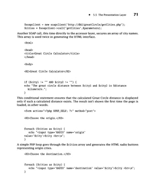
![64 Chapter 5: Designing and Implementing a Multi-Tier Application in PHP «
/ / SreturnArray (an associative array) for returning.
while ($row = $result->fetchRow())
{
$returnArray[$i]=$row[0];
++$i;
}
This loop exists to use MySQL's fetchRowO function against every row in the result object,
thus extracting it. Because we know the result set has only one column (the SQL statement
requested only cityName), we can take the first element of every row array ($row[0]—the
only element) and put it into another array, SreturnArray.
/ / Disconnect from database and return SreturnArray...
$db->disconnect();
return SreturnArray;
}
Having extracted all returned rows, the function terminates the database connection and
returns SreturnArray. Because this function is exposed as a SOAP service, SreturnArray
could be sent out across the network via the SOAP protocol. It's not a problem; SOAP
handles the transmission of arrays without any hassle.
5.3.3 Getting Latitudes and Longitudes from the Database
The other function of the Great Circle application's accessor layer is to get latitude and
longitude of a specified city from the database. This piece of accessor software has to
take a city name as a parameter and use it in extracting coordinate data from the cities
table.
This functionality appears in getLatLong.php, which is listed and commented upon
here:
require_once('nusoap-0.6/nusoap.php');
require_once('dbDetails.php');
// Establish NuSOAP soap_server object
// and register function as Web Service...
Ss = new soap_server;
Ss->register('getLatLong');
Ss->service(SHTTP_RAW_POST_DATA);](https://image.slidesharecdn.com/cse-6007fall2012-121003234513-phpapp02/85/Cse-6007-fall2012-197-320.jpg)

![66 Chapter 5: Designing and Implementing a Multi-Tier Application in PHP •
Slatitude = $row[0];
Slongitude = $row[l];
$returnArray['city'] = $city;
$returnArray['latitude'] = Slatitude;
SreturnArray['longitude'] = Slongitude;
}
This function differs from getCitiesO in that it uses the query results, which comprise
three columns, to create an associative array. The code inside the while loop relies on the
fact that the sequence of the columns in the result set is known—a situation that results
from the explicit listing of column names in the SELECT statement.
/ / Disconnect from database and return SreturnArray...
$db->disconnect();
return SreturnArray;
}
When the work of querying the database and transferring the results to an associative array
is done, the function shuts down the database connection and returns the associative array
containing coordinate information.
5.4 The Business Logic Layer
The business logic layer is where you tackle the problems your program was created to
solve. In the logic layer, classes decide what information they need in order to solve
their assigned problems, request that information from the accessor layer, manipulate
that information as required, and return the ultimate results to the presentation layer for
formatting.
The business logic layer in this application does the spherical geometry—the Great
Circle calculation itself. The calculation program, calcGreatCircle.php, uses an algorithm
that assumes the Earth is perfectly spherical, which it isn't. The calculation is not the point
here, so if you're thinking about using this application as a serious navigation tool, think
again.
In terms of software requirements, calcGreatCircle.php is interesting because it has
to be both a SOAP server and a SOAP client. As a SOAP server, it takes city name pairs from
the presentation layer. As a SOAP client, it forwards those city names to the accessor layer,
getLatLong.php, specifically, in order to retrieve the latitude and longitude of each.
Here are the contents of calcGreatCircle.php, the sole element of the Great Circle
application's business logic layer:](https://image.slidesharecdn.com/cse-6007fall2012-121003234513-phpapp02/85/Cse-6007-fall2012-199-320.jpg)
![5.4 The Business Logic Layer 67
require_once(' nusoap-0.6/nusoap. p h p ' ) ;
/ / Establish NuSOAP soap_server object
//and r e g i s t e r function as Web S e r v i c e . . .
$s = new soap_server;
$s->register('calculateGreatCircle');
$s->service($HTTP_RAW_POST_DATA);
Only the NuSOAP library is imported; there's no need for the database stuff here. The
c a l c u l a t e G r e a t C i r c l e ( ) function is exposed as a SOAP service.
function toRad($degrees) {
// Converts Sdegrees to equivalent value in radians.
Sradians = Sdegrees * (pi()/180);
return Sradians;
}
The function toRadO is a utility function that calculateGreatCircle() makes use of.
It converts a value expressed in degrees into an equivalent value expressed in radians. This
function is not exposed as a SOAP service; it's accessed only by calculateGreatCircle().
function calculateGreatCircle(Scityl, Scity2) {
// Calculates Great Circle distance (in km) between Scityl and Scity2
// Establish Sparameters array and call Web Service to get latitude and
longitude for Scityl...
Sparameters = array('city'=>Scityl);
S soapclient = new soapclient('http://db2/greatCircle/getLatLong.php');
SreturnedArray = Ssoapclient->call('getLatLong',Sparameters);
// Populate simple variables for clarity...
Slatl = SreturnedArray[latitude];
Slongl = SreturnedArray[longitude];
// Establish Sparameters array and call Web Service to get latitude and
longitude for Scity2...
Sparameters = array('city'=>Scity2);](https://image.slidesharecdn.com/cse-6007fall2012-121003234513-phpapp02/85/Cse-6007-fall2012-200-320.jpg)
![68 Chapter 5: Designing and Implementing a Multi-Tier Application in PHP
Ssoapclient = new soapclient('http://db2/greatCircle/getLatLong.php');
SreturnedArray = $soapclient->call('getLatLong',$parameters);
// Populate simple variables for clarity...
$lat2 = $returnedArray[latitude];
$long2 = $returnedArray[longitude];
// Convert degrees to radians
$latl = toRad($latl);
$longl = toRad($longl);
$lat2 = toRad($lat2);
$long2 = toRad($long2);
// Calculate distance...
$theta = $long2 - $longl;
$distance = acos((sin($latl) * sin($lat2)) + (cos($latl) * cos($lat2) *
cos($theta)));
if (Sdistance < 0) {
$distance = $distance + pi();
}
// Multiply by constant to get kilometers...
Sdistance = Sdistance * 6371.2;
return $distance;
}
The rest of calcGreatClrcIe.php has to do with the Great Circle calculation itself, which
isn't remarkable except for its extensive use of PHP's trigonometry functions.
5.5 The Presentation Layer
The presentation layer exists for the purpose of providing a user interface, whether the
user is a machine or a human being. If the user is a human being, the user interface
will likely take the form of an hypertext markup language (HTML) document. They will
likely include text boxes, buttons, and selection lists—all the usual elements we see when
we use our computers. The details of user interface design (how to arrange your pro-
gram's interface elements, how your commands should behave, what sort of feedback](https://image.slidesharecdn.com/cse-6007fall2012-121003234513-phpapp02/85/Cse-6007-fall2012-201-320.jpg)
![• 5.5 The Presentation Layer 69
your users should get, and so on) make up an elaborate field of programming specialty.
They're largely beyond the scope of this book, so we'll deal only with the characteristics
of the user interface that have to do with communicating with the rest of the application.
If the user is a machine, another software application of some kind, our program
should probably generate an extensible markup language (XML) document as output.
The beauty of the multi-tier architecture comes through when you consider that it would
be just as easy to provide XML, rather than HTML, documents at the presentation layer.
With XML results being generated, the application becomes, broadly speaking, more of
a Web service (to be used by other machines rather than by people) than a business appli-
cation. That means someone else could use your whole application as a module in his or
her project.
The presentation layer of the Great Circle application comprises a single page, which
perhaps not ideally, contains a combination of PHP and HTML code. Its "life cycle" has two
parts. First, it displays lists of candidate origin and destination cities, each with a cor-
responding radio button, and a master Submit button at the bottom of the page. That's
shown in Figure 5.2.
When the user chooses cities and clicks the Submit button, the page changes to
include the calculated distance between the two previously selected cities, as depicted
in Figure 5.3.
Here's a commentary on the presentation layer program, greatCircle.php (the name,
which makes no mention of the presentation layer, was chosen because the user may have
to type this filename as part of a URL):
require_once('nusoap-0.6/nusoap.php');
/ / Extract from $_POST array to allow for register_globals being off
$cityl = $_POST['origin'];
$city2 = $_POST['destination'];
Variables $_POST[ ' o r i g i n ' ] and $_POST[destination] correspond to the name attributes
of the two sets of radio buttons in the HTML that appear later in greatCircle.php. When
a form is submitted to this program (it's submitted to itself, a process that's explained
later in this section), the value attribute of the selected radio button from each group is
the value of $_POST['origin'] and $_POST[destination]. Note that it's no longer good
practice to refer to Sorigin and S d e s t i n a t i o n directly, as was reasonable with the older
versions of PHP that shipped with the r e g i s t e r _ g l o b a l s option (in php.ini) on bydefault.
Modern versions of PHP have r e g i s t e r _ g l o b a l s off, so we must approach form contents
via the superglobal $_POST (or $_GET) array. See Chapter 4 for more information on HTTP
POST and HTTP GET operations.
/ / Establish Sparameters array and c a l l Web Service to get distance
$parameters = array(*cityl'=>$cityl, 'city2'=>$city2);
$soapclient = new s o a p c l i e n t ( ' h t t p : / / d b 2 / g r e a t C i r c l e / c a l c G r e a t C i r c l e . p h p ' ) ;](https://image.slidesharecdn.com/cse-6007fall2012-121003234513-phpapp02/85/Cse-6007-fall2012-202-320.jpg)


Cse 6007 fall2012
- 1. United International University (UIU) Dept. of Computer Science & Engineering (CSE) Trimester: Fall 2012 Course Outlines Course: CSE 6007 Course Title: Design and Development Open Multi-tier Application Faculty: Prof.. S M Monzurur Rahman ([email protected]) Assessment: Component Marks(%) Attendance 5 Continuous Assessment - Class Test 10 Continuous Assessment - Project 15 Midterm 30 Final 40 Total 100 Reference Book 1. Design Patterns, by Erich Gamma, Richard Helm, Ralph Johnson, John Vlissides 2. Patterns of Enterprise Application Architecture, By Martin Fowler 3. WCF 4.0 Multi-tier Services Development with LINQ to Entities By Mike Liu Lecture 1 • Introduction to Design Pattern • The strategy Design Pattern Lecture 2 • Value Object pattern. • The Decorator Design Pattern • The Factory Design Pattern Lecture 3 • The Observer Design Pattern • The Singleton Design Pattern • The Adapter Design Pattern Lecture 4 • **** Class Test • Registry design pattern 1
- 2. • Dependency Injection Pattern Lecture 5 • The Facade Design Pattern • The Template Design Pattern • Model-View-Controller Lecture 6 • Mid-Exam Lecture 7 • Enterprise Pattern • SOAP • Open and Close Multi-tier Lecture 8 • The Composite Design Pattern • The Visitor Design Pattern • The Proxy Design Pattern Lecture 9 • SOA Design pattern • SOA in .NET • Web services • SOAP • WCF: Windows Communication Foundation Lecture 10 • **** Class Test • Implementing a Basic WCF Service • Creating a client to consume the WCF service Lecture 11 • MVC3-Rajor Lecture 12 • Project Demonstration • Review Lecture 13 • Final Exam END OF SEMESTER!!! ENJOY!!! 2
- 3. United International University Trimester: Fall 20012 Course: CSE 6007 Course Title: Design and Development Open Multi-tier Application Faculty: Prof. Dr. Monzurur Rahman ([email protected]) Week 1: Introduction and The strategy Design Pattern Design Pattern A design pattern is: • a standard solution to a common programming problem. Some problems come up over and over in object-oriented programming. A design pattern represents a codified solution to a problem, an idiom that you can apply when you encounter it again. • a shorthand for communicating design concepts. Design patterns provide a vocabulary for sharing software designs with other programmers, both verbally and in documentation and specifications. Rather than a wordy description like “this class steps through a collection and returns one element at a time”, you can just say “this class is an iterator.” • a particular shape of object diagram, object model, or module dependency diagram. Many patterns reveal themselves this way, often by reducing the degree of coupling between components to make the design more amenable to change. • The bible for design patterns is the so-called “Gang of Four” book, Design Patterns: Elements of Reusable Object-Oriented Software, by Gamma, Helm, Johnson, and Vlissides, which is a recommended course text. UIU Week 1, CSE 6087 1/23
- 4. Example# 1 • Lets we have an old object and interface which takes old object • After some time, interface has been changed and issue is how to handle the change. • Design pattern gives the solution to this problem using adaptor pattern. UIU Week 1, CSE 6087 2/23
- 5. Example# 2 • Lets you are designing a web site which has the following pages. • There are a lot of interactions between pages and which makes the programming complex. In that case a mediator design pattern provides a good solution. UIU Week 1, CSE 6087 3/23
- 6. Kinds of Design Patterns 1. Architectural Patterns An architectural pattern expresses a fundamental structural organization or schema for software systems. It provides a set of predefined subsystems, specifies their responsibilities, and includes rules and guidelines for organizing the relationships between them. Example: Distributed Event-driven Frame-based Layered MVC Tier – Open / Close 2. Creational Patterns • Creational design patterns are design patterns that deal with object creation mechanisms, trying to create objects in a manner suitable to the situation. • .Example: Factory Prototype Singleton pattern Builder pattern 3. Structural patterns • Structural design patterns are design patterns that ease the design by identifying a simple way to realize relationships between entities. • Example: Adapter UIU Week 1, CSE 6087 4/23
- 7. Bridge Proxy Aggregate pattern 4. Behavioral patterns • Behavioral design patterns are design patterns that identify common communication patterns between objects and realize these patterns. By doing so, these patterns increase flexibility in carrying out this communication. • .Example: Chain of responsibility Mediator Visitor Riehle and Zullighoven make similar distinctions, but seem to partition the different kinds of patterns among analysis, design, and implementation. They define the terms conceptual patterns, design patterns, and programming patterns as follows: 1. Conceptual Patterns A conceptual pattern is a pattern whose form is described by means of terms and concepts from an application domain. 2. Design Patterns A design pattern is a pattern whose form is described by means of software design constructs, for example objects, classes, inheritance, aggregation and use- relationship. 3. Programming Patterns A programming pattern is a pattern whose form is described by means of programming language constructs Qualities of a Pattern A well written pattern should exhibit several desirable qualities and they are: UIU Week 1, CSE 6087 5/23
- 8. • Encapsulation and Abstraction Each pattern encapsulates a well-defined problem and its solution in a particular domain. • Openness and Variability Each pattern should be open for extension or parametrization by other patterns so that they may work together to solve a larger problem. • Generativity and Composability Each pattern, once applied, generates a resulting context which matches the initial context of one or more other patterns in a pattern language. These subsequent patterns may then be applied to progress further toward the final goal of generating a "whole" or complete overall solution. • Equilibrium Each pattern must realize some kind of balance among its forces and constraints. This may be due to one or more invariants or heuristics that are used to minimize conflict within the solution space. The invariants often typify an underlying problem solving principle or philosophy for the particular domain, and provide a rationale for each step/rule in the pattern. Patterns and Algorithms • Algorithms and data structures may be employed in the implementation of one or more patterns, but algorithms and data structures generally solve more fine- grained computational problems like sorting and searching. • Patterns are typically concerned with broader architectural issues that have larger- scale effects. The design patterns in [GoF] address people and development issues like maintainability, reusability, communicating commonality and encapsulation variation. These are issues that matter to the people who need to create and evolve/grow these software systems over time. UIU Week 1, CSE 6087 6/23
- 9. • Algorithms and data structures are usually concerned almost exclusively with optimizing space or time or some other aspect of computational complexity and resource consumption. Patterns and Frameworks One thing closely related to design patterns and object-orientation is a software framework. • A framework supplies the infrastructure and mechanisms that execute a policy for interaction between abstract components with open implementations. • A software framework is a reusable mini-architecture that provides the generic structure and behavior for a family of software abstractions, along with a context of memes/metaphors which specifies their collaboration and use within a given domain. • A framework is a set of cooperating classes that make up a reusable design for a specific class of software. A framework provides architectural guidance by partitioning the design into abstract classes and defining their responsibilities and collaborations. A developer customizes a framework to a particular application by subclassing and composing instances of framework classes. Example – MVC framework There are three major components of MVC: • Model: Encapsulates core data and logic. Model is often related with the business logic of the application. It knows all the data that needs to be displayed. It is always isolated from the User Interface (UI) and the way data needs to be displayed. • View: It is the UI part of the application. It uses read-only methods of the model and queries data to display them to the end users. It may be a window GUI or a UIU Week 1, CSE 6087 7/23
- 10. HTML page. View encapsulates the presentation of the data, there can be many views of the common data • Controller: It acts as a interacting glue between models and views. It accepts input from the user and makes request from the model for the data to produce a new view. UIU Week 1, CSE 6087 8/23
- 11. The [GoF] book describes the major differences between design patterns and frameworks as follows: • Design patterns are more abstract than frameworks. Frameworks can be embodied in code, but only examples of patterns can be embodied in code. A strength of frameworks is that they can be written down in programming languages and not only studied but executed and reused directly. In contrast, design patterns have to be implemented each time they are used. Design patterns also explain the intent, trade-offs, and consequences of a design. • Design patterns are smaller architectural elements than frameworks. A typical framework contains several design patterns but the reverse is never true. • Design patterns are less specialized than frameworks. Frameworks always have a particular application domain. In constrast, design patterns can be used in nearly any kind of application. While more specialized design patterns are certainly possible, even these wouldn't dictate an application architecture. UIU Week 1, CSE 6087 9/23
- 12. Design Principles • Encapsulate aspects of your application that vary • Program to interfaces, not implementations • Favor composition over inheritance • Classes should be open for extension but closed for modification • Strive for loosely coupled designs between objects that interact • Depend upon abstraction, not concrete classes Pattern Catalogs A pattern catalog is a collection of related patterns (perhaps only loosely or informally related). It typically subdivides the patterns into at least a small number of broad categories and may include some amount of cross referencing between patterns. Design Anti-Patterns • A design anti-pattern is an example of design that initially appeared to be a good idea, but later turned out to be a bad one. • Anti-patterns are examples of bad design and bad coding practice. Examples of object-oriented anti-patterns: a) Creating massive classes with a huge number of methods. b) Too many utility classes that perform too many operations. A utility class is one that has only static methods, no state and which performs operations on objects that are passed in. • Significance of Design Anti-Patterns Anti-patterns are useful for the same reason that patterns are useful, anti-patterns provide a way to document and spot bad design and to (hopefully) provide remedies. It's a good idea to know about anti-patterns so that your code doesn't use any, so that they can be recognised the next time code is maintained and so that their impact can be appreciated at the next code review. They should be identified as early as possible in the software life- cycle as it's easier to re-design code than unpick its implementation. UIU Week 1, CSE 6087 10/23
- 13. Criticisms of Patterns • Some have criticized design patterns, pointing out that they don't provide reuse nor do they differ significantly from other abstractions. The purpose of design patterns is to capture commonality at the design level. Patterns can be reused once implemented; however, as soon as the design is implemented, it has become specific to the particular language and environment in which it will be deployed. The implementation of a persistence layer pattern would be radically different on a handheld device compared to one for a server environment. The pattern for these two environments will have some elements in common and this commonality can be reused at the design level. The pattern can then be decomposed and refined, one for each environment, and the individual patterns can be reused and implemented. The two patterns and the common part can then be made publically available from the Portland Pattern Repository. Patterns and their implementations compliment each other, however, one isn't a replacement for the other and patterns are design-level entities. • I've often thought design patterns were clever, but a toy when compared to reality. I think in real systems we use thousands of different patterns and morph them and hybridize them as we go. Building real software out of a few toy patterns is like building a Lamborghini out of lego. I think what we really need then are ways to dynamically discover the patterns we care about at a given moment, I think of it as "data mining the code". 1. Strategy Pattern • Behavioral Pattern • Encapsulates an algorithm inside a class. • Defines a family of interchangeable encapsulated algorithms that receives the same input type and provides the same output type in different manners that can be determined in run-time. UIU Week 1, CSE 6087 11/23
- 14. Why do we need? Consider the following basic design: • Carry() is defined in base class and run() is overridden in the derived classes as required. • Suddenly you recognise that, as this is for worldwide cars, there are some cars, which go for race. • Only change required is to add a race() method in the base class so some cars can go for the race. • User starts the Demo with the above change , Some thing went horribly wrong: "Taxi's started racing" "RaceCar's started carrying passengers" • Now code needs to be modified. Modify Taxi Class - Race() to do nothing Modify RaceCar Class -Carry() to do nothing • But consider about ToyCar they do not race nor they do not Carry. Create the ToyCar Class - Race() to do nothing UIU Week 1, CSE 6087 12/23
- 15. -Carry() to do nothing • As long as new type of car's come, the more modification is required in base class and derived classes (need to override code). This is the problem to maintain the code. To solve this problem Strategy Design Patterns comes as a solution. Solution • In order to solve the above problem we separate car class than car behavior i.e. Separate the algorithm code from the class code. • We use "Program to an interface, not an implementation” The interfaces can be designed as follows: UIU Week 1, CSE 6087 13/23
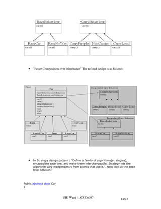
- 16. • "Favor Composition over inheritance" The refined design is as follows: • In Strategy design pattern : "Define a family of algorithms(strategies), encapsulate each one, and make them interchangeable. Strategy lets the algorithm vary independently from clients that use it.". Now look at the code level solution: Public abstract class Car { UIU Week 1, CSE 6087 14/23
- 17. CarryBehaviour carryBehaviour; RaceBehaviour raceBehaviour; public Car() { } public abstract void run(); public void race() { raceBehaviour.race(); } public void carry() { carryBehaviour.carry(); } public void setraceBehaviour(RaceBehaviour rb) { raceBehaviour = rb; } public void setcarryBehaviour(CarryBehaviour cb) { carryBehaviour = cb; } } UIU Week 1, CSE 6087 15/23
- 18. RaceBehaviour (Interface), RaceCar (Class) & RaceNoWay (Class): public interface RaceBehaviour { public void race(); } public class RaceCar implements RaceBehaviour { public void race() { system.out.println("I am racing"); } } public class RaceNoWay implements RaceBehaviour { public void race() { system.out.println("I can't race"); } } CarBehaviour (Interface), CarryPeople (Class) , NonCarrier (Class) & CarryLoad (Class): public interface CarryBehaviour { public void carry(); } public class CarryPeople implements CarryBehaviour { public void carry() { system.out.println("I can carry only people"); } } public class NonCarrier implements CarryBehaviour { public void carry() { system.out.println("I can't carry"); } } UIU Week 1, CSE 6087 16/23
- 19. public class CarryLoad implements CarryBehaviour { public void carry() { system.out.println("I can carry only Load"); } } Car Class Public class Taxi extends Car { public Taxi() { carryBehaviour = new CarryPeople(); raceBehaviour = new RaceNoWay(); } public void run() { System.out.println("Running a Taxi"); } } Jeep Class Public class Jeep extends Car { public Jeep () { carryBehaviour = new CarryLoad(); raceBehaviour = new RaceNoWay(); } public void run() { System.out.println("Running a Jeep"); } } UIU Week 1, CSE 6087 17/23
- 20. RaceCar Class Public class RaceCar extends Car { public RaceCar () { carryBehaviour = new NonCarrier(); raceBehaviour = new RaceCar(); } public void run() { System.out.println("Going for Race"); } } ToyCar Class Public class ToyCar extends Car { public ToyCar () { carryBehaviour = new NonCarrier(); raceBehaviour = new RaceNoWay(); } public void run() { System.out.println("Play with ToyCar "); } } RentalCar Class Public class RentalCar extends Car { public RentalCar () { carryBehaviour = new CarryPeople(); raceBehaviour = new RaceNoWay(); } public void run() { System.out.println("I am Rented Car"); } } UIU Week 1, CSE 6087 18/23
- 21. Small Demo Public class WorldCarSimulator { public static void main(string[] args) { Car Ferrari = new RaceCar(); Ferrari.carry(); Ferrari.race(); Ferrari.run(); Car RoadRunnerTaxi = new Taxi(); RoadRunnerTaxi.carry(); RoadRunnerTaxi.race(); //Changing the behaviour dynamically RoadRunnerTaxi.setraceBehaviour(new RaceBehaviour()); RoadRunnerTaxi.race(); } } • When new thing comes we change outside of the class i.e. when new algorithm comes (behavior), we need to implement that new behavior in a new interface not in class level and that behavior can set dynamically using set method. • Any class change their behavior outside of the class e.g. //Changing the behaviour dynamically RoadRunnerTaxi.setraceBehaviour(new RaceBehaviour()); RoadRunnerTaxi.race(); UIU Week 1, CSE 6087 19/23
- 22. Lab Work (C# or Java): The problem ('design smell') associated with this approach is simply the way we are placing the implementation of the actions Eat() and MakeNoise() inside the concrete classes. This doesn't exactly lead to a maintainable design. For example, suppose we want to extend our animal kingdom by introducing an AllyCat class. An AllyCat might have different implementations of Eat() (eating out of the trash), but still have the same kind of MakeNoise() (moew) implementation. You might think, "well, we can just derive from the concrete class Cat, and override the Eat() method with our own AllyCat.Eat() implementation" and you're right, you can. However, extending behavior through hierarchal inheritance should be avoided. Not only that, designs like this can lead to duplicate code. Instead, you should compose classes with isolated algorithm implementations. The goal is to separate varying-code from non-varying code. A quick way to identify non-varying code aspects of your classes is through "has-a" relationships. A Dog "has-a" distinct eating behavior, a Cat "has-a" distinct eating behavior, an AllyCat "has-a" distinct eating behavior, so on and so forth... From our classes and implementation, we have noise behaviors and eating behaviors. Provide a better solution for the above problem. You must provide the followings in your answer. a.) UML for your solution. b.) Java/C# codes for the solution. The Solution The solution to basic problems is to implement a Strategy pattern. Consider the following architecture: UIU Week 1, CSE 6087 20/23
- 23. And taking a peek in some of the Cat, Ally Cat and Dog code: UIU Week 1, CSE 6087 21/23
- 24. UIU Week 1, CSE 6087 22/23
- 25. All that we have done with this new architecture is delegate the "making noise" and "eating" to behavioral classes that specifically handle the task. We have delegated control to the behavioral classes. This is a much better extensible and coherent design and often leads itself to better to code reuse. Whenever we create classes that are composed of behavioral actions, we call these compositions. Classes such as Dog, Cat, and AllyCat are compositions of behaviors and gain their behavior through composition, not inheritance. Inheritance (like the previous architecture) can lead to unintended consequences when fiddling with the superclass and is more prone to breaking existing code. *************** End of Week 1 ************** UIU Week 1, CSE 6087 23/23
- 26. United International University Trimester: Fall 2012 Course: CSE 6007 Course Title: Design and Development Open Multi-tier Application Faculty: Prof. Dr. Monzurur Rahman ([email protected]) Week 1: Decorator and Factory Design Pattern 2. Decorator Design Pattern • Structural Pattern • Also known as wrapper. • The Decorator Pattern is used for adding additional functionality to a particular object as opposed to a class of objects. It is easy to add functionality to an entire class of objects by subclassing an object, but it is impossible to extend a single object this way. With the Decorator Pattern, you can add functionality to a single object and leave others like it unmodified. Example • Consider you have a following computer class with a description method: UIU Week 1, CSE 6087 1/19
- 27. • After some time you need to add to the description method a disk: UIU Week 1, CSE 6087 2/19
- 28. • You need again to modify the computer class again as follow: • In this way if you need again and again modification to your class then it is difficult to manage since you need to touch the actual class again and again. • To solve the above problem, Decorator pattern comes as a rescue. The design pattern suggests you to create a wrapper class and place the instance of the class to the wrapper class and wrapper class allow you to add new functionality i.e. changing the description method. In this way you do not need to modify the computer class. UIU Week 1, CSE 6087 3/19
- 29. Solution In order to solve the above problem you can design the classes as follows: • Here Monitor description method calls Disk description method and Disk description method in turn call Computer method. • How to code the above Decorator design pattern. o Computer class which has a minimal description UIU Week 1, CSE 6087 4/19
- 30. o We need a basis of Decorator class which is the abstract class as well as the derived class from the main Computer class. o When Disk come to the table then we can design Disk decorator as follows: UIU Week 1, CSE 6087 5/19
- 31. o Similarly if you need another Decorator e.g. CD then you can design that as follows: o Similarly if you need another Decorator e.g. Monitor then you can design that as follows. Do not forget that in the constructor you can pass CD object for Computer c parameter since CD is itself a Computer type. UIU Week 1, CSE 6087 6/19
- 32. o The following way you can use the decorator patterns in the claient program. o The output will be – You are getting a computer and a disk and a monitor and a CD and a CD • The idea behind a decorator pattern is that you can customize your objects by adding multiple wrappers over and over again even the same wrapper twice or more times. • So using Decorator pattern you can customize your object each time using a wrapper without modifying your codes. UIU Week 1, CSE 6087 7/19
- 33. Decorator Applicability • When you need to add responsibilities to individual objects – dynamically and transparently, that is, without affecting other objects – responsibilities that can be withdrawn • when extension by subclassing is not practical – large number of independent extensions are possible and would produce an explosion of subclasses to support every combination – a class definition may be hidden or otherwise unavailable for subclassing Decorator Advantages • Provide an alternative to subclassing. • Responsibilities can be added / removed at run-time by attaching and detaching them • Providing different Decorator classes for a specific Component class lets you mix and match responsibilities • Easy to add a property twice • Pay-as-you-go approach o don't bloat, but extend using fine-grained Decorator classes • Functionality can be composed from simple pieces o thus, an application does not need to pay for features it doesn't use • A fine-grained Decorator hierarchy is easy to extend Decorator Disadvantages • Lots of Little Objects UIU Week 1, CSE 6087 8/19
- 34. o a design that uses Decorator often results in systems o composed of lots of little objects that all look alike o objects differ only in the way they are interconnected, not in their class or in the value of their variables o these systems are easy to customise by those who understand them, they can be hard to learn and debug Factory Design Pattern • Creational Pattern - Provide an interface for creating families of related or dependent objects without specifying their concrete classes. • In OOP, the most common way to create an object is with the new operator, the language construct provided to do just that. But in some cases, new can be problematic. For instance, the creation of many kind of objects requires a series of steps: i) you may need to compute or fetch the object’s initial settings; ii) you might have to choose which of many sub classes to instantiate; iii) or perhaps you have to create a batch of other helper objects before you can create the object you need. In those cases, new is a “process” more than an operation—a cog (component) in a bigger machine. • In Factory Pattern we have the Problem : How can you create such “complex” objects easily and conveniently—without cut-and-paste programming? • The Solution to the above answer- Create a “factory”—a function or a class method— to “manufacture” new objects. Example • Consider a situation where we need a database connection depending on the user’s choice: UIU Week 1, CSE 6087 9/19
- 35. • In one way you can solve the above problem using the following function: • In the above, OracleConnection, SqlServerConnection etc. need to be same class as Connection which Factory Design Pattern Provides. Solution from Factory Pattern • You need a factory pattern to make the better solution for the above problem. • In the Factory Pattern, a factory method defines what functions must be available in the non-abstract or concrete factory. These functions must be able to create objects that are extensions of a specific class. Which exact subclass is created will depend on the value of a parameter passed to the function. • The first version of the Factory class is as follows, The CreateConnection() is called creational method. We need to make the Connection abstract class in order to support CreateConnection() method of Factory Design Pattern UIU Week 1, CSE 6087 10/19
- 36. • The above Factory class is used as follows: • Now have a look how Factory Design Pattern provides the solution. o Step 1: Abstract class of the class that Factory creates o Step 2: All derived classes of the abstract class. UIU Week 1, CSE 6087 11/19
- 37. o Step 3: The following way you can test the above factory design pattern. UIU Week 1, CSE 6087 12/19
- 38. • So the idea here is that the code which changes a lot when design changes (in our case CreateConnection()), extract that code and put into a Factory class and that Factory is responsible to create objects. 4. The Value Object Pattern . • The intent of this pattern is to provide the way to implement data-types as immutable classes so that their instances can be handled like built-in values. It is architectural pattern. • A value object is a small simple object, like a money or date range, whose equality is not based on identity. • You can have multiple copies of an object that represents the date 16 Jan 1998. Any of these copies will be equal to each other. For a small object such as this, it is often easier to create new ones and move them around rather than rely on a single object to represent the date. • A reference object is an object whose equality is based on its identity. Reference objects are big in size e.g. customer, order etc. • A general heuristic is that value objects should be entirely immutable. If you want to change a value object you should replace the object with a new one and not be UIU Week 1, CSE 6087 13/19
- 39. allowed to update the values of the value object itself - updatable value objects lead to aliasing problems. • In n-tier software architecture value object pattern is applied when data is transferred from database to VO (value object tier). Example Consider a tool box class in php which carries only nails. //ToolBox.php class ToolBox { private $_nails; public function getNails() { return $this->_nails; } public function setNails(Nails $nails) { $this->_nails = $nails; } } //Nails.php class Nails { private $_quantity; public function __construct($quantity) { $this->_quantity = (int) $quantity; } UIU Week 1, CSE 6087 14/19
- 40. public function add(Nails $nails) { $this->_quantity += $nails->count(); } public function count() { return $this->_quantity; } private function __toString() { return (string) $this->_quantity; } } //testtoolBox.php $myToolBox = new ToolBox; $yourToolBox = new ToolBox; //Using twenty Nails $twentyNails = new Nails(20); //Start out with equal number of nails. $myToolBox->setNails($twentyNails); $yourToolBox->setNails($twentyNails); //Here's another 100 nails. $yourToolBox->getNails()->add(new Nails(100)); echo "Your nails: {$yourToolBox->getNails()}<br/>"; echo "My nails: {$myToolBox->getNails()}<br/>"; You probably already noticed that problem is that we are both using the same Nails object. In this case the problem may be easy to spot and avoid, but as your application becomes bigger, preventing this type of mishap can save you a huge headache. Another mayor benefit of using Value Objects is they enable you to encapsulate type-specific operations. Martin Fowler does a great job at demonstrating this with his Money pattern, which encapsulates the handling of rounding currency. UIU Week 1, CSE 6087 15/19
- 41. The key to creating Value Objects is making them immutable. Because Value Objects’ equality don’t depend on their identity, simply creating a new object when the value changes, accomplishes this using the following code: public function add(Nails $nails) { return new Nails($this->_quantity + $nails->count()); } //Here's another 100 nails. $yourToolBox->setNails( $yourToolBox->getNails()->add(new Nails(100)) ); Lab Exercise • Given the following code, complete the code for a BoatFactory class so it can be used to create big and small boat objects: public interface Boat { int maxCapacity; int topSpeed( ) } class CruiseShip implements Boat { // big boat int topSpeed( ) { return 20; } } class SpeedBoat implements Boat { // small boat int topSpeed( ) { return 40; } } Boat myBigBoat = BoatFactory. Boat mySmallBoat = BoatFactory.create(“small”); public class BoatFactory { static Boat create(String s) { // your code here if (s.equals(“big”)) return new CruiseShip( ); UIU Week 1, CSE 6087 16/19
- 42. else if (s.equals(“small”)) return new SpeedBoat( ); else return null; // error } } • Using the same code, use the Decorator design pattern to i. Add a BoatDecorator class implementing the Boat interface public class BoatDecorator implements Boat { Boat b; BoatDecorator (Boat b) { this.b = b; } int topSpeed( ) { return b.topSpeed( ); } } ii. Create two BoatDecorators withBarnacle( ) and withTurboEngine( ) that change the result returned by topSpeed( ) by –1 and +10, respectively public class withBarnacle( ) extends BoatDecorator { int topSpeed( ) { return b.topSpeed( ) - 1; } } public class withTurboEngine( ) extends BoatDecorator { int topSpeed( ) { return b.topSpeed( ) + 10; } } Design Problem – Home work Background You are working as part of team which is tasked with designing a security package. The package is to be used as part of a university system to control access to system services. The access control policy is based on the role a particular user plays. There are three roles: Lecturer, Student, and Administrator. Table 1 presents the access rights for each role. Administrator Student Lecturer Install software * Access network * * * Submit coursework solution * Publish coursework problem * UIU Week 1, CSE 6087 17/19
- 43. Table 1 Access privileges A member of your team has proposed an initial design which is shown in Figure 1. With this design, the abstract superclass Operator is intended to be sub-classed with concrete classes representing particular roles. The Operator class provides a default implementation of the isAuthorizedTo() method which simply returns false. The concrete subclasses override this method and depending on the String argument value, return true or false indicating whether instances of the class have permission to do what is described by the String argument. For example, calling isAuthorisedTo() with the argument “install software” on an Administrator instance would return true; calling the method with the same argument on a Student or Lecturer object would return false. Figure 1 Initial design The proposed design, however, suffers from a fundamental weakness. Within the University, a single individual may play several roles. For example, one person might play the Lecturer role and teach undergraduate students. The same person might also be studying part time for a postgraduate degree. In this case, the person will require access rights for both publishing coursework and submitting coursework. With the existing design, a person can only be represented by an instance of one of the three concrete subclasses and is therefore constrained to play a single role. You raise this problem with your team. Another member responds and points out that the problem is easily solved by creating additional subclasses to cater for all the combinations of roles. Specifically, this means defining 3 additional subclasses: LecturerAndStudent, LecturerAndAdministrator, and StudentAndAdministrator. To cater for an individual playing all three roles, a further subclass LecturerAndStudentAndAdministrator would be required. You think about this suggestion for a moment and it doesn’t take you long to see that it’s unattractive. First, it would be error-prone to maintain since if the access rights change for one role, you will have to edit the source files for four classes. For example, adding a new privilege for students, such as allowing them access to file sharing services (likely to be used for sharing music files!) would involve editing the Student, LecturerAndStudent, UIU Week 1, CSE 6087 18/19
- 44. StudentAndAdministratorand LecturerAndStudentAndAdministrator classes. It then occurs to you that the problem would be exacerbated if at a later date you wanted to introduce a new role, such as Secretary. To cater for all possible combinations now would require many more subclasses. And what if further new roles needed to be accommodated after that? Clearly the exponential growth in the number of concrete subclasses is unmanageable. You air your thoughts to your team members. They are impressed by your analysis but look to you for a solution. You quickly consider each of the design patterns you know about, but none of them seem to tackle this seemingly generic problem. A brief search on the Internet using Google with the terms “subclass explosion” and “design pattern” returns a host of links which have in common the Decorator design pattern. The Decorator pattern looks promising … The task Investigate the Decorator design pattern and apply it to develop an alternative design to the access control problem. Your design should address the problems inherent in the original design. The exam question will assess your understanding and application of the pattern and thus requires that you do the necessary preparatory work prior to the exam. *************** End of Week 2 ************** UIU Week 1, CSE 6087 19/19
- 45. United International University Trimester: Fall 2012 Course: CSE 6007 Course Title: Design and Development Open Multi-tier Application Faculty: Prof.. S M Monzurur Rahman ([email protected]) Week 3: The Observer Design Pattern, The Singleton Design Pattern, The Adapter Design Pattern 5. The Observer Design Pattern • Behavioral Pattern – The problem deals with “How can you alert (potentially) many objects when a certain object’s state changes? Is there a scheme that’s dynamic—one that allows interconnections to come and go as a script executes? • The observer pattern is a software design pattern in which an object (called the subject object) maintains a list of its dependents (called observers) and notifies them automatically of any state changes, usually by calling one of their methods. It is mainly used to implement distributed event handling systems. Example • The Observer pattern defines an one-to-many dependency between a subject object and any number of observer objects so that when the subject object changes state, all its observer objects are notified and updated automatically. • The Observer pattern essentially allows an unlimited number of objects to observe or listen to events in the observed object (or subject) by registering themselves. After observers are registered to an event, the subject will notify them when the event is fired. • The subject handles this by storing an observer collection and iterating through it when the event occurs in order to notify each observer. • Observer Pattern registers observers with a subject. UIU Week 3, CSE 6087 1/15
- 46. • You might have multiple observers. Subject must keep a list of registered observers and when event occurs it fires (provides notification) all registered observers. • Unregister also possible when we do not need any observer. UIU Week 3, CSE 6087 2/15
- 47. UML class diagram The following is class diagram of an observer pattern (Kremer 1998): Subject Knows it observers Has any number of observer Provides an interface to attach and detaching observer object at run time Observer Provides an update interface to receive signal from subject ConcreteSubject Store subject state interested by observer Send notification to it's observer ConcreteObserver • Maintain reference to a ConcreteSubject object • Maintain observer state • Implement update operation UIU Week 3, CSE 6087 3/15
- 48. 6. The Adaptor Design Pattern • Structural Pattern • Adapters are used to enable objects with different interfaces to communicate with each other. • Convert the interface of a class into another interface clients expect. It is useful when we upgrade system • Lets you have an interface class which fits in with a back end class. • After some time, management upgrades the system and now the back end object takes Acme object instead of Ace object. • You can see from the above figure that after upgrade Ace object is not able to plug into Backend object any more. • So what do you do - you put an adaptor class in between interface and back end. The adaptor helps interface to communicate with back end class i.e. adaptor adapts one object to another receptacle object. This strategy is called adaptor design pattern. UIU Week 3, CSE 6087 4/15
- 49. Example • Lets we have an example of the adaptor design pattern as follows. • We need an adaptor because Acme object which fits in with back end and Acme’s object’s setFirstName and setLastName is supposed to be setName. Similarly, Acme’s object’s getFirstName and getLastName is supposed to be getName. So, we need an adaptor or converter to convert Ace object to Acme Object. • In order to code the above we first code AceInterface and AceClassas follows. AceClass is based on AceInterface. UIU Week 3, CSE 6087 5/15
- 50. • Next we code AcmeInterface and AcmeClassas follows. AcmeClass is based on AcmeInterface. UIU Week 3, CSE 6087 6/15
- 51. • Next we need to code AceToAcmeAdaptor and the code is as follows. The construct of such class is as follows. Not that it accepts AceClass object in the constructor and through adaptor it connects to AcmeClass. • The code for such adaptor is UIU Week 3, CSE 6087 7/15
- 52. • Now, we are going to do test the adaptor class. This is done through a test program and it is given as follows. • The output of the above test program is as follows: UIU Week 3, CSE 6087 8/15
- 53. 7. The Singleton Design Pattern • Creational Pattern- Ensure a class only has one instance, and provide a global point of access to it. • Sometimes we want just a single instance of a class to exist in the system. For example, we want just one window manager. And we want to ensure that additional instances of the class cannot be created. Example • Normally when you have a class and you create many instances of it then you get many objects e.g., • But in the case of singleton design pattern we get one instantiated object for many calls of getInstance() method instead of new e.g., • Example of Singleton Design pattern is implemented in the following database class. Note that it private constructor. Only getInstance() method is used to create single instance of the class. UIU Week 3, CSE 6087 9/15
- 54. public class Database { private static Database singleObject; private int record; private String name; private Database(String n) // Note private { name = n; record = 0; } public static Database getInstance(String n) // instantiation { if (singleObject == null){ singleObject = new Database(n); } return singleObject; } public void editRecord(String operation) { System.out.println("Performing a " + operation + " operation on record " + record + " in database " + name); } public String getName() { return name; } } • The testing of the singleton pattern is as follows: public class TestSingleton { public static void main(String args[]) { Database database; database = Database.getInstance("products"); System.out.println("This is the " + database.getName() + " databse."); database = Database.getInstance("employees"); System.out.println("This is the " + database.getName() + " databse."); } } UIU Week 3, CSE 6087 10/15
- 55. • Output. Note that we did not get employees database here because of single instantiation. Singleton and multi-threading • What if two threads concurrently invoke the instance() method? Any problems? • When more than one threads pass through the get instance method of the single pattern Database class then both thread see singleObject==null and both of them create Database object and which is not desirable. • To avoid concurrency problem we should redesign the following database class as follows: public class DatabaseSynchronized { private static DatabaseSynchronized singleObject; private int record; private String name; private DatabaseSynchronized(String n) { name = n; record = 0; } UIU Week 3, CSE 6087 11/15
- 56. public static synchronized DatabaseSynchronized getInstance(String n) { if (singleObject == null){ singleObject = new DatabaseSynchronized(n); } return singleObject; } public void editRecord(String operation) { System.out.println("Performing a " + operation + " operation on record " + record + " in database " + name); } public String getName() { return name; } } • The following class can be used to create the Singleton thread. public class TestSingletonSynchronized implements Runnable { Thread thread; public static void main(String args[]) { TestSingletonSynchronized t = new TestSingletonSynchronized(); } public TestSingletonSynchronized() { DatabaseSynchronized database; database = DatabaseSynchronized.getInstance("products"); thread = new Thread(this, "second"); thread.start(); System.out.println("This is the " + database.getName() + " database."); } public void run() { DatabaseSynchronized database = DatabaseSynchronized.getInstance("employees"); System.out.println("This is the " + database.getName() + " database."); } } UIU Week 3, CSE 6087 12/15
- 57. Lab Practice The code below shows a user list that sends out a message when users are added. This list is watched by a logging observer that puts out a message when a user is added. You are supposed to run this program in the lab and understand observer patter (Do it in C#). Observer.php <?php interface IObserver { function onChanged($sender, $args); } interface IObservable { function addObserver($observer); } class UserList implements IObservable { private $_observers = array(); public function addCustomer($name) { foreach( $this->_observers as $obs ) $obs->onChanged( $this, $name ); } public function addObserver( $observer ) { $this->_observers []= $observer; } } class UserListLogger implements IObserver { public function onChanged( $sender, $args ) { echo( "'$args' notifies UserListLogger <br>" ); } UIU Week 3, CSE 6087 13/15
- 58. } class AuditLogger implements IObserver { public function onChanged( $sender, $args ) { echo( "'$args' notifies AuditLogger <br>" ); } } $ul = new UserList(); $ul->addObserver( new UserListLogger() ); $ul->addObserver( new AuditLogger() ); $ul->addCustomer( "Jack" ); $ul->addCustomer( "John" ); ?> This code defines four elements: two interfaces and two classes. The IObservable interface defines an object that can be observed, and the UserList implements that IObserver list defines what it takes to interface to register itself as observable. The be an observer, and the UserListLogger implements that IObserver interface. The observable user list and the user list event logger If you run this on the command line, you see this output: 'Jack' notifies UserListLogger 'Jack' notifies AuditLogger 'John' notifies UserListLogger 'John' notifies AuditLogger UIU Week 3, CSE 6087 14/15
- 59. Home Work - 1 The code given in HomeWork3-1.rar has an adapter design pattern demonstration. You are supposed to run this program in the lab and understand observer patter. Home Work - 2 Imagine you are designing a virtual world in which the following types of objects needed to be inter-related: lamps, switches, outlets, and rooms. Assume the following semantics for those objects: a. A switch is either on or off and there is one switch per room. b. When a switch is off, none of the outlets in the same room have power, but when the switch is on all of them do. c. A lamp may be plugged into exactly one outlet, and an outlet may have 0, 1, or 2 lamps plugged into it. d. A lamp is lit when it is plugged into an outlet that has power, and otherwise is unlit. Q1. If you used the Observer pattern to relate those objects, please describe everything that would happen (according to that pattern) when a lamp was plugged into a socket. Q2. If you used the Observer pattern to relate those objects, please describe everything that would happen (according to that pattern) when a switch was flipped from off to on. Home Work - 3 What design pattern should you think of when you want to reuse an object but it has the wrong interface? Give an example to support your answer. Home Work - 4 “I am limited to how many database connections I can have. What design pattern helps me limit the number of objects I can create?” • You could use Singleton pattern where we only want one instance of the class. After making the constructor private, you get one version of the class. – Give example code to support the above. • You can use the Singleton pattern to limit the number to X as well.- Give example code to support the above. *************** End of Week 3 ************** UIU Week 3, CSE 6087 15/15
- 60. United International University Trimester: Fall 2012 Course: CSE 6007 Course Title: Design and Development Open Multi-tier Application Faculty: Prof. S M Monzurur Rahman ([email protected]) Week 4: Registry design pattern, • Dependency Injection pattern 8. Registry Design Pattern • Behavioral Pattern – It’s generally considered “good form” to avoid the use of global variables, objects are usually passed from one code segment to another as parameters. • The problem with passing instances globally is that objects sometimes end up as “tramp data,” passed into one function only to be passed again to another function which truly needs the object. To make writing, reading, and consuming code simpler, it’s best to minimize the number of different objects and consolidate knowledge of how to get to a numerous of other widely-used objects into a single, well-known object. • How can you get references to objects through a single, well-known, object? The Registry design pattern is like an “object phone book”—a directory—that stores and retrieves references to objects. • The Registry pattern can be useful, for example, if, for the bulk of your application, you use the same database connection, but need to connect to an alternate database to perform a small set of tasks every now and then. If your DB class is implemented as a Singleton, this is impossible (unless you implement two separate classes, that is)—but a Registry makes it very easy: UIU Week 4, CSE 6087 1/6
- 61. Example class Registry { private static $_register; public static function add(&$item, $name = null) { if (is_object($item) && is_null($name)) { $name = get_class($item); } elseif (is_null($name)) { $msg = "You must provide a name for non-objects"; throw new Exception($msg); } $name = strtolower($name); self::$_register[$name] = $item; } public static function &get($name){ $name = strtolower($name); if (array_key_exists($name, self::$_register)) { return self::$_register[$name]; } else { $msg = "’$name’ is not registered."; throw new Exception($msg); } } public static function exists($name){ $name = strtolower($name); if (array_key_exists($name, self::$_register)) { return true; } else { return false; } } } UIU Week 4, CSE 6087 2/6
- 62. // testing is at here $db = new DB();Registry::add($db); // Later on if (Registry::exists(’DB’)) { $db = Registry::get(’DB’); } else { die(’We lost our Database connection somewhere. Bear with us.’); } 9. Dependency Injection Pattern • Behavioral Pattern – It is a technique that indicates to a part of a program which other parts it can use, i.e. to supply an external dependency, or reference, to a software component. • In technical terms, it is a design pattern that separates behavior from dependency resolution, thus decoupling highly dependent components. Example public interface ICar { public float getSpeed(); public void setPedalPressure(final float PEDAL_PRESSURE); } public interface IEngine { public float getEngineRotation(); public void setFuelConsumptionRate(final float FUEL_FLOW); } The following shows a common arrangement with no dependency injection applied: public class DefaultEngineImpl implements IEngine { private float engineRotation = 0; public float getEngineRotation() { UIU Week 4, CSE 6087 3/6
- 63. return engineRotation; } public void setFuelConsumptionRate(final float FUEL_FLOW) { engineRotation = …; } } public class DefaultCarImpl implements ICar { private IEngine engine = new DefaultEngineImpl(); public float getSpeed() { return engine.getEngineRotation()*…; } public void setPedalPressure(final float PEDAL_PRESSURE) { engine.setFuelConsumptionRate(…); } } public class MyApplication { public static void main(String[] args) { ICar car = new DefaultCarImpl(); car.setPedalPressure(5); float speed = car.getSpeed(); System.out.println("Speed of the car is " + speed); } } In the above example, using the ICar interface, an engine instance is created by using the IEngine interface in order to perform operations on the car. Hence, it is considered highly-coupled, because it couples a car directly with a particular engine implementation. In cases where the DefaultEngineImpl dependency is managed outside of the scope of the car, the class of the car implementing the ICar interface must not instantiate the DefaultEngineImpl dependency. Instead, that dependency is injected externally The following shows a common arrangement dependency injection applied: public class DefaultCarImpl implements ICar { private IEngine engine; public DefaultCarImpl(final IEngine engineImpl) { engine = engineImpl; } public float getSpeed() { return engine.getEngineRotation()*…; } public void setPedalPressure(final float PEDAL_PRESSURE) { engine.setFuelConsumptionRate(…); UIU Week 4, CSE 6087 4/6
- 64. } } public class CarFactory { public static ICar buildCar() { return new DefaultCarImpl(new DefaultEngineImpl()); } } public class MyApplication { public static void main(String[] args) { ICar car = CarFactory.buildCar(); car.setPedalPressure(5); float speed = car.getSpeed(); System.out.println("Speed of the car is " + speed); } } In the example above, the CarFactory class assembles a car and an engine together by injecting a particular engine implementation into a car. This moves the dependency management from the DefaultCarImpl class into the CarFactory class. As a consequence, if the DefaultCarImpl needed to be assembled with a different DefaultEngineImpl implementation, the DefaultCarImpl code would not be changed. Framework-managed dependency injection There are several frameworks available that automate dependency management by delegating the management of dependencies. Typically, this is accomplished by a container using XML or "meta data" definitions. Refactoring the above example to use an external XML-definition framework: <service-point id="CarBuilderService"> <invoke-factory> <construct class="Car"> <service>DefaultCarImpl</service> <service>DefaultEngineImpl</service> </construct> </invoke-factory> </service-point> /** Implementation not shown **/ public class MyApplication { public static void main(String[] args) { Service service = (Service)DependencyManager.get("CarBuilderService"); ICar car = (ICar)service.getService(Car.class); car.setPedalPressure(5); float speed = car.getSpeed(); } } UIU Week 4, CSE 6087 5/6
- 65. In the above example, a dependency injection service is used to retrieve a CarBuilderService service. When a car is requested, the service returns an appropriate implementation for both the car and its engine. Lab Practice The code given in HomeWork4.rar has a registry design pattern demonstration. You are supposed to run this program in C# or Java twice in the lab to understand registry pattern. After first run there will be an object will be created in object directory. And after second run the object will be retrieved from the file. Home WOrk The code given in HomeWork4.rar has a dependency injection design pattern demonstration. You are supposed to run program yesTest.php and noTest.php to understand how to use dependency injection pattern. *************** End of Week 4 ************** UIU Week 4, CSE 6087 6/6
- 66. United International University Trimester: Fall 2012 Course: CSE 6007 Course Title: Design and Development Open Multi-tier Application Faculty: Prof. S M Monzurur Rahman ([email protected]) Week 5: Facade Design Pattern, Template Design Pattern, Model-View-Controller 10. The Façade Design Pattern • Structural Pattern • Provide a unified interface to a set of interfaces in a subsystem. • Façade defines a higher-level interface that makes the subsystem easier to use. • It wraps a complicated subsystem with a simpler interface. How it works • Lets we have a difficult interface in one area of code and the other code only takes simple interface. • In the above case we use Façade design pattern to establish communication in between of such code. UIU Week 5, CSE 6087 1/15
- 67. Difference between Adapter and Facade • Adapter pattern o is used for providing an interface for incompatible classes.i.e Adapter provides a different interface to its subjects. o Adapter changes an object's interface and make it usable by another objects .i.e the Adapter pattern changes the interface of one or more classes into one interface that a client is expecting. • Facade provides o the simpler interface to the client.let us assume u have number of sub systems and each one has exposed some interfaces.but all interfaces are not required by the client.so what we do make one interface top of the subsystems i.e facade. o In Facade we wraps multiple objects. o Facade is the simpler interface of the complex sub systems UIU Week 5, CSE 6087 2/15
- 68. UML Diagram As told Façade is seen as the simpler interface of the complex sub systems and the UML is as follows. Example Consider an example of a Library. Where people borrow and returns books. In our example we have Facade : Facade Subsystem classes : Book ,Shelf , Person class program { internal class Book { internal string FindBook() { return "Subsystem for Book, Method FindBookn"; } internal string Returned() { return "Subsystem for Book, Method Returnedn"; } } internal class Shelf { internal string AssignBook() { return "Subsystem for Shelf, Method AssignBookn"; } UIU Week 5, CSE 6087 3/15
- 69. internal string PlaceBook() { return "Subsystem for Shelf, Method PlaceBookn"; } } internal class Person { internal string Return() { return "Subsystem For Person, Method Returnn"; } internal string Borrow() { return "Subsystem For Person, Method Borrown"; } } public static class Facade { static Book book = new Book(); static Shelf shelf = new Shelf(); static Person person = new Person(); public static void ReturnBook() { Console.WriteLine("ReturnBook 1n" + person.Return() + shelf.PlaceBook()+ book.Returned()); } public static void BorrowBook() { Console.WriteLine("BorrowBook 1n" + book.FindBook() + person.Borrow() ); } } static void Main() { Facade.BorrowBook(); //two interfaces as described in the problem before Facade.ReturnBook(); } } Output UIU Week 5, CSE 6087 4/15
- 70. Above was very simple demonstration of using a facade design pattern. The role of above example was to provide an easier interface for different high-level views of subsystems whose details are hidden from users.Everything in the façade has to be public so that the Client, which is compiled into a different assembly, can access it. In library example we have different subsystems and using facade we give very simple interface to client. Motivation • Structuring a system into subsystems helps reduce complexity • Subsystems are groups of classes, or groups of classes and other subsystems • The interface exposed by the classes in a subsystem or set of subsystems can become quite complex • One way to reduce this complexity is to introduce a facade object that provides a single, simplified interface to the more general facilities of a subsystem UIU Week 5, CSE 6087 5/15
- 71. 11. The Template Design Pattern • Behavioral Pattern • It is used to set up the outline or skeleton of an algorithm (a sequence of actions), leaving the details to specific implementations later. This way, subclasses can override parts of the algorithm without changing its overall structure. • The Template Design Pattern is perhaps one of the most widely used and useful design pattern. Example • In Template Design Pattern you will have a base class and that will have a template method which is go in the following example. The template method will have series of methods which make the outline of an algorithm. The inheriting classes may override the methods which are in the template method. The template method is final one. UIU Week 5, CSE 6087 6/15
- 72. • In the above example we create robots using the template go method. We may create car robot and cookie robot using the above template design pattern. The code is as follows. • At first make the abstract class as our base class. public abstract class RobotTemplate { public final void go() { start(); getParts(); assemble(); test(); stop(); } public void start() { System.out.println("Starting...."); } public void getParts() { System.out.println("Getting parts...."); } public void assemble() { System.out.println("Assembling...."); } public void test() { System.out.println("Testing...."); } public void stop() { System.out.println("Stopping...."); } } • Next two inheriting classes. Here overriding methods are provided for specific robot building. public class AutomotiveRobot extends RobotTemplate { private String name; public AutomotiveRobot(String n) { name = n; } public void getParts() { System.out.println("Getting a carburetor...."); } UIU Week 5, CSE 6087 7/15
- 73. public void assemble() { System.out.println("Installing the carburetor...."); } public void test() { System.out.println("Revving the engine...."); } public String getName() { return name; } } public class CookieRobot extends RobotTemplate { private String name; public CookieRobot(String n) { name = n; } public void getParts() { System.out.println("Getting a flour and sugar...."); } public void assemble() { System.out.println("Baking a cookie...."); } public void test() { System.out.println("Crunching a cookie...."); } public String getName() { return name; } } • In the last we provide test program to test the template. public class TestTemplate UIU Week 5, CSE 6087 8/15
- 74. { public static void main(String args[]) { AutomotiveRobot automotiveRobot = new AutomotiveRobot("Automotive Robot"); CookieRobot cookieRobot = new CookieRobot("Cookie Robot"); System.out.println(automotiveRobot.getName() + ":"); automotiveRobot.go(); System.out.println(); System.out.println(cookieRobot.getName() + ":"); cookieRobot.go(); } } Customizing – Conditional Template • You can provide conditional methods in the template method of the base class so that algorithm does not need to take all the methods. Example is given as follows. Here testOK() method controls whether we need or not test() method. public abstract class RobotHookTemplate { public final void go() { UIU Week 5, CSE 6087 9/15
- 75. start(); getParts(); assemble(); if (testOK()){ test(); } stop(); } public void start() { System.out.println("Starting...."); } public void getParts() { System.out.println("Getting parts...."); } public void assemble() { System.out.println("Assembling...."); } public void test() { System.out.println("Testing...."); } public void stop() { System.out.println("Stopping...."); } public boolean testOK() { return true; } } • CookieRobotHook which do not need test() method. public class CookieHookRobot extends RobotHookTemplate { private String name; public CookieHookRobot(String n) { name = n; } public void getParts() { System.out.println("Getting a flour and sugar...."); } UIU Week 5, CSE 6087 10/15
- 76. public void assemble() { System.out.println("Baking a cookie...."); } public String getName() { return name; } public boolean testOK() { return false; } } 12. Model-View-Controller Design Pattern • Architectural design pattern • Model-View-Controller (MVC) is a classic design pattern often used by applications that need the ability to maintain multiple views of the same data. • The MVC pattern hinges on a clean separation of objects into one of three categories — models for maintaining data, views for displaying all or a portion of the data, and controllers for handling events that affect the model or view(s). • MVC is a pattern to decouple your UI (presentation layer) from your model (domain layer). Layering is an approach to decouple subsystems in general (and much more). MVC is basically a recipe to enable proper layering. How It Works The MVC abstraction can be graphically represented as follows. Events typically cause a controller to change a model, or view, or both. Whenever a controller changes a model’s data or properties, all dependent views are automatically updated. Similarly, whenever a controller changes a view, for example, by revealing areas that were previously hidden, the view gets data from the underlying model to refresh itself. UIU Week 5, CSE 6087 11/15
- 77. 3-tier Multi-tier Architecture Example We explain the MVC pattern with the help of a simple spinner component which consists of a text field and two arrow buttons that can be used to increment or decrement a numeric value shown in the text field. UIU Week 5, CSE 6087 12/15
- 78. • The spinner’s data is held in a model that is shared with the text field. • The text field provides a view of the spinner’s current value. • Each button in the spinner attached to an action listener that eventually handles that event. Depending on the source of the event, the ultimate action listener either increments or decrements the value held in the model. The action listener is an example of a controller. The trampolines that initially receive the action events fired by the arrow buttons, are also controllers — However, instead of modifying the spinner’s model directly, they delegate the task to a separate controller (action listener). Lab Exercise MVC VS MVP In MVP, the Presenter contains the UI business logic for the View. All invocations from the View delegate directly to Presenter. The Presenter is also decoupled directly from the View and talks to it through an interface. This is to allow mocking of the View in a unit test. One common attribute of MVP is that there has to be a lot of two-way dispatching. For example, when someone clicks the "Save" button, the event handler delegates to the Presenter's "OnSave" method. Once the save is completed, the Presenter will then call back the View through its interface so that the View can display that the save has completed. The key differences between the patterns: MVP Pattern • View is more loosely coupled to the model. The presenter is responsible for binding the model to the view. • Easier to unit test because interaction with the view is through an interface UIU Week 5, CSE 6087 13/15
- 79. • Usually view to presenter map one to one. Complex views may have multi presenters. MVC Pattern • Controller are based on behaviors and can be shared across views • Can be responsible for determining which view to display MVP the View is in charge. The View, in most cases, creates it's Presenter. The Presenter will interact with the model and manipulate the View through an interface. The View will sometimes interact with the Presenter, usually through some interface. This comes down to implementation, do you want the View to call methods on the presenter or do you want the View to have events the Presenter listens to. It boils down to this: The View knows about the Presenter. The View delegates to the Presenter. MVC the Controller is in charge. Controller is created or accessed based on some event/request, the controller then interacts with the Model to further configure the View. It boils down to: Controller creates and manages View, View is slave to Controller. View does not know about Controller. An example of MVC and MVP is provided in MVC-MVP.rar UIU Week 5, CSE 6087 14/15
- 80. HW-1 HW-2 HW-3 ABC Company stored data about employees (e.g., name, age, address) in two areas - one is in an excel file (abc.xls) and the other is in a text file (abc.txt). You are hired to write a program to process ABC’s employees. Here process means – reading data from file and printing names of each file. Write a program (in java or C#) using template design pattern for ABC to process employees’ data. Hints: You need one abstract class where process template method exists and two sub classes – one for text file processing and the other is excel file processing. The process template method shall contain two steps – readData() and printData(). *************** End of Week 5 ************** UIU Week 5, CSE 6087 15/15
- 81. United International University Trimester: Fall 2012 Course: CSE 6007 Course Title: Design and Development Open Multi-tier Application Faculty: Prof. S M Monzurur Rahman ([email protected]) Week 6: Mid Exam *************** End of Week 6************** UIU Week 7, CSE 6087 1/1
- 82. United International University Trimester: Fall 2012 Course: CSE 6007 Course Title: Design and Development Open Multi-tier Application Faculty: Prof. S M Monzurur Rahman ([email protected]) Week 7: Enterprise Pattern, SOAP, Multitier Architecture Enterprise Design Pattern • Design patterns which are used mostly for Enterprise Application Architecture are known as Enterprise Design Pattern. • Enterprise Design patterns are introduced in Core J2EE Patterns, the patterns deal with presentation, and application logic. Examples of Enterprise design Pattern Base Patterns Command: - An object encapsulates everything needed to execute a method in another object Registry: This pattern is useful for making data available to all classes in a process. Through careful use of serialization, it can also be used to store information across a session or even across instances of an application. Web Presentation Patterns: Front Controller: A controller that handles all requests for a Web site. Application Controller: A centralized point for handling screen navigation and the flow of an application Template View: Renders information into HTML by embedding markers in an HTML page. Page Controller: An object that handles a request for a specific page or action on a Web site. Lighter weight but less flexible than Front Controller, Page Controller addresses the same need. Use this pattern to manage requests and handle view logic if you want fast results and your system is unlikely to grow substantially in complexity. UIU Week 7, CSE 6087 1/29
- 83. Domain Logic Patterns Transaction Script When you want to get things done fast, with minimal up-front planning, fall back on procedural library code for your application logic. This pattern does not scale well. This pattern Organizes business logic by procedures where each procedure handles a single request from the presentation. Domain Model: An object model of the domain that incorporates both behavior and data. 13. Command Design Pattern • Behavioural Pattern -An object encapsulates everything needed to execute a method in another object • When two objects communicate, often one object is sending a command to the other object to perform a particular function. The most common way to accomplish this is for the first object (the "issuer") to hold a reference to the second (the "recipient"). The issuer executes a specific method on the recipient to send the command. Example • Let we have two set of objects i.e. command issuer and receiver as follows. Crisis centre issues command to the server to keep it up. There are set UIU Week 7, CSE 6087 2/29
- 84. commands which crisis centre can execute on servers. Command design pattern work on this example. Set of commands forms command object in crisis centre which communicate to servers. Such objects are shown below. Servers are called receivers and Crisis centre is called invoker here. Coding starts with the interface of receiver as follows. public interface Receiver { public void connect(); public void diagnostics(); public void reboot(); public void shutdown(); public void disconnect(); } Servers implements the interface as follows. UIU Week 7, CSE 6087 3/29
- 85. public class AsiaServer implements Receiver { public AsiaServer() { } public void connect() { System.out.println("You're connected to the Asia server."); } public void diagnostics() { System.out.println("The Asia server diagnostics check out OK."); } public void shutdown() { System.out.println("Shutting down the Asia server."); } public void reboot() { System.out.println("Rebooting the Asia server."); } public void disconnect() { System.out.println("You're disconnected from the Asia server."); } } public class EuroServer implements Receiver { public EuroServer() { } public void connect() { System.out.println("You're connected to the Euro server."); } public void diagnostics() { System.out.println("The Euro server diagnostics check out OK."); } public void shutdown() { System.out.println("Shutting down the Euro server."); } public void reboot() { UIU Week 7, CSE 6087 4/29
- 86. System.out.println("Rebooting the Euro server."); } public void disconnect() { System.out.println("You're disconnected from the Euro server."); } } public class USServer implements Receiver { public USServer() { } public void connect() { System.out.println("You're connected to the US server."); } public void diagnostics() { System.out.println("The US server diagnostics check out OK."); } public void shutdown() { System.out.println("Shutting down the US server."); } public void reboot() { System.out.println("Rebooting the US server."); } public void disconnect() { System.out.println("You're disconnected from the US server."); } } Interface for command is as follows. public interface Command { public void execute(); public void undo(); } All commands implementations are as follows. public class ShutDownCommand implements Command UIU Week 7, CSE 6087 5/29
- 87. { Receiver receiver; public ShutDownCommand(Receiver r) { receiver = r; } public void execute() { receiver.connect(); receiver.shutdown(); receiver.disconnect(); System.out.println(); } public void undo() { System.out.println("Undoing..."); receiver.connect(); receiver.reboot(); receiver.disconnect(); System.out.println(); } } public class RunDiagnosticsCommand implements Command { Receiver receiver; public RunDiagnosticsCommand(Receiver r) { receiver = r; } public void execute() { receiver.connect(); receiver.diagnostics(); receiver.disconnect(); System.out.println(); } public void undo() { System.out.println("Can't Undo."); System.out.println(); } } public class RebootCommand implements Command { Receiver receiver; public RebootCommand(Receiver r) UIU Week 7, CSE 6087 6/29
- 88. { receiver = r; } public void execute() { receiver.connect(); receiver.reboot(); receiver.disconnect(); System.out.println(); } public void undo() { System.out.println("Undoing..."); receiver.connect(); receiver.shutdown(); receiver.disconnect(); System.out.println(); } } At last step we create invoker to test our command design pattern. Invoker loads commands. public class Invoker { Command commands[] = new Command[5]; int position; public Invoker() { position = -1; } public void setCommand(Command c) { if (position < commands.length - 1){ position++; commands[position] = c; } else { for (int loopIndex = 0; loopIndex < commands.length - 2; loopIndex++){ commands[loopIndex] = commands[loopIndex + 1]; } commands[commands.length - 1] = c; } } public void run() { commands[position].execute(); } UIU Week 7, CSE 6087 7/29
- 89. public void undo() { if (position >= 0){ commands[position].undo(); } position--; } } The testing of the above command design pattern is as follows: public class TestCommands { public static void main(String args[]) { TestCommands t = new TestCommands(); } public TestCommands() { Invoker invoker = new Invoker(); // Create the receivers AsiaServer asiaServer = new AsiaServer(); EuroServer euroServer = new EuroServer(); USServer usServer = new USServer(); //Create the commands ShutDownCommand shutDownAsia = new ShutDownCommand(asiaServer); RunDiagnosticsCommand runDiagnosticsAsia = new RunDiagnosticsCommand(asiaServer); RebootCommand rebootAsia = new RebootCommand(asiaServer); ShutDownCommand shutDownEuro = new ShutDownCommand(euroServer); RunDiagnosticsCommand runDiagnosticsEuro = new RunDiagnosticsCommand(euroServer); RebootCommand rebootEuro = new RebootCommand(euroServer); ShutDownCommand shutDownUS = new ShutDownCommand(usServer); RunDiagnosticsCommand runDiagnosticsUS = new RunDiagnosticsCommand(usServer); RebootCommand rebootUS = new RebootCommand(usServer); invoker.setCommand(shutDownAsia); invoker.run(); invoker.setCommand(rebootAsia); invoker.run(); invoker.undo(); invoker.undo(); } } UIU Week 7, CSE 6087 8/29
- 90. Output UML Class Diagram UIU Week 7, CSE 6087 9/29
- 91. The classes and/or objects participating in this pattern are: Command(Command) • declares an interface for executing an operation ConcreteCommand (ServerCommand) • defines a binding between a Receiver object and an action • implements Execute by invoking the corresponding operation(s) on Receiver Client (CommandApp) • creates a ConcreteCommand object and sets its receiver Invoker (User) • asks the command to carry out the request Receiver (Server) • knows how to perform the operations associated with carrying out the request. Multi-tier Computing • The J2EE platform is an implementation of the concept of Multi-tie computing. • Multi-tier is a distributed software architecture in which systems are divided into autonomous processes, where a client sends requests to a server and that server sends responses as an answer to the request to that client. • Multi-tier is a concept that will distribute the autonomous processes over clients and servers, based on the suitability for the task of those clients and servers. Figure : Client/Server roles UIU Week 7, CSE 6087 10/29
- 92. • As can be seen clearly from the figure above, it is possible that a server can be the client of another server. In general there is no clear distinction between clients and server besides a concrete request. • In a large distributed system almost every client is a server and every server is also a client. 14. Multi-tier logical layering • In Multi-tier computing software are divided in logical layers. • A layer is a reusable portion of code that performs a specific function. • Each layer in the software is responsible for a specific task in the application. The logical layering of an application does not need to be the same as the physical layering of an application. Example In theory we distinguish 6 layers in software, as shown in figure below. Figure : Software layering UIU Week 7, CSE 6087 11/29
- 93. 1) Presentation manager • A presentation manager displays the user interface. The presentation manager is responsible for the look and feel of an application: it defines how something is displayed to the user. It is also responsible for the infrastructure of user interface elements that are possible in an application. The user interface elements are not limited to text and controls , but also include things as graphics, sound, animation and movies. A presentation manager is not application dependent. All applications can use the same presentation manager. • In some operating systems there is a clean distinction between a presentation manager and the operating system itself (e.g. Linux/Unix with X-Windows) and a user can choose which presentation manager (s)he will use for the application (this choice is of course limited by the required user interface elements). Other operating systems only offer one presentation manager which is integrated with the operating system (e.g. Microsoft Windows). 2) Presentation logic • The presentation logic layer is responsible for what is displayed to the user. It defines which screens are displayed, when they are displayed, which navigation paths exist between screens, which fields to display etc.. The presentation logic layer is application dependent. 3) Application logic • The application logic layer contains the actual application logic. This is the layer where the application functionality is defined. The application logic layer is application dependent. • In practice, this layer is the least recognizable of all layers. This layer is typically spread over all other layers whith most of its logic ending up in the presentation logic layer. UIU Week 7, CSE 6087 12/29
- 94. 4) Business logic • The business logic layer contains the business rules of an organization. All the business rules should be shared between all the applications of the organization. This will ensure that changes in business rules will propagate through all the organization's applications. This layer is not application dependent but organization dependent. 5) Database logic • The database logic layer contains the data dictionary of the application. It describes the tables, their columns, data types, primary and secondary keys. 6) Database manager o This layer is responsible for the actual storage of data. This layer can be application dependent but most of the time it is not. Most of the time the database manager is a commercial off-the-shelve application, which is able to manage many applications. For very simple applications the database manager and the operating file system are the same (persistence). o In practice, the database logic layer and the database manager layer are almost always one layer. Most database managers generate the physical storage facilities of the data on the basis of a database logic written in SQL. Whenever we speak of "database" in this tutorial we mean the integrated database logic / database manager layer. Multi-tier physical layering o A physical layer is called a tier. A tier is for all practical purposes and considerations the same as a process. o When creating a distributed Multi-tier system there are several strategies on can use to divide the logical layers over processes, ranging from all layers on their own process to all layers in one process (which of course is not distributed anymore). One can even choose to implement one layer in multiple processes. o In the past, several strategies were implemented with different degrees of success. In the next paragraphs several tier-models are introduced. Note that UIU Week 7, CSE 6087 13/29
- 95. different books may use some different definitions, although they are always similar. 1-Tier A 1-tier application is an application in which all 6 logical layers are in 1 physical layer as shown in the picture below. Figure: 1-tier o A 1-tier application is of course not a distributed application but it is mentioned here for completeness only. o Most applications known to end users are 1-tier applications. Examples of 1- tier applications are Microsoft Word, Open Office Writer. o But other applications which fall in this category are all kinds of databases that use file sharing mechanisms to achieve multi-user databases like Microsoft Access. They look like multi-tier applications but are in fact 1-tier applications. 2-Tier o A 2-tier application is an application in which the 6 layers are divided over 2 processes. o As you can see, below are the three most used variants of that division. The first (left column) one is called 2-tier with a thin client. The client is called thin because the only thing the client manages is the presentation of the application. Everything else is done at the server tier. The third (right column) UIU Week 7, CSE 6087 14/29
- 96. one is called 2-tier with a thick client. It is called thick because it includes the presentation logic and the application logic as part of its client tier. The second variant (middle column) is just the intermediate form of the two extremes. Figure 2-tier with thin, normal or thick client o A 2-tier application is quite common. Most database driven application built in the 1980's are 2-tier applications. o Typical examples of a thin or intermediate client application are all application that use dumb terminals or X-Windows terminals. Typical examples of thick client applications are those applications written in o C++ or Visual Basic that require the installation of a JDBC or ODBC driver/datasource which connects directly to a database. UIU Week 7, CSE 6087 15/29
- 97. 3-Tier o A 3-tier application is an application in which the 6 layers are divided over 3 processes. The figure just shows the 2 most common variants, although other variants do exist. o The first (left column) one is the thin client. The second (right column) is the thick client version. The distinction of the tiers is the same as with the 2-tier application. o A 3-tie application is also common as the technology matured enough in the 1990's. o Typical examples of a thin client 3-tier application are most web based applications. They consist of a client tier that uses a web browser, a server tier with a web server and some CGI based technology (or something very similar) and a data tier with a relational database. Typical examples of thick client applications are applications that use technologies as CORBA and DCOM. Figure: 3-tier, with a thick or thin client UIU Week 7, CSE 6087 16/29
- 98. n-Tier o As the name implies an n-tier application is an application in which the 6 layers are divided over an unknown number of tiers. o Practice has shown that not every combination is successful. The figure below shows the 2 most common variants. The first (left column) has a thin client tier and a thin presentation tier (this can be seen in X-Window applications, where the actual output and the presentation logic can live on different machines), a thick business tier and a data tier. The second (right column) has a thin client tier, a thick presentation tier and a data tier. Figure: n-tier UIU Week 7, CSE 6087 17/29
- 99. o n-Tier applications started in the late 1990's to appear. Typical examples of the thick presentation n-tier applications are application build based on component technologies as DCOM and J2EE. It is the J2EE variant which we will be discussing in the remainder of the tutorial. Advantages of Multi-Tier Architecture Software applications are constructed with multi-tier architecture methodology for many a reasons. Foremost, is the ability to provide the optimal amount of “scalability” to the system and allow any of the tiers to be upgraded, replaced, or interchanged independently. o At some point in a software system, there is the inevitable “Change”. This change can come in the form of a functionality change, a functionality enhancement, a completely new module, or even a hardware infrastructure enhancement and so on. In any case, changes can occur during the initial development or after the first version is complete. Thus it becomes mandatory to have the architecture of the system designed from the beginning as “multitiered”. This will help us to minimize the impact on the system when implementing any change to any layer. o As a result of having the source code organized into multiple tiers, debugging and maintaining your application as a whole will be easier. The organization will allow for you as a developer (or any other developers you might be working with) to easily locate specific sections where an exception is occurring or where a change needs to be implemented. o If the system does not implement a well-structured architecture, your application will be prone to defects and bugs; this will also make any type of upgrades or enhancements difficult and time-consuming to execute. The system will not be very scalable, which will result in a poor application. UIU Week 7, CSE 6087 18/29
- 100. SOAP • SOAP allows the creation of Web services, which are standardized computing resources that take input from across a network and respond in an advertised way. • SOAP is a specification for extensible markup language (XML) messages that travel between endpoints. It is a way for software programs to invoke other software programs (or parts of them) over the network. • SOAP is a lightweight protocol for exchange of information between tiers of an enterprise application. • WSDL is an XML format for describing SOAP opeartions. In SOAP a client is a script that uses a Web Service and Server is defined as a script that provides a Web Service. UIU Week 7, CSE 6087 19/29
- 101. WSDL • WSDL stands for Web Services Description Language. WSDL is an XML-based language for describing Web services and how to access them. • WSDL is also used to locate Web services. • A WSDL document describes a web service using these major elements: Element Defines <types> The data types used by the web service <message> The messages used by the web service <portType> The operations performed by the web service <binding> The communication protocols used by the web service The main structure of a WSDL document looks like this: <definitions> <types> definition of types........ </types> <message> definition of a message.... </message> <portType> definition of a port....... </portType> <binding> definition of a binding.... </binding> </definitions> A WSDL document can also contain other elements, like extension elements, and a service element that makes it possible to group together the definitions of several web services in one single WSDL document. UIU Week 7, CSE 6087 20/29
- 102. WSDL Example This is a simplified fraction of a WSDL document: <message name="getTermRequest"> <part name="term" type="xs:string"/> </message> <message name="getTermResponse"> <part name="value" type="xs:string"/> </message> <portType name="glossaryTerms"> <operation name="getTerm"> <input message="getTermRequest"/> <output message="getTermResponse"/> </operation> </portType> In this example the <portType> element defines "glossaryTerms" as the name of a port, and "getTerm" as the name of an operation. The "getTerm" operation has an input message called "getTermRequest" and an output message called "getTermResponse". The <message> elements define the parts of each message and the associated data types. Compared to traditional programming, glossaryTerms is a function library, "getTerm" is a function with "getTermRequest" as the input parameter, and getTermResponse as the return parameter. Operation Types The request-response type is the most common operation type, but WSDL defines four types: Type Definition One-way The operation can receive a message but will not return a response Request-response The operation can receive a request and will return a response Solicit-response The operation can send a request and will wait for a response Notification The operation can send a message but will not wait for a response UIU Week 7, CSE 6087 21/29
- 103. Request-Response Operation A request-response operation example: <message name="getTermRequest"> <part name="term" type="xs:string"/> </message> <message name="getTermResponse"> <part name="value" type="xs:string"/> </message> <portType name="glossaryTerms"> <operation name="getTerm"> <input message="getTermRequest"/> <output message="getTermResponse"/> </operation> </portType> In the example above, the port "glossaryTerms" defines a request-response operation called "getTerm". The "getTerm" operation requires an input message called "getTermRequest" with a parameter called "term", and will return an output message called "getTermResponse" with a parameter called "value". WSDL Bindings WSDL bindings defines the message format and protocol details for a web service. Binding to SOAP A request-response operation example: <message name="getTermRequest"> <part name="term" type="xs:string"/> </message> <message name="getTermResponse"> <part name="value" type="xs:string"/> </message> <portType name="glossaryTerms"> <operation name="getTerm"> <input message="getTermRequest"/> <output message="getTermResponse"/> </operation> </portType> UIU Week 7, CSE 6087 22/29
- 104. <binding type="glossaryTerms" name="b1"> <soap:binding style="document" transport="http://schemas.xmlsoap.org/soap/http" /> <operation> <soap:operation soapAction="http://example.com/getTerm"/> <input><soap:body use="literal"/></input> <output><soap:body use="literal"/></output> </operation> </binding> The binding element has two attributes - name and type. The name attribute (you can use any name you want) defines the name of the binding, and the type attribute points to the port for the binding, in this case the "glossaryTerms" port. The soap:binding element has two attributes - style and transport. The style attribute can be "rpc" or "document". In this case we use document. The transport attribute defines the SOAP protocol to use. In this case we use HTTP. The operation element defines each operation that the port exposes. For each operation the corresponding SOAP action has to be defined. You must also specify how the input and output are encoded. In this case we use "literal". Lab Work Background Connectivity between applications is very important. Connectivity in any case is very important for that matter but it specially is very important between applications. Connecting web application used to be a big challenge before the advent of technologies like SOAP (Simple Object Access Protocol). The reason it was so difficult was, there were so many technologies people were working in. The applications were hosted on different types of servers, etc. But these things should not be a barrier to facilitate the communication between applications. The only requirement was to have some standards to follow and standard ways of doing things so that the applications become capable of communicating with other applications irrespective of the technologies used. UIU Week 7, CSE 6087 23/29
- 105. SOAP and Web Services SOAP and XML created the solution for the problem that developers were facing before. SOAP is a standard XML based protocol that communicated over HTTP. We can think of SOAP as message format for sending messaged between applications using XML. It is independent of technology, platform and is extensible too. We have SOAP and XML to give us connectivity between applications. Does it mean that I have to write XML and SOAP specific things myself to facilitate this communications? I could do that but that will be very time consuming and sometimes error prone too. Where does Web Services come in picture? Well, Web services is the mechanism that ASP.NET framework provides to make it easy for us to write code to facilitate connectivity between applications. As ASP.NET developer, If I need an application that will be used by many other applications then I can simply decide to write a web service for it and ASP.NET framework will take care of doing the low level SOAP and XML work for us. The other side of the coin is, if our ASP.NET application wants to use a web service, i.e., an application that is providing me SOAP based interface for communication. So what we are going to do now is write a small Web service to see how we can have our application communication-ready for other applications and secondly, we will try to consume a webservice to understand how we can use other applications from our application. We have a very basic web service implemented which can let the user have some basic arithmetic operations. Now to create the WebService binary, we will have to use the following command on Visual Studio Command Prompt. UIU Week 7, CSE 6087 24/29
- 106. >CSC /t:library /out:ArithmeticServiceImpl.dll App_codeService.cs This will create a DLL file for our web service. This DLL file can be used by any client by using the SOAP protocol. If we need to test our web service for how it works over the SOAP protocol, we can view the service.asmx file in the browser and see what functions our web service is exposing (After running web service from VS-2010). We can even test these methods here and see the XML file that contains the service description. Consuming a WebService There are three ways we can consume a WebService: 1. Using HTTP-POST method. 2. Using XMLHttp that will use SOAP to call our the service 3. Using WSDL generated proxy class The HTTP-Post method can be used by calling .asmx file directly from client. We can directly use the method name and the parameter names will be taken from our input fields on form. UIU Week 7, CSE 6087 25/29
- 107. <html> <body> <form action="http://localhost/.../Service.asmx/Multiply" method="POST"> <input name="x"></input> <input name="y"></input> <input type="submit" value="Enter"> </input> </form> </body> </html> When this form get submitted, the web service's method will be called. The second method where we can use the XMLHttp over SOAP to access the webservice is used when we want to use the web service using full capability of SOAP. The third way of using the web service is by generating a Proxy class for the web service and then using that proxy class. This method is, to me, more type safe and less error prone as once we have the proxy class generated, it can take care of SOAP messages, serialization and ensure that all the problems can be handled at compile time instead of runtime. To use this service, we need to do "Add Web reference" and add the webservice reference. Alternatively I can also use WSDL.exe, a command line tool, to generate the proxy classes and use them. "Add web Reference" is also using the same WSDL.exe to generate the proxy classes. UIU Week 7, CSE 6087 26/29
- 108. Let us run the website to see the results Home Work The ultimate remote control is capable of executing commands to run a set of household instruments as shown below. UIU Week 7, CSE 6087 27/29
- 109. Interfaces of commands to control above instruments are as follows. The details of one interface implementation are as follows. The remote control is used as an invoker which executes the set commands as follows. UIU Week 7, CSE 6087 28/29
- 110. Write all necessary interfaces and classes in C# or Java to simulate household equipments control using a remote control using command design pattern. You also need to develop client program to test your solution. *************** End of Week 8 ************** UIU Week 7, CSE 6087 29/29
- 111. United International University Trimester: Fall 2012 Course: CSE 6007 Course Title: Design and Development Open Multi-tier Application Faculty: Dr. S M Monzurur Rahman ([email protected]) Week 8: Composite, Visitor Design Pattern 15. Composite Design Pattern • Structural Pattern • Composite allows a group of objects to be treated in the same way as a single instance of an object. • The intent of composite is to "compose" objects into tree structures to represent part-whole hierarchies. Composite lets clients treat individual objects and compositions uniformly. How it works • Composite Design Pattern works for hierarchies. Lets consider the following hierarchy for which we are going to design composite design pattern. Lets you want to iterate over the organization and print out the name of VPs. Using composite design pattern you need to develop the same strategy for iteration for Division, VPs and root VP. UIU Week 9, CSE 6087 1/16
- 112. • .First code the abstract class for the component of corporation which we call corporate. public abstract class Corporate { public String getName() { return ""; } public void add(Corporate c) { } public Iterator iterator() { return null; } public void print() { } } UIU Week 9, CSE 6087 2/16
- 113. • Next we code the leaves of the corporation which is VP. Note that iterator needs to traverse through VP. public class VP extends Corporate { private String name; private String division; public VP(String n, String d) { name = n; division = d; } public String getName() { return name; } public void print() { System.out.println("Name: " + name + " Division: " + division); } public Iterator iterator() { return new VPIterator(this); } } • The iterator of VP is given below. Note that only single object exists in VP object so iterator is very simple here. public class VPIterator implements Iterator { private VP vp; public VPIterator(VP v) { vp = v; } public java.lang.Object next() { return vp; } public boolean hasNext() { UIU Week 9, CSE 6087 3/16
- 114. return false; } public void remove() { } } • Next coding the branches i.e. division. Division contains leaves. The class is given below. public class Division extends Corporate { private Corporate[] corporate = new Corporate[100]; private int number = 0; private String name; public Division(String n) { name = n; } public String getName() { return name; } public void add(Corporate c) { corporate[number++] = c; } public Iterator iterator() { return new DivisionIterator(corporate); } public void print() { Iterator iterator = iterator(); while (iterator.hasNext()){ Corporate c = (Corporate) iterator.next(); c.print(); } } } • The iterator for leaves is given below. public class DivisionIterator implements Iterator { UIU Week 9, CSE 6087 4/16
- 115. private Corporate[] corporate; private int location = 0; public DivisionIterator(Corporate[] c) { corporate = c; } public java.lang.Object next() { return corporate[location++]; } public boolean hasNext() { if(location < corporate.length && corporate[location] != null){ return true; } else { return false; } } public void remove() { } } • Now corporation one which contains the whole hierrachy public class Corporation extends Corporate { private ArrayList corporate = new ArrayList(); private int number = 0; public Corporation() { } public void add(Corporate c) { corporate.add(c); } public void print() { Iterator iterator = corporate.iterator(); while (iterator.hasNext()){ Corporate c = (Corporate) iterator.next(); c.print(); } } } UIU Week 9, CSE 6087 5/16
- 116. • The last one is testing the whole. The client program is given below. public class TestCorporation { Corporation corporation; public static void main(String args[]) { TestCorporation t = new TestCorporation(); } public TestCorporation() { // Construct the organization corporation = new Corporation(); Division rnd = new Division("R&D"); rnd.add(new VP("Steve", "R&D")); rnd.add(new VP("Mike", "R&D")); rnd.add(new VP("Nancy", "R&D")); Division sales = new Division("Sales"); sales.add(new VP("Ted", "Sales")); sales.add(new VP("Bob", "Sales")); sales.add(new VP("Carol", "Sales")); sales.add(new VP("Alice", "Sales")); Division western = new Division("Western Sales"); western.add(new VP("Wally", "Western Sales")); western.add(new VP("Andre", "Western Sales")); sales.add(western); VP vp = new VP("Cary", "At Large"); corporation.add(rnd); corporation.add(sales); corporation.add(vp); // Composite Pattern works here corporation.print(); } } UIU Week 9, CSE 6087 6/16
- 117. Output UML Class Diagram Component • is the abstraction for all components, including composite ones • declares the interface for objects in the composition Leaf • represents leaf objects in the composition • implements all Component methods UIU Week 9, CSE 6087 7/16
- 118. Composite • represents a composite Component (component having children) • implements methods to manipulate children 16. Visitor Design Pattern • Behavioral Pattern • The visitor design pattern is a way of separating an algorithm from an object structure upon which it operates. A practical result of this separation is the ability to add new operations to existing object structures without modifying those structures. This is the last design pattern of GoF (23rd ) How it works • Consider the corporation structure (object structure) that we have used in iterator design pattern. UIU Week 9, CSE 6087 8/16
- 119. • If we want to apply new operation i.e. who is going to retire in the next year? Then we can attach visitor object which will traverse all elements in the hierarchy and collect internal data (e.g. age) to make the list of retirees. In that case the structure (hierarchy) will not be altered. Similarly if we have another new operation in the next same thing will be done without affecting the structure. This is how visitor design pattern works. UML Represent an operation to be performed on the elements of an object structure. Visitor lets you define a new operation without changing the classes of the elements on which it operates. The classes and/or objects participating in this pattern are: • Visitor (Visitor) o declares a Visit operation for each class of ConcreteElement in the object structure. • ConcreteVisitor (IncomeVisitor, VacationVisitor) o implements each operation declared by Visitor. Each operation implements a fragment of the algorithm defined for the corresponding class or object in the structure. ConcreteVisitor provides the context for the algorithm and stores its UIU Week 9, CSE 6087 9/16
- 120. local state. This state often accumulates results during the traversal of the structure. • Element (Element) o defines an Accept operation that takes a visitor as an argument. • ConcreteElement (Employee) o implements an Accept operation that takes a visitor as an argument • ObjectStructure (Employees) o can enumerate its elements o may provide a high-level interface to allow the visitor to visit its elements o may either be a Composite (pattern) or a collection such as a list or a set UIU Week 9, CSE 6087 10/16
- 121. Example This real-world code demonstrates the Visitor pattern in which two objects traverse a list of Employees and performs the same operation on each Employee. The two visitor objects define different operations -- one adjusts vacation days and the other income. //Visitor interface IVisitor { void Visit(Element element); } // Concrete Visitors class IncomeVisitor : IVisitor { public void Visit(Element element) { Employee employee = element as Employee; // Provide 10% pay raise employee.Income *= 1.10; Console.WriteLine("{0} {1}'s new income: {2:C}", employee.GetType().Name, employee.Name, employee.Income); } } class VacationVisitor : IVisitor { public void Visit(Element element) { Employee employee = element as Employee; // Provide 3 extra vacation days Console.WriteLine("{0} {1}'s new vacation days: {2}", employee.GetType().Name, employee.Name, employee.VacationDays); } } // Element abstract class Element { public abstract void Accept(IVisitor visitor); } UIU Week 9, CSE 6087 11/16
- 122. // Concrete Element class Employee : Element { private string _name; private double _income; private int _vacationDays; // Constructor public Employee(string name, double income, int vacationDays) { this._name = name; this._income = income; this._vacationDays = vacationDays; } // Gets or sets the name public string Name { get { return _name; } set { _name = value; } } // Gets or sets income public double Income { get { return _income; } set { _income = value; } } // Gets or sets number of vacation days public int VacationDays { get { return _vacationDays; } set { _vacationDays = value; } } public override void Accept(IVisitor visitor) { visitor.Visit(this); } } //Object Structure class Employees { private List<Employee> _employees = new List<Employee>(); public void Attach(Employee employee) { _employees.Add(employee); UIU Week 9, CSE 6087 12/16
- 123. } public void Detach(Employee employee) { _employees.Remove(employee); } public void Accept(IVisitor visitor) { foreach (Employee e in _employees) { e.Accept(visitor); } Console.WriteLine(); } } // Three employee types class Clerk : Employee { // Constructor public Clerk() : base("Hank", 25000.0, 14) { } } class Director : Employee { // Constructor public Director() : base("Elly", 35000.0, 16) { } } class President : Employee { // Constructor public President() : base("Dick", 45000.0, 21) { } } } //Client class MainApp { /// <summary> /// Entry point into console application. /// </summary> static void Main() { // Setup employee collection Employees e = new Employees(); e.Attach(new Clerk()); e.Attach(new Director()); e.Attach(new President()); // Employees are 'visited' UIU Week 9, CSE 6087 13/16
- 124. e.Accept(new IncomeVisitor()); e.Accept(new VacationVisitor()); // Wait for user Console.ReadKey(); } } Output Home Work Let’s assume we are working on an application that calculates the cost associated with different teams in a company. The organizational chart of this company is illustrated in the figure below. At the top of the org chart is the Chief Executive Officer (CEO) who has 2 Vice Presidents reporting to him. The VP of Technology has 2 developers and since the company is still in the growth mode, the VP of Sales does not have anyone reporting to him. The application you should develop in C# or Java using composite design pattern and should calculate the “cost” incurred in different teams. The cost is calculated by the summation of the salary of the department head and the salaries of employees that report UIU Week 9, CSE 6087 14/16
- 125. to the department head. For example, the cost of the Technology team is the sum of salary of the VP-Technology, Developer1 and Developer2. Hints: The Composite Pattern is perfect for this application as we would like to treat the object (say Developer1) and the collection of objects (say VP-Technology) in the same manner. The Composite Pattern is made of the following entities: 1. IComponent: An interface that defines operations for objects in the composition. 2. Component: A class that implements the operations to single objects 3. Composite: A class that implements the operations to the collection of objects 4. Client: A class that uses the IComponent interface to operate on components and composite. Model Physical Model – Class Diagram A sample output may be for this task as follows: UIU Week 9, CSE 6087 15/16
- 126. *************** End of Week 9 ************** UIU Week 9, CSE 6087 16/16
- 127. United International University Trimester: Fall 2012 Course: CSE 6007 Course Title: Design and Development Open Multi-tier Application Faculty: Prof. S M Monzurur Rahman ([email protected]) Week 9: SOA, Web Services and WCF Service • A service is a unit of functionality exposed to the world. • Service-orientation (SO) is an abstract set of principles and best practices for building service-oriented applications. • Service-orientation yields maintainable applications because the applications are decoupled on the correct aspects. • A service-oriented application is robust because the developers can use available, proven, and tested plumbing, and the developers are more productive because they get to spend more of the cycle time on the features rather than the plumbing. • The many other hailed benefits, such as cross-technology interoperability, are merely a manifestation of the core benefit. You can certainly interoperate without resorting to services, as was the practice until service-orientation. UIU Week 9, CSE 6087 1/24
- 128. SOA • It is not practical to build monolithic systems in current multinational enterprises and SOA comes as an alternative solution to this. • Business processes quite often are supported by systems that are running on different platforms and technologies both within and outside the organization. Service-Oriented Architecture (SOA) is a mechanism that enables organizations to facilitate communication between the systems running on multiple platforms. • SOA is a design pattern that can help address this business need. SOA is a collection of well-defined services, where each individual service can be modified independently of other services to help respond to the ever-evolving market conditions of a business. • Unlike traditional point-to-point architectures, an SOA implementation comprises one or more loosely coupled and interoperable set of application services • For a business it is usually cheaper to “consume” an off-the-shelf application service that constitutes the solution instead of writing all the functionality. UIU Week 9, CSE 6087 2/24
- 129. 3-tier architecture using SOA • Web services essentially use a technology called XML (thru SOAP specifications) to create a connection and build the middle tier of business applications. • In 3-tier architecture using SOA, service consumers (client tier) and service providers (web services in the middle tier) and the last one is database-tier. The service providers (web services) return a response message to the client tier. The request and subsequent response connections are defined in some way that are understandable to both the service consumers and service providers. These connections are defined through a standard web service technology called SOAP. Examples of services could include the following: • Login • Logoff • GetCustomers • GetOrders UIU Week 9, CSE 6087 3/24
- 130. SOA for Book Publishing Order Solution To understand Service-Oriented Architecture, take a look at the scenario as follows: • In this example, a book publisher can receive book orders from both a single, individual reader as well as large quantity book orders from large national book resellers. Orders are received by the Order System application, which collects and processes the orders. • Internally, the Order System application collects and processes the orders, such as validating credit cards and forwarding the order to the Order Fulfillment system. Both the Order System application and the Order Fulfillment application communicate with other internal applications and systems for various reasons. • Over time this publishing company becomes popular because it is hiring great authors and putting out high-quality books, and it becomes apparent that this simple solution is not keeping up with the demand and volume of orders. For UIU Week 9, CSE 6087 4/24
- 131. example, maybe the current Order System can’t keep up with the volume of orders coming in, and thus the Order Fulfillment system is having difficulty handling the amount of orders being handed to it from the Order System. • Service-Oriented Architecture says that the current system can, and should, be flexible enough to allow changes to the existing architecture without disrupting the current architecture and infrastructure currently in place. That is, each piece should be isolated enough that it can be replaced without disturbing the flow and process of the rest of the system. It is the concept of designing the technology processes within a business. • If the developers of the original systems in place were smart, they would have designed the architecture to allow for such a “plug-and-play” type of environment, but at that time their decision was somewhat difficult because of the technologies they had to choose from. UIU Week 9, CSE 6087 5/24
- 132. In the above proposed solution using SOA: • To handle the amount of orders coming in, a router was put in front of the Order Process service that then distributes the orders to one of many Order Process services. An Order Fulfillment router was also placed in front of the Order Fulfillment service, which accomplishes the same thing as the Order Process router; that is, it takes the incoming orders from the Order Process service and distributes the orders to one of many Order Fulfillment services. • The other internal systems can still communicate and exchange information with these services without any changes. Externally, Joe Reader and the National Book Seller have no idea that changes were made at the publisher’s end—it is all transparent to them. In fact, they might even see a better responding system when placing orders. The key here is that with SOA, major changes can take place behind the scenes completely transparent to the end user and without any interruption of the system. Building Principles of SOA 1. Service boundaries are explicit Any service is always confined behind boundaries, such as technology and location. The more the client knows about the implementation of the service, the more the client is coupled to the service. To minimize the potential for coupling, the service has to explicitly expose functionality, and only operations (or data contracts) that are explicitly exposed will be shared with the client. Everything else is encapsulated. 2. Services are autonomous A service should need nothing from its clients or other services. The service should be operated and versioned independently from the clients, enabling it to evolve separately from them. The service should also be secured independently, so it can protect itself and the messages sent to it regardless of the degree to which the client uses security. UIU Week 9, CSE 6087 6/24
- 133. 3. Services are compatible based on policy The service should publish a policy indicating what it can do and how clients can interact with it. Any access constraints expressed in the policy (such as the need for reliable communication) should be separate from the service implementation details. Practical Principles of SOA 1. Services are interoperable The service should be designed so that any client, regardless of its technology, can call it. 2. Services are scale-invariant It should be possible to use the same service code regardless of the number of clients and the load on the service. This will grossly simplify the cost of ownership of the service as the system grows and allow different deployment scenarios. 3. Services are available The service should always be able to accept clients' requests and should have no downtime. Otherwise, if the service has periods of unavailability the client needs to accommodate them, which in turn introduces coupling. 4. Services are responsive The client should not have to wait long for the service to start processing its request. If the service is unresponsive the client needs to plan for that, which in turn introduces coupling. 5. Services are disciplined The service should not block the client for long. The service may perform lengthy processing, but only as long as it does not block the client. Otherwise, the client will need to accommodate that, which in turn introduces coupling. 6. Services are secure A service and its clients must use secure communication. UIU Week 9, CSE 6087 7/24
- 134. 7. Services are thread-safe The service must be designed so that it can sustain concurrent access from multiple clients. The service should also be able to handle causality and logical thread re- entrancy. Which is SOA and which is not? • One could argue that web services was the first step on the road to SOA. Is that statement true? Yes and no. No, in that you can have an SOA solution without using web services. Yes, in that it is a great beginning to something much larger. • A good web service is almost self-describing, providing useful information. We can hit a web service that gives me stock quotes, or lets me buy or sell stocks, or tells me how my portfolio is doing. In the case of the book publisher, I want a web service that tells me information about my order. These are web services that exhibit SOA traits. • In contrast, a web service that provides reads as well as writes data to my database shows no SOA. Now, don’t get me wrong. Those types of web services have their place and provide great benefits. But they don’t fit in the SOA realm and don’t conform to the SOA principles as above mentioned. Difference between WCF and Web service Features Web Service WCF It can be hosted in IIS, windows Hosting It can be hosted in IIS activation service, Self-hosting, Windows service [WebService] attribute has to [ServiceContraact] attribute has to be Programming be added to the class added to the class [WebMethod] attribute [OperationContract] attribute represents Model represents the method exposed the method exposed to client to client Can be accessed through Can be accessed through HTTP, TCP, Transports HTTP, TCP, Custom Named pipes, MSMQ,P2P, Custom UIU Week 9, CSE 6087 8/24
- 135. WCF • Windows Communication Foundation (WCF) is a platform, a framework if you will, for creating and distributing connected applications. It is a fusion of current distributed system technologies designed and developed from day one with the goal of achieving SOA. • Windows Communication Foundation (Code named Indigo) is a programming platform and runtime system for building, configuring and deploying network- distributed services. It is the latest service oriented technology; Interoperability is the fundamental characteristics of WCF. It is unified programming model provided in .Net Framework 3.0. WCF is a combined features of Web Service, Remoting, MSMQ and COM+. WCF provides a common platform for all .NET communication. Advantage • WCF is interoperable with other services when compared to .Net Remoting,where the client and service have to be .Net. • WCF services provide better reliability and security in compared to ASMX web services. • In WCF, there is no need to make much change in code for implementing the security model and changing the binding. Small changes in the configuration will make your requirements. • WCF has integrated logging mechanism, changing the configuration file settings will provide this functionality. In other technology developer has to write the code. Disadvantage Making right design for your requirement is little bit difficult. UIU Week 9, CSE 6087 9/24
- 136. WCF Architecture WCF has the following components. Contracts • WCF contracts are much like a contract that you and I would sign in real life. A contract I may sign could contain information such as the type of work I will perform and what information I might make available to the other party. • A WCF contract contains very similar information. It contains information that stipulates what a service does and the type of information it will make available. Followings contracts are available in WCF. • A data contract explicitly stipulates the data that will be exchanged by the service. The service and the client need to agree on parameters and return types of the methods. UIU Week 9, CSE 6087 10/24
- 137. • A message contract provides additional control over that of a data contract, in that it controls the SOAP messages sent and received by the service. In other words, a message contract lets you customize the type formatting of parameters in SOAP messages. • A service contract is what informs the clients and the rest of the outside world what the endpoint has to offer and communicate. • Policy and binding contracts specify important information such as security, protocol, and other information. Service Runtime • The Service Runtime layer is the layer that specifies and manages the behaviors of the service that occur during service operation, or service runtime (thus “service runtime behaviors”). Service behaviors control service type behaviors. The following lists include major behaviors managed by the Service Runtime layer: • Throttling Behavior: The Throttling behavior determines the number of processed messages. • Error Behavior: The Error behavior specifies what action will be taken if an error occurs during service runtime. • Concurrency Behavior: The Concurrency behavior determines how each service, or instance of the service, handles threading. This behavior helps control how many threads can access a given instance of a service. Messaging The Messaging layer defines what formats and data exchange patterns can be used during service communication. Client applications can be developed to access this layer and control messaging details and work directly with messages and channels. The following lists include major of the channels and components that the Messaging layer is composed of: UIU Week 9, CSE 6087 11/24
- 138. • HTTP Channel: The HTTP channel tells the service that message delivery will take place via the HTTP protocol. • Encoders: Encoders let you pick from a number of encodings for the message. • MSMQ Channel: If your service needs to interoperate with MSMQ, this is the channel that enables that. Activation and Hosting The Activation and Hosting layer provides different options in which a service can be started as well as hosted. Services can be hosted within the context of another application, or they can be self-hosted. This layer provides those options. The following list details the hosting and activation options provided by this layer: • Windows Activation Service: The Windows Activation Service enables WCF applications to be automatically started when running on a computer that is running the Windows Activation Service. • .EXE: WCF allows services to be run as executables (.EXE files). • Windows Services: WCF allows services to be run as a Windows service. • COM+: WCF allows services to be run as a COM+ application. Some Fundamental Concepts in WCF Service Execution Boundaries With WCF, the client never interacts with a service directly, even when dealing with a local, in-memory service. Instead, the client always uses a proxy to forward calls to the service. The proxy exposes the same operations as the service, plus some proxy- management methods. UIU Week 9, CSE 6087 12/24
- 139. Addresses In WCF, every service is associated with a unique address. WCF supports the following transport schemas: • HTTP • TCP • Peer network • IPC (Inter-Process Communication) • MSMQ Addresses always have the following format: [base address]/[optional URI] Here are a few sample addresses: http://localhost:8001 http://localhost:8001/MyService net.tcp://localhost:8002/MyService net.msmq://localhost/private/MyQueue Contracts Defining and implementing a service contract in C# is given as follows: [ServiceContract] interface IMyContract { [OperationContract] string MyMethod(string text); //Will not be part of the contract string MyOtherMethod(string text); } class MyService : IMyContract { public string MyMethod(string text) { return "Hello " + text; } public string MyOtherMethod(string text) { return "Cannot call this method over WCF"; } } UIU Week 9, CSE 6087 13/24
- 140. Hosting • Where the service resides in the same process as the client, is a special case. The host for the in-proc case is, by definition, provided by the developer. • The host can be provided by Internet Information Services (IIS), by the Windows Activation Service (WAS) on Windows Vista or Windows Server 2008 or later, or by the developer as part of the application. • Hosting in IIS is very similar to hosting a classic ASMX web service. You need to create a virtual directory under IIS and supply an .svc file. The .svc file functions similarly to an .asmx file and is used to identify the service code behind the file and class. Following example shows the syntax for the .svcfile. A .svc file <%@ ServiceHost Language = "C#" Debug = "true" CodeBehind = " /App_Code/MyService.cs" Service = "MyService" %> Bindings Binding will describes how client will communicate with service. There are different protocols available for the WCF to communicate to the Client. You can mention the protocol type based on your requirements. Binding has several characteristics, including the following: • Transport Defines the base protocol to be used like HTTP, Named Pipes, TCP, and MSMQ are some type of protocols. • Encoding (Optional) Three types of encoding are available-Text, Binary, or Message Transmission Optimization Mechanism (MTOM). • Protocol (Optional) Defines information to be used in the binding such as Security, transaction or reliable messaging capability UIU Week 9, CSE 6087 14/24
- 141. Endpoints • Every service is associated with an address that defines where the service is, a binding that defines how to communicate with the service, and a contract that defines what the service does. This triumvirate governing the service is easy to remember as the ABC of the service. WCF formalizes this relationship in the form of an endpoint. The endpoint is the fusion of the address, contract, and binding. • Configuring an endpoint administratively requires placing the endpoint details in the hosting process's config file. namespace MyNamespace { [ServiceContract] interface IMyContract {...} class MyService : IMyContract {...} } The endpoint of the above service is as follows. <system.serviceModel> <services> <service name = "MyNamespace.MyService"> <endpoint address = "http://localhost:8000/MyService" binding = "wsHttpBinding" contract = "MyNamespace.IMyContract" /> </service> </services> </system.serviceModel> UIU Week 9, CSE 6087 15/24
- 142. A centralized, service-oriented implementation of the customer data and service contract using WCF and multiple endpoints, shown below. Creating WCF Service We are designing a grade calculator of UIU students at here as given below. UIU Week 9, CSE 6087 16/24
- 143. Use visual studio 2008 for the above project. Server-side Programming IUniService.cs namespace UniService { [ServiceContract] public interface IUniService { [OperationContract] string GetGrade(double marks); } } GradingService.svc namespace UniService { public class GradingService : IUniService { public string GetGrade(double marks) { if (marks >= 90) return "A"; else if (marks >= 86) return "A-"; else if (marks >= 82) return "B+"; else if (marks >= 78) return "B"; UIU Week 9, CSE 6087 17/24
- 144. else if (marks >= 74) return "B-"; else if (marks >= 70) return "C+"; else if (marks >= 66) return "C"; else if (marks >= 62) return "C-"; else if (marks >= 58) return "D+"; else if (marks >= 55) return "D"; else return "F"; } } } Web.config <system.serviceModel> <services> <service behaviorConfiguration="WCFDemoService.Service1Behavior" name="UniService.GradingService"> <endpoint address="" binding="wsHttpBinding" contract="UniService.IUniService"> <identity> <dns value="localhost" /> </identity> </endpoint> <endpoint address="mex" binding="mexHttpBinding" contract="IMetadataExchange" /> </service> </services> <behaviors> <serviceBehaviors> <behavior name="WCFDemoService.Service1Behavior"> <!-- To avoid disclosing metadata information, set the value below to false and remove the metadata endpoint above before deployment --> <serviceMetadata httpGetEnabled="true"/> <!-- To receive exception details in faults for debugging purposes, set the value below to true. Set to false before deployment to avoid disclosing exception information --> <serviceDebug includeExceptionDetailInFaults="false"/> </behavior> </serviceBehaviors> </behaviors> </system.serviceModel> UIU Week 9, CSE 6087 18/24
- 145. Client- side Programming private void submitBtn_Click(object sender, EventArgs e) { try { double marks = Double.Parse(marksTB.Text); UniService.UniServiceClient client = new UniService.UniServiceClient(); resultTB.Text = client.GetGrade(marks); } catch { resultTB.Text = "NA"; } } Must add service reference as follows: Must use the same namespace which was given in service as follow: UIU Week 9, CSE 6087 19/24
- 146. You can take the webservice from any where also from other websites. To test whether our service was built ok then set main project as WCFdemoservice and run it from VS-2008 and you will see the following. If you click GradingServiceService.svc then you will see the following: UIU Week 9, CSE 6087 20/24
- 147. If you use http://localhost:2287/GradingService.svc?wsdl you will know how to invoke the webservice. If you want to publish this website to IIS then the followings are important. UIU Week 9, CSE 6087 21/24
- 148. Must set asp.net version of the host site. Also by clicking the edit configuration of the above figure you need to select c# as the application language. You need to also restart the computer or UIU Week 9, CSE 6087 22/24
- 149. After all you will have Use Debug version not Release version while you develop your solution. I had that problem. The Following Module was built either with optimizations enabled or without debug information …….. discovered that I wasn't outputting my debug info on my build. If you right click on the project and go to 'properties', then select the 'build' tab, on the bottom of the page there's an 'Advanced...' button that will display your setting for you output debug info. Set that to 'full' and the error should go away. Lab Work In this lab work (WCFExample.rar), the above grade calculator and how to use this service projects are given. You are supposed to run this solution and modify by adding another method into this to understand well this activity. UIU Week 9, CSE 6087 23/24
- 150. Home Work You are asked to develop a web-service which hosts a method that takes a tax payer’s (Bangladeshi) income and deduction information and after that returns his amount of tax payable to the government. You can make the reasonable assumptions but make it as simple as possible. You also need to develop a windows form application which can demonstrate the consumption of this web-service. *************** End of Week 9************** UIU Week 9, CSE 6087 24/24
- 151. United International University Trimester: Fall 2012 Course: CSE 6007 Course Title: Design and Development Open Multi-tier Application Faculty: Prof. S M Monzurur Rahman ([email protected]) Week 10: ABC of WCF ABC • As discussed earlier, A service always has at least one endpoint, but can have multiple. A client normally communicates with only one endpoint. A plain-old-webservice only has one endpoint and communicates via HTTP and Text/XML. The picture below shows a service with three endpoints. Notice the ABC. 1. A stands for Address 2. B stands for Binding 3. C stands for Contract UIU Week 10, CSE 6087 1/16
- 152. Address WCF can provided addresses for the following protocols: o HTTP o TCP o NamedPipe o Peer2Peer o MSMQ Address Types 1. Endpoint Address An endpoint address specifies the address of a specific service endpoint. The client can access the service via the endpoint address such as the following: http://mymachine:8080/myservice/ 2. Base Address Base addresses provide a way to specify a single, primary address for a given service and assign relative addresses to each individual endpoint. For example, suppose you have a service with three exposed endpoints. You can assign a given service the following primary, or base, address: http://mymachine:8080/myservice/ 3. MEX Address MEX addresses allow a client to gather information about a particular service. MEX, meaning metadata exchange, is an HTTP endpoint address used to obtain service information. For example, the following address is an MEX address: http://mymachine:8080/myservice/mex UIU Week 10, CSE 6087 2/16
- 153. Address Formats 1. HTTP Address HTTP is an Application Layer protocol that is a request/response http://www.sqlxml.com:8080/myservice 2. Base Address HTTP addresses can be secured by using SSL (Secure Socket Layer): https://www.sqlxml.com:8080/myservice 3. TCP Address TCP provides communication services at an intermediate level between an application program and the IP; net.tcp://www.sqlxml.com:8080/myservice 4. MSMQ Address Message Queuing (MSMQ) technology enables applications running at different times to communicate across heterogeneous networks and systems that may be temporarily offline. Applications send messages to queues and read messages from queues. The following illustration shows how a queue can hold messages that are generated by multiple sending applications and read by multiple receiving applications. UIU Week 10, CSE 6087 3/16
- 154. The format of this address is as follows: net.msmq://hostname / [private] / queue-name and the example is: net.msmq://localhost/msmqshare/bookorder 5. Named Pipe Address A named pipe is a method for passing information from one computer process to other processes using a pipe or message holding place that is given a specific name. The Named Pipe address is formatted as follows: net.pipe://localhost/myservice Bindings A binding specifies how a service is accessible. 1. BasicHttpBinding Due to the binding's simplicity it enables a higher level of interoperability with existing web service client and services. It represents bindings that a service can use to communicate with ASMX-based clients. It aims for clients which do not have .NET 3.0 installed. The following example illustrates some of the properties of BasicHttpBinding being configured in a configuration file: <system.serviceModel> <bindings> <basicHttpBinding> <binding name = “basichttpbind” closeTimeout = “00:00:30” openTimeout = “00:00:30” sendTimeout = “00:00:30” receiveTimeout = “00:00:30”> </binding> </basicHttpBinding> </bindings> </system.ServiceModel> UIU Week 10, CSE 6087 4/16
- 155. 2. WSHttpBinding The WSHttpBinding offers a lot more functionality in the area of interoperability. Unlike BasicHttpBinding, WSHttpBinding supports WS-* functionality and distributed transactions with reliable and secure sessions using SOAP security. <system.serviceModel> <bindings> <wsHttpBinding> <binding name = “wshttpbind” allowcookies = “true” textencoding = “utf-8” closeTimeout = “00:00:30” receiveTimeout = “00:00:30”> </binding> </wsHttpBinding> </bindings> </system.ServiceModel> 3. NetTcpBinding The NetTcpBinding provides a secure and reliable binding environment for .NET-to- .NET cross-machine communication. It uses the TCP protocol and provides full support for SOAP security, transactions, and reliability. <system.serviceModel> <bindings> <netTCPBinding> <binding name = “nettcpbind” portsharingenabled = “true” listenbacklog = “10” closeTimeout = “00:00:30” transactionflow = “true”> </binding> </netTCPBinding> </bindings> </system.ServiceModel> UIU Week 10, CSE 6087 5/16
- 156. 4. NetNamedPipeBinding The NetNamedPipeBinding provides a secure and reliable binding environment for cross-process (same machine) communication. <system.serviceModel> <bindings> <netNamedPipeBinding> <binding name = “netnamedpipebind” maxconnections = “50” openTimeout = “00:00:30”> </binding> </netNamedPipeBinding> </bindings> </system.ServiceModel> 5. NetMsmqBinding The NetMsmqBinding provides a secure and reliable queued communication for cross-machine environments. Queuing is provided by using the MSMQ (Microsoft Message Queuing) as a transport, which enables support for disconnected operations, failure isolation, and load leveling. <system.serviceModel> <bindings> <netMsmqBinding> <binding name = “netmsmqbind” exactlyonce = “true” durable = “true” usemsmqtracing = “false” openTimeout = “00:00:30”> </binding> </netMsmqBinding> </bindings> </system.ServiceModel> UIU Week 10, CSE 6087 6/16
- 157. How to use Address and Bindings: an Example This project is given in lesson-10a.rar. 1. Create a solution WCFService IServiceClass.cs namespace WCFService { [ServiceContract] public interface IServiceClass { [OperationContract] string GetText(); [OperationContract] int MultiplyNumbers(int firstvalue, int secondvalue); } } ServiceClass.cs namespace WCFService { public class ServiceClass : IServiceClass { string IServiceClass.GetText() { StreamReader sw = new StreamReader( @"D:MonzurUIU_semesterSummer-2011CSE 6007SmapleWCFPoj TCP_BindingExampleFileFolderWCFServiceTest.txt"); return sw.ReadLine(); } int IServiceClass.MultiplyNumbers(int firstvalue,int secondvalue) { return firstvalue * secondvalue; } } } UIU Week 10, CSE 6087 7/16
- 158. 2. Create WCFService Librray i.e. DLL file after building the above project. 3. Create another solution named as WCFServiceHost which contains WCFService Librray. UIU Week 10, CSE 6087 8/16
- 159. The code behind the form is: namespace WCFServiceHost { public partial class WCFForm : Form { ServiceHost sh = null; public WCFForm() { InitializeComponent(); } private void WCFForm_Load(object sender, EventArgs e) { Uri tcpa = new Uri("net.tcp://localhost:8000/TcpBinding"); sh = new ServiceHost(typeof(ServiceClass), tcpa); NetTcpBinding tcpb = new NetTcpBinding(); ServiceMetadataBehavior mBehave = new ServiceMetadataBehavior(); sh.Description.Behaviors.Add(mBehave); sh.AddServiceEndpoint(typeof(IMetadataExchange), MetadataExchangeBindings.CreateMexTcpBinding(), "mex"); sh.AddServiceEndpoint(typeof(IServiceClass), tcpb, tcpa); sh.Open(); label1.Text = "Service Running"; } private void WCFForm_FormClosing(object sender, FormClosingEventArgs e) { sh.Close(); } } } 4. Create another solution named as WCFClient which will consume WCFService Librray from WCFServiceHost. In order to do that first run the service by running from command prompt WCFServiceHost.exe, then you will get the following screen. UIU Week 10, CSE 6087 9/16
- 160. Now create the solution as The Form should be as follows: UIU Week 10, CSE 6087 10/16
- 161. In order to add services to consume by the form use the following: UIU Week 10, CSE 6087 11/16
- 162. After clicking the buttons you will get the followings: private void getTextBtn_Click(object sender, EventArgs e) { try { TCP.ServiceClassClient client = new WCFClient.TCP.ServiceClassClient("NetTcpBinding_IServiceCla ss"); textBox2.Text = client.GetText(); } catch (Exception ex) { textBox2.Text = ex.ToString(); } } private void button1_Click(object sender, EventArgs e) { try { int num1 = Convert.ToInt32(num1TB.Text); int num2 = Convert.ToInt32(num2TB.Text); TCP.ServiceClassClient client = new WCFClient.TCP.ServiceClassClient("NetTcpBinding_IService Class"); int result = client.MultiplyNumbers(num1, num2); resultTB.Text = Convert.ToString(result); } catch (Exception ex) { resultTB.Text = ex.ToString(); } } UIU Week 10, CSE 6087 12/16
- 163. Using Configuration Files Instead of programming address, binding and contracts, we can do the same in aconfiguration file named as App.config. To do so, you need the followings: 1. The first step is to add a configuration file to the host application. Right-click the solution and select Add ➪New Item from the context menu. From the Add New Item dialog, select Application Configuration File from the list of installed templates. The Name should default to app.config but if it does not, name it app.config and click Add. 2. The app.config file will be added to your project and will open with some default configuration information. Delete the contents of the app.config file and replace them with the following: <?xml version=”1.0” encoding=”utf-8” ?> <configuration> <system.serviceModel> <services> <service name =”WCFService.ServiceClass”> <endpoint contract =”WCFService.IServiceClass” name=”NetTcpBinding_IServiceClass” binding =”netTcpBinding” address =”net.tcp://localhost:8000/TcpBinding”/> <endpoint contract =”WCFService.IServiceClass” name=”netNamedPipeBinding_IServiceClass” binding =”netNamedPipeBinding” address =”net.pipe://localhost/NetNamedPipeBinding”/> </service> <bindings> <netTcpBinding> <binding name =”NetTcpBinding_IServiceClass”/> </netTcpBinding> <netNamedPipeBinding> <binding name =”netNamedPipeBinding_IServiceClass”/> </netNamedPipeBinding> </bindings> <behaviors> <serviceBehaviors> </serviceBehaviors> </behaviors> </system.serviceModel> </configuration> UIU Week 10, CSE 6087 13/16
- 164. Contracts • Contracts in Windows Communication Foundation provide the interoperability they need to communicate with the client. • It is through contracts that clients and services agree as to the types of operations and structures they will use during the period that they are communicating back and forth. Three basic contracts are used in WCF. 1. Service Contract • a service contract defines the operations, or methods, that are available on the service endpoint and is exposed to the outside world. It also defines the basic message exchange patterns, such as whether the message behaves in a request/reply, one-way, or duplex behavior. • • A service contract is defined by simply applying the [ServiceContract] annotation to an interface or class. The following example shows how to define an interface as a service contract: [ServiceContract] public interface IBookOrder { //do some stuff } • Service operations are specified by applying the [OperationContract] annotation on the methods of an interface, as illustrated in this example: [OperationContract] bool PlaceOrder(string orderdate, string bookisbn); [OperationContract] bool CheckOrder(int ordernumber); UIU Week 10, CSE 6087 14/16
- 165. • Put these two together to make a complete service contract, as shown here: [ServiceContract] public interface IBookOrder { [OperationContract] bool PlaceOrder(string orderdate, string bookisbn); [OperationContract] bool CheckOrder(int ordernumber); } Lab-1 The example-1 uses TCP binding to read the content of a file and multiply two numbers. You are expected to provide the options TCP or Named pipe bindings i.e. two endpoints. The rest is same as before. UIU Week 10, CSE 6087 15/16
- 166. Tips: If you want to host services into IIS, you need the following two command to run from command line to kick-off .NET C:WINDOWSMicrosoft.NETFrameworkv4.0.30319>aspnet_regiis -ga administrator C:WINDOWSMicrosoft.NETFrameworkv4.0.30319>aspnet_regiis -i Start installing ASP.NET (4.0.30319). ....... Finished installing ASP.NET (4.0.30319). *************** End of Week 10************** UIU Week 10, CSE 6087 16/16
- 167. United International University Trimester: Fall 2012 Course: CSE 6007 Course Title: Design and Development Open Multi-tier Application Faculty: Prof. S M Monzurur Rahman ([email protected]) Week 11: MVC 3 and RAZOR MVC1 & MVC2 MVC1 1. No separation of presentation layer and business layer. 2. Doesnt promote reusability of application components. 3. its for simple applications. MVC2 1. Ease of maintenance resulting from separation of presentation layer and business layer. 2. Reusability of components 3. Controller presents a single point of entry to the web application providing cleaner means of implementing security and state mgmt. 4. MVC2 is not the successor to MVC. MVC3 - Taken from Web ASP.NET MVC has always supported the concept of “view engines” – which are the pluggable modules that implement different template syntax options. The “default” view engine for ASP.NET MVC today uses the same .aspx/.ascx/.master file templates as ASP.NET Web Forms. Other popular ASP.NET MVC view engines used today include Spark and NHaml. The new view-engine option we’ve been working on is optimized around HTML generation using a code-focused templating approach. The codename for this new view engine is “Razor”, and we’ll be shipping the first public beta of it shortly. Design Goals We had several design goals in mind as we prototyped and evaluated “Razor”: • Compact, Expressive, and Fluid: Razor minimizes the number of characters and keystrokes required in a file, and enables a fast, fluid coding workflow. Unlike most template syntaxes, you do not need to interrupt your coding to explicitly denote server blocks within your HTML. The parser is smart enough to infer this from your code. This enables a really compact and expressive syntax which is clean, fast and fun to type. • Easy to Learn: Razor is easy to learn and enables you to quickly be productive with a minimum of concepts. You use all your existing language and HTML skills. UIU Week 11, CSE 6087 1/15
- 168. • Is not a new language: We consciously chose not to create a new imperative language with Razor. Instead we wanted to enable developers to use their existing C#/VB (or other) language skills with Razor, and deliver a template markup syntax that enables an awesome HTML construction workflow with your language of choice. • Works with any Text Editor: Razor doesn’t require a specific tool and enables you to be productive in any plain old text editor (notepad works great). • Has great Intellisense: While Razor has been designed to not require a specific tool or code editor, it will have awesome statement completion support within Visual Studio. We’ll be updating Visual Studio 2010 and Visual Web Developer 2010 to have full editor intellisense for it. • Unit Testable: The new view engine implementation will support the ability to unit test views (without requiring a controller or web-server, and can be hosted in any unit test project – no special app-domain required). We’ve spent the last few months building applications with it and doing lots of usability studies of it with a variety of volunteers (including several groups of non-.NET web developers). The feedback so far from people using it has been really great. Choice and Flexibility One of the best things about ASP.NET is that most things in it are pluggable. If you find something doesn’t work the way you want it to, you can swap it out for something else.The next release of ASP.NET MVC will include a new “Add->View” dialog that makes it easy for you to choose the syntax you want to use when you create a new view template file. It will allow you to easily select any of of the available view engines you have installed on your machine – giving you the choice to use whichever view approach feels most natural to you: Razor will be one of the view engine options we ship built-into ASP.NET MVC. All view helper methods and programming model features will be available with both Razor and the .ASPX view engine. UIU Week 11, CSE 6087 2/15
- 169. You’ll also be able to mix and match view templates written using multiple view-engines within a single application or site. For example, you could write some views using .aspx files, some with .cshtml or .vbhtml files (the file-extensions for Razor files – C# and VB respectively), and some with Spark or NHaml. You can also have a view template using one view-engine use a partial view template written in another. You’ll have full choice and flexibility. Hello World Sample with Razor Razor enables you to start with static HTML (or any textual content) and then make it dynamic by adding server code to it. One of the core design goals behind Razor is to make this coding process fluid, and to enable you to quickly integrate server code into your HTML markup with a minimum of keystrokes. To see a quick example of this let’s create a simple “hello world” sample that outputs a message like so: Building it with .ASPX Code Nuggets If we were to build the above “hello world” sample using ASP.NET’s existing .ASPX markup syntax, we might write it using <%= %> blocks to indicate “code nuggets” within our HTML markup like so: One observation to make about this “hello world” sample is that each code nugget block requires 5 characters (<%= %>) to denote the start and stop of the code sequence. Some of these characters (in particular the % key – which is center top on most keyboards) aren’t the easiest to touch-type. Building it with Razor Syntax UIU Week 11, CSE 6087 3/15
- 170. You denote the start of a code block with Razor using a @ character. Unlike <% %> code nuggets, Razor does not require you to explicitly close the code-block: The Razor parser has semantic knowledge of C#/VB code used within code-blocks – which is why we didn’t need to explicitly close the code blocks above. Razor was able to identify the above statements as self-contained code blocks, and implicitly closed them for us. Even in this trivial “hello world” example we’ve managed to save ourselves 12 keystrokes over what we had to type before. The @ character is also easier to reach on the keyboard than the % character which makes it faster and more fluid to type. Loops and Nested HTML Sample Let’s look at another simple scenario where we want to list some products (and the price of each product beside it): Building it with .ASPX Code Nuggets If we were to implement this using ASP.NET’s existing .ASPX markup syntax, we might write the below code to dynamically generate a <ul> list with <li> items for each product inside it: UIU Week 11, CSE 6087 4/15
- 171. Building it with Razor Syntax Below is how to generate the equivalent output using Razor: Notice above how we started a “foreach” loop using the @ symbol, and then contained a line of HTML content with code blocks within it. Because the Razor parser understands the C# semantics in our code block, it was able to determine that the <li> content should be contained within the foreach and treated like content that should be looped. It also recognized that the trailing } terminated the foreach statement. Razor was also smart enough to identify the @p.Name and @p.Price statements within the <li> element as server code – and execute them each time through the loop. Notice how Razor was smart enough to automatically close the @p.Name and @p.Price code blocks by inferring how the HTML and code is being used together. The ability to code like this without having to add lots of open/close markers throughout your templates ends up making the whole coding process really fluid and fast. If-Blocks and Multi-line Statements Below are a few examples of other common scenarios: If Statements Like our foreach example above, you can embed content within if statements (or any other C# or VB language construct), without having to be explicit about the code block’s begin/end. For example: Multi-line Statements You can denote multiple lines of code by wrapping it within a @{ code } block like so: UIU Week 11, CSE 6087 5/15
- 172. Notice above how variables can span multiple server code blocks – the “message” variable defined within the multi-line @{ } block, for example, is also being used within the @message code block. This is conceptually the same as the <% %> and <%= %> syntax within .aspx markup files. Multi-Token Statements The @( ) syntax enables a code block to have multiple tokens. For example, we could re-write the above code to concatenate a string and the number together within a @( code ) block: Integrating Content and Code The Razor parser has a lot of language smarts built-into it – enabling you to rely on it to do the heavily lifting, as opposed to you having to explicitly do it yourself. Does it break with email addresses and other usages of @ in HTML? Razor’s language parser is clever enough in most cases to infer whether a @ character within a template is being used for code or static content. For example, below I’m using a @ character as part of an email address: When parsing a file, Razor examines the content on the right-hand side of any @ character and attempts to determine whether it is C# code (if it is a CSHTML file) or VB code (if it is a VBHTML file) or whether it is just static content. The above code will output the following HTML (where the email address is output as static content and the @DateTime.Now is evaluated as code: In cases where the content is valid as code as well (and you want to treat it as content), you can explicitly escape out @ characters by typing @@. Identifying Nested Content When nesting HTML content within an if/else, foreach or other block statement, you should look to wrap the inner content within an HTML or XML element to better identify that it is the beginning of a content block. UIU Week 11, CSE 6087 6/15
- 173. For example, below I’ve wrapped a multi-line content block (which includes a code-nugget) with a <span> element: This will render the below content to the client – note that it includes the <span> tag: You can optionally wrap nested content with a <text> block for cases where you have content that you want to render to the client without a wrapping tag: The above code will render the below content to the client – note that it does not include any wrapping tag: HTML Encoding By default content emitted using a @ block is automatically HTML encoded to better protect against XSS attack scenarios. Layout/MasterPage Scenarios – The Basics UIU Week 11, CSE 6087 7/15
- 174. It is important to have a consistent look and feel across all of the pages within your web-site/application. ASP.NET 2.0 introduced the concept of “master pages” which helps enable this when using .aspx based pages or templates. Razor also supports this concept using “layout pages” – which allow you to define a common site template, and then inherit its look and feel across all the views/pages on your site. Simple Layout Example Below is a simple example of a layout page – which we’ll save in a file called “SiteLayout.cshtml”. It can contain any static HTML content we want to include in it, as well as dynamic server code. We’ll then add a call to the “RenderBody()” helper method at the location in the template where we want to “fill in” specific body content for a requested URL: We can then create a view template called “Home.cshtml” that contains only the content/code necessary to construct the specific body of a requested page, and which relies on the layout template for its outer content: UIU Week 11, CSE 6087 8/15
- 175. Notice above how we are explicitly setting the “LayoutPage” property in code within our Home.cshtml file. This indicates that we want to use the SiteLayout.cshtml template as the layout for this view. We could alternatively indicate the layout file we want to use within a ASP.NET MVC Controller invoking Home.cshtml as a view template, or by configuring it as the default layout to use for our site (in which case we can specify it in one file in our project and have all view templates pick it up automatically). When we render Home.cshtml as a view-template, it will combine the content from the layout and sub-page and send the following content to the client: Compact, Clean, Expressive Code One of the things to notice in the code above is that the syntax for defining layouts and using them from views/pages is clean and minimal. The code screen-shots above of the SiteLayout.cshtml and Home.cshtml files contain literally all of the content in the two .cshtml files – there is no extra configuration or additional tags, no <%@ Page%> prefix, nor any other markup or properties that need to be set. We are trying to keep the code you write compact, easy and fluid. We also want to enable anyone with a text editor to be able to open, edit and easily tweak/customize them. No code generation or intellisense required. Layout/MasterPage Scenarios – Adding Section Overrides Layout pages optionally support the ability to define different “sections” within them that view templates based on the layout can then override and “fill-in” with custom content. This enables you to easily override/fill-in discontinuous content regions within a layout page, and provides you with a lot of layout flexibility for your site. UIU Week 11, CSE 6087 9/15
- 176. For example, we could return to our SiteLayout.cshtml file and define two sections within our layout that the view templates within our site can optionally choose to fill-in. We’ll name these sections “menu” and “footer” – and indicate that they are optional (and not required) within our site by passing an optional=true parameter to the RenderSection() helper call (we are doing this using the new C# optional parameter syntax that I’ve previously blogged about). Because these two sections are marked as “optional”, I’m not required to define them within my Home.cshtml file. My site will continue to work fine if they aren’t there. Let’s go back into Home.cshtml, though, and define a custom Menu and Footer section for them. The below screenshot contains all of the content in Home.cshtml – there is nothing else required in the file. Note: I moved setting the LayoutPage to be a site wide setting – which is why it is no longer there. UIU Week 11, CSE 6087 10/15
- 177. Our custom “menu” and “footer” section overrides are being defined within named @section { } blocks within the file. We chose not to require you to wrap the “main/body” content within a section and instead to just keep it inline (which both saves keystrokes and enables you to easily add sections to your layout pages without having to go back through all your existing pages changing their syntax). When we render Home.cshtml as a view-template again, it will now combine the content from the layout and sub-page, integrating the two new custom section overrides in it, and send down the following content to the client: UIU Week 11, CSE 6087 11/15
- 178. UIU Week 11, CSE 6087 12/15
- 179. Encapsulation and Re-Use with HTML Helpers We’ve covered how to maintain a consistent site-wide look and feel using layout pages. Let’s now look at how we can also create re-usable “HTML helpers” that enable us to cleanly encapsulate HTML generation functionality into libraries that we can re-use across our site – or even across multiple different sites. Code Based HTML Helpers ASP.NET MVC today has the concept of “HTML Helpers” – which are methods that can be invoked within code-blocks, and which encapsulate generating HTML. These are implemented using pure code today (typically as extension methods). All of the existing HTML extension methods built with ASP.NET MVC (both ones we’ve built and ones built by others) will work using the “Razor” view engine (no code changes required): Declarative HTML Helpers Generating HTML output using a code-only class approach works – but is not ideal. One of the features we are looking to enable with Razor is an easy way to create re-usable HTML helpers using a more declarative approach. Our plan is to enable you to define reusable helpers using a @helper { } declarative syntax like below. You’ll be able to place .cshtml files that contain these helpers into a ViewsHelpers directory and then re-use them from any view or page in your site (no extra steps required): UIU Week 11, CSE 6087 13/15
- 180. Note above how our ProductListing() helper is able to define arguments and parameters. This enables you to pass any parameters you want to them (and take full advantage of existing languages features like optional parameters, nullable types, generics, etc). You’ll also get debugging support for them within Visual Studio. Note: The @helper syntax won’t be in the first beta of Razor – but is something we hope will be enabled with the next drop. Code-based helpers will work with the first beta. Passing Inline Templates as Parameters One other useful (and extremely powerful) feature we are enabling with Razor is the ability to pass “inline template” parameters to helper methods. These “inline templates” can contain both HTML and code, and can be invoked on-demand by helper methods. Below is an example of this feature in action using a “Grid” HTML Helper that renders a DataGrid to the client: The Grid.Render() method call above is C#. We are using the new C# named parameter syntax to pass strongly-typed arguments to the Grid.Render method - which means we get full statement completion/intellisense and compile-time checking for the above syntax. The “format” parameter we are passing when defining columns is an “inline template” – which contains both custom html and code, and which we can use to customize the format of the data. What is powerful about this is that the Grid helper can invoke our inline template as a delegate method, and invoke it as needed and as many times as it wants. In the scenario above it will call it each time it renders a row in the grid – and pass in the “item” that our template can use to display the appropriate response. This capability will enable much richer HTML helper methods to be developed. You’ll be able to implement them using both a code approach (like the way you build extension methods today) as well as using the declarative @helper {} approach. UIU Week 11, CSE 6087 14/15
- 181. Visual Studio Support As I mentioned earlier, one of our goals with Razor is to minimize typing, and enable it to be easily edited with nothing more than a basic text editor (notepad works great). We’ve kept the syntax clean, compact and simple to help enable that.We have also designed Razor so that you get a rich code editing experience within Visual Studio. We will provide full HTML, JavaScript and C#/VB code intellisense within Razor based files: Notice above how we are providing intellisense for a Product object on the “@p.” code embedded within the <li> element inside a foreach loop. Also notice how our Views folder within the Solution Explorer contains both .aspx and .cshtml view templates. You can use multiple view engines within a single application – making it easy to choose whichever syntax feels best to you. Summary We think “Razor” provides a great new view-engine option that is streamlined for code-focused templating. It a coding workflow that is fast, expressive and fun. It’s syntax is compact and reduces typing – while at the same time improving the overall readability of your markup and code. It will be shipping as a built-in view engine with the next release of ASP.NET MVC. You can also drop standalone .cshtml/.vbhtml files into your application and run them as single-pages – which also enables you to take advantage of it within ASP.NET Web Forms applications as well. Lab work – Implement the above Rajor Example and JqueryMVc.rar *************** End of Week 11************** UIU Week 11, CSE 6087 15/15
- 182. United International University Trimester: Fall 2012 Course: CSE 6007 Course Title: Design and Development Open Multi-tier Application Faculty: Dr. S M Monzurur Rahman ([email protected]) Week 12 & 13: Project Demonstration and Revision *************** End of Week 12 & 13 ************** UIU Week 12 &13, CSE 6087 1/1
- 183. Final Project: Airline Navigation CSE 6007- Design and Development Open Multi-tier Application Due Date Week 12 In this project you will solve the problem of navigation. Our customer, an airline, wants us to provide an application that calculates the distance between various world cities. For example, a pilot should be able to open up our application—delivered via one or more Web pages, naturally—and specify an origin city and a destination city. The application should then return a value, in kilometers, that represents the shortest possible air route between the two cities. This value will be used for fuel calculations and other planning purposes. The Earth, as you may have heard, is roughly spherical. The shortest distance between two points on the surface of a sphere is along a circle whose edge includes the two points, and whose center, furthermore, is the center of the Earth. Such a route is called a Great Circle route. The Great Circle route between two nearby points is nearly indistinguishable from a straight line, but a Great Circle path between two widely spaced points can seem odd to people accustomed to thinking in terms of flat surfaces. This is why the shortest path between New York and Hong Kong, for example, goes nearly over the North Pole. Federal Express has a freight hub in Anchorage, Alaska, for a reason: That city is roughly equidistant from Tokyo, New York, and London. In any case, the customer wants us to develop an application that takes latitude and longitude values for a given city from a database and uses them to calculate the Great Circle distance between the two places. The solution to the problem, as well as the interface that allows the user to specify the two cities of interest, should be one or more browser renderable pages or can access via a smart phone. Not surprisingly, the customer's requirement represents an excellent opportunity to use open multi-tier software architecture. The possible tiers of this software are as follows. The database. The customer wants latitude and longitude information about various cities to be stored in a database. They don't specify a particular kind of database, but we know that the odds are good that at some point in the life of our application the airline will migrate from one database platform to another. At the very least, we want the ability to do our development and testing under one kind of database before connecting our application to the airline's database server. It seems like a good idea to treat our database and its server as a discrete unit—the database layer. The accessors. With a database layer that's distinct from everything else, we need a collection of software elements that act as interfaces between the database and the software that relies on its data. Structured query language (SQL) is the specific go-between, but we want to abstract the SQL statements a bit. This is the function ofthe objects in the accessor layer. The accessor layer should be easily reconfigured to connect to a new kind of database server, as well. For that reason, it will make use of the PEAR DB classes, which will be discussed further later in this chapter, and in Chapter 7 on database access.
- 184. The business logic. The customer provided us with a statement of the business logic for this application. The application is to calculate Great Circle distances. How? Based on the latitudes and longitudes of the two endpoint cities. If we can find a mathematical formula that takes such input and provides the required output, and can encode that algorithm into the PHP language, we have a business logic layer. The presentation mechanism. The user interface shouldn't be too complicated, and it may even be possible to fit it all into one piece of software. The presentation layer has to first present the user with lists of possible origin and destination cities and allow him or her to select one of each. Upon submission of those values, the user interface should present the calculated Great Circle distance, and make it easy for the user to do another calculation with a different pair of cities. The possible table snapshot is as follows. The possible UI to test this software is
- 185. The business logic layer is where you should tackle the to solve. In the logic layer, classes decide what information they need in order to solve their assigned problems, request that information from the accessor layer, manipulate that information as required, and return the ultimate results to the presentation layer for formatting. The business logic layer in this application should do the spherical geometry—the Great Circle calculation itself. The calculation program, calcGreatCircle(…), should use an algorithm that assumes the Earth is perfectly spherical, which it isn't. The calculation is not the point here, so if you're thinking about using this application as a serious navigation tool, think again. ** For further reference for this problem you have been given the text where this problem is extracted. Their solution is given in PHP and services are third party catered which you should create yourself. Submission Guidelines • SRS of the problem and infrastructure requirements for the software solution. • Use case diagram and Component Diagram • Software Architecture Design using VISIO or Visual paradigm for the above mentioned problem. • Source code of the solution using C#/Java/OO PHP. • Deployment Diagram using VISIO or Visual Paradigm and deployment description • Testing strategies – a document file. .All of the above you need to submit in a zip or rar file. The assignment is a group assignment and each group may have maximum four students. The assignment is due on week 12 to the CSE executive course box or my office or final exam hall. As we would like you to have the opportunity to finish the last assignment before the end of the semester, we would like this date to be a final one. Your submission must include a description of your answers in readme.txt file. All submission must be in a CD or DVD with a cover case. No printed or hard copy will be accepted or mailed. I may allow multiple submissions in one CD/DVD, in that case separate folder must be created with student’s ID as the folder name. For any questions regarding this assignment contact me at [email protected]
- 186. Appendix: 1. Use case Diagram 2. Class Diagram
- 187. 3. Component Diagram 4. Deployment Diagram ---------------------End of Assignment---------------------------
- 188. chap Desi^^^P^nmplementing a M u | n l i P ^ n ) l i c a t i o n in PHP: A Sue pie I his chapter gets straight to the essence of multi-tier design under PHP by walking through the design and implementation of a complete application. Though the application is simple in some ways—its database consists of a single table, for example, and there is no elsewhere layer—it illustrates some important points. The idea is that you'll get a taste of these key concepts here, and explore them more fully in later chapters. 5.1 Examining the Problem The requirement we aim to solve in this chapter is one of navigation. Our customer, an airline, wants us to provide an application that calculates the distance between various world cities. For example, a pilot should be able to open up our application—delivered via one or more Web pages, naturally—and specify an origin city and a destination city. The application should then return a value, in kilometers, that represents the shortest possible air route between the two cities. This value will be used for fuel calculations and other planning purposes. The Earth, as you may have heard, is roughly spherical. The shortest distance between two points on the surface of a sphere is along a circle whose edge includes the two points, and whose center, furthermore, is the center of the Earth. Such a route is called a Great Circle route. The Great Circle route between two nearby points is nearly indistinguishable from a straight line, but a Great Circle path between two widely spaced points can seem odd to people accustomed to thinking in terms of flat surfaces. This is why the shortest path between New York and Hong Kong, for example, goes nearly over 55
- 189. 56 Chapter 5: Designing and Implementing a Multi-Tier Application in PHP the North Pole. Federal Express has a freight hub in Anchorage, Alaska, for a reason: That city is roughly equidistant from Tokyo, New York, and London. In any case, the customer wants us to develop an application that takes latitude and longitude values for a given city from a database and uses them to calculate the Great Circle distance between the two places. The solution to the problem, as well as the interface that allows the user to specify the two cities of interest, should be one or more browser- renderable pages. 5.1.1 Sketching Out the Layers Not surprisingly, the customer's requirement represents an excellent opportunity to use multi-tier software architecture. • The database. The customer wants latitude and longitude information about various cities to be stored in a database. They don't specify a particular kind of database, but we know that the odds are good that at some point in the life of our application the airline will migrate from one database platform to another. At the very least, we want the ability to do our development and testing under one kind of database before connecting our application to the airline's database server. It seems like a good idea to treat our database and its server as a discrete unit—the database layer. • The accessors. With a database layer that's distinct from everything else, we need a collection of software elements that act as interfaces between the database and the software that relies on its data. Structured query language (SQL) is the specific go-between, but we want to abstract the SQL statements a bit. This is the function of the objects in the accessor layer. The accessor layer should be easily reconfigured to connect to a new kind of database server, as well. For that reason, it will make use of the PEAR DB classes, which will be discussed further later in this chapter, and in Chapter 7 on database access. • The business logic. The customer provided us with a statement of the business logic for this application. The application is to calculate Great Circle distances. How? Based on the latitudes and longitudes of the two endpoint cities. If we can find a mathemat- ical formula that takes such input and provides the required output, and can encode that algorithm into the PHP language, we have a business logic layer. • The presentation mechanism. The user interface shouldn't be too complicated, and it may even be possible to fit it all into one piece of software. The presentation layer has to first present the user with lists of possible origin and destination cities and allow him or her to select one of each. Upon submission of those values, the user interface should present the calculated Great Circle distance, and make it easy for the user to do another calculation with a different pair of cities. It's all modular, and it'll be easier to build, maintain, and modify because of that charac- teristic. Multi-tier design seems like the right design choice for this application. Figure 5.1 shows the proposed architecture for our solution.
- 190. 5.1 Examining the Problem 57 ^ ^ Persistence Layer cities Accessor getClties.piip dbDetails.php getLatLong.php Layer Business Logic calcGreatCircle.php Layer Presentation Layer greatCircle.php Figure 5.1: The Great Circle appHcation in schematic form. 5.1.2 Communication Between the Layers How, though, will the layers communicate with one another? Communication requires a protocol, either a custom-designed and -implemented one or a standard one that's adopted. What characteristics will our interlayer communication protocol need? Here's a list: • Support for intermachine communications. It's possible that the various layers of this application will reside on different hardware platforms. It's safe to assume that they'll be connected by a TCP/IP network, and that standard protocols, such as domain name service (DNS), hypertext transport protocol (HTTP), and simple mail transport protocol (SMTP), will exist on the network. • Support for the exchange of simple and complex data types. Considering the problem to be solved here, it seems likely that we'll need to move complex data struc- tures, such as indexed and associative arrays, between layers. Our job will be much simpler if the communications protocol lets us move such structures without drama.
- 191. 58 Chapter 5: Designing and Implementing a Multi-Tier Application in PHP • • Ease of implementation. We want to spend our time as designers and, to a lesser extent, implementors of a software solution. The application we create should be notable as one that solves its assigned problem efficiently, not as one that uses a particular interlayer communications protocol. Later chapters deal with the question of why, but the quick answer to the question of which interlayer communication protocol to use is: simple object access protocol (SOAP). SOAP satisfies all of our performance requirements, and it's easy to implement because (as is often the case in PHP) there's a freely available library that will do the heavy lifting for us. We just whack a reference to the library into our software and start using SOAP communication. 5.2 The Database Layer The persistence layer (assuming that it's a database, anyhow) speaks SQL. It receives SQL queries in, and replies with SQL result sets (or messages that indicate success or failure). In the larger scheme of multi-tier architecture, the persistence layer receives incoming SQL queries from the PHP programs in the accessor layer. As a matter of principle, nothing but programs on the accessor layer should read from or write to the database. That's a very important idea in multi-tier application architecture. 5.2.1 Creating the Table Our application has a very simple back end that comprises only one table, which has only four columns. There are no real issues of database design to be worked through in this case—no foreign keys, dependencies, or relationships to be established and verified. The table, to be called cities, needs only to hold the name of each city to which the airline flies and the latitude and longitude of each. Because it's good form—something you should always include in your tables—there will be an automatically incremented id column, as well, just in case there is ever a need to establish relationships with this table. Here's the SQL code that establishes the table we need in the MySQL database server: cities.sql DROP TABLE IF EXISTS cities; CREATE TABLE 'cities' ( 'id' int(ll) NOT NULL auto_increment, 'cityName' varchar(30) NOT NULL default ", 'latitude' double NOT NULL default '-9999', 'longitude' double NOT NULL default '-9999', PRIMARY KEY ('id') ) TYPE=MyISAM;
- 192. 5.2 The Database Layer 59 Note that the default values given for the latitude and longitude columns are obviously invalid. If we'd used 0 instead, we'd have run the risk of confusion because 0,0 is a real location off the west coast of Africa. To run that code on a typical MySQL server (assuming you had not created a database to contain the cities table), you'd use a sequence of commands beginning with these: mysql mysql>create database cities; Query OK, 1 row affected (0.05 seconds) mysql>quit Bye. Those lines logged you in, created a database called cities (the database and the table will have the same name), and logged you out. Then, at the operating system's command line, you'd enter this: mysql cities < cities.sql That runs the SQL statements in cities.sql against the database called cities. Continuing, there are some rules about the data that is to be stored in the cities table: • The latitude column contains a decimal representation of degrees latitude, with 0 being the equator, positive numbers being north latitudes, and negative numbers being south latitudes. • The longitude column contains a decimal representation of degrees longitude, with 0 being the prime meridian through Greenwich, positive numbers being west longitudes, and negative numbers being east longitudes. Both latitude and longitude values are therefore between -180 and 180. 5.2.2 Populating the Table To make our table useful, we need to populate it with some city names, latitudes, and longitudes. These SQL statements fill the cities table with data (note that the id column is populated automatically): citiesPopulator.sql INSERT INTO cities (cityName, latitude, longitude) values('Sydney', -33.87, -151.22); INSERT INTO cities (cityName, latitude, longitude) values('Darwin', -12.47, -130.83); INSERT INTO cities (cityName, latitude, longitude) valuesC'Hong Kong', 22.28, -114.15);
- 193. 60 Chapter 5: Designing and Implementing a Multi-Tier Application in PHP a INSERT INTO cities (cityName, latitude, longitude) valuesCMumbai', 19, -72.8); INSERT INTO cities (cityName, latitude, longitude) values('Shanghai', 31.23, -121.47); INSERT INTO cities (cityName, latitude, longitude) values('Seoul', 37.55, -126.97); INSERT INTO cities (cityName, latitude, longitude) values('Copenhagen', 55.67, -12.58); INSERT INTO cities (cityName, latitude, longitude) values('Paris', 42.87, -2.33); INSERT INTO cities (cityName, latitude, longitude) values('Cairo', 30.05, -31.25); INSERT INTO cities (cityName, latitude, longitude) values('Cape Town', -33.92, -18.22); INSERT INTO cities (cityName, latitude, longitude) values('Washington', 38.9, 77.03); INSERT INTO cities (cityName, latitude, longitude) values('San Francisco', 37.78, 122.42); INSERT INTO cities (cityName, latitude, longitude) values('Santiago', -33.45, 70.67); INSERT INTO cities (cityName, latitude, longitude) values('Recife', -8.05, 34.87); To run that code, use the same syntax as before at the operating system's command line: mysql cities < citiesPopulator.sql You can see the effects of the populator script by entering the SQL query, SELECT * from cities which should yield results like this: id cityName latitude longitude 1 Sydney -33.87 -151.22 2 Darwin -12.47 -130.83
- 194. 5.3 The Accessor Layer 61 3 Hong Kong 22.28 -114.15 4 Mumbai 19 -72.8 b Shanghai 31.23 -121.47 6 Seoul 37.55 -126.97 7 Copenhagen 55.67 -12.58 1 8 Paris 42.87 -2.33 9 Cairo 30.05 -31.25 10 Cape Town -33.92 -18.22 11 Washington 38.9 77.03 12 San Francisco 37.78 122.42 13 Santiago -33.45 70.67 14 Recife -8.05 34.87 5.3 The Accessor Layer The accessor layer is the first layer at which we find software written in the PHP language. Essentially, the accessor layer exists to keep SQL statements out of the business logic layer. That's done for reasons of security and improved reliability. Functions in the accessor layer typically are accessor and mutator functions (other- wise called "getter" and "setter" functions), which retrieve and modify values in the database, respectively. With such functions in place, software lower in the application—in the logic layer, specifically—can (indeed, should) refer to the getter and setter functions and not include a single line of SQL. The purpose of the accessor layer in this application is to provide two sets of data, each under a different condition. First, when the application is generating the user inter- face, the accessor layer needs to provide a list, in other words, an array, of the cities whose details are included in the database. Second, the accessor layer needs to be able to take a city name as input and, in response, return an array containing that city's latitude and longitude values. The accessor layer is going to include two significant functions. 5.3.1 Isolating the Database Details Because the accessor layer is the interface between the database and the software that makes use of it, much of the code in the accessor layer is concerned with connecting to the database server. Furthermore, because there's only one table supporting this simple application, all PHP programs in the accessor layer will connect to it. This program will use the PEAR DB class for database connectivity, largely because PEAR DB makes it easy to change database server types (say, from MySQL to Oracle) if the need arises. PEAR DB requires certain information when it establishes a connection, including the hostname of the machine on which the database runs, the username and password to be used in establishing a connection, and the name of the table to be queried.
- 195. 62 Chapter 5: Designing and Implementing a Multi-Tier Application in PHP Furthermore, PEAR DB requires a specific string that identifies the type of database server being connected to the application. A list of various servers' key strings appears in the PEAR DB documentation and in Chapter 7, but for now just know that the identifying string that corresponds to a MySQL server is mysql. Each program in the accessor layer will need all of these details. Because it's possible that they'll change—that the server will move to a different machine, or that the username and password will change—it makes sense to isolate all of the details in a single file. The file can then be imported (using a require_once() statement, typically) into any piece of software that will access the database. Here is a listing of the most important lines from dbDetails.php: Sphptype = 'mysql'; // Type of database server (PEAR-DB standard name string). Shostspec = 'db2'; // Hostname of database server (or IP address). Sdatabase = 'cities'; // Database name. Susername = 'access'; // Database username. Spassword = 'php'; // Database password. The configuration details are all there and commented, ready for modification. 5.3.2 Getting City Names from the Database The first requirement of this application's accessor layer is that it provide an array containing all the cities whose geographic details appear in the cities table. This is a straightforward matter of an SQL statement based on the SELECT command, but there's a fair bit of PHP packaging that has to go on around it. The application uses getCities.php to satisfy the city-listing requirement. That file, like all files discussed in this book, is available on the Internet site. It's also listed fully here, but interspersed with explanatory text to clarify what's going on. require_once('nusoap-0.6/nusoap.php'); require_once('dbDetails.php'); The first order of business is to import some libraries. The first line imports Dietrich Ayala's NuSOAP library and the second brings in the simple declarations of database details that we moved to a separate file for ease of maintenance. // Establish NuSOAP soap_server object //and register function as Web Service... $s = new soap_server; $s->register('getCities'); $s->service($HTTP_RAW_POST_DATA); These lines refer to NuSOAP classes and establish a SOAP server to which other layers can connect. The SOAP server is set up to catch HTTP requests, and the getCities() function, to be declared momentarily, is made available for external access. function getCities() {
- 196. 5.3 The Accessor Layer 63 // Make globals from dbDetails.php available within function scope. global $phptype; // Type of database server, global $hostspec; // Hostname of database server, global $database; // Database name, global Susername; // Database username. global $password; // Database password. // Assemble Data Source Name (DSN) and connect, allowing for errors... $dsn = "$phptype://$username:$password@$hostspec/$database"; $db = DB::connect($dsn); if (DB::isError($db)) { die ($db->getMessage()); } The first part of the getCitiesO function concerns itself with connecting to the database whose details are defined by the variables in dbDetails.php. The variables have to be made available inside the function (that's what the five lines beginning with global are for). Then, they can be used to assemble a datasource name (DSN), which is a uniform resource locator (URL)-like string that PEAR DB uses to establish a connection to a database. An attempt to connect is made; the attempt results in an object that has to be examined to see if it's an error, in which case everything is off. / / Assemble and send SQL statement, allowing for e r r o r s . . . $sql = "SELECT cityName F O cities O D R B cityName"; RM RE Y Sresult = $db->query($sql); if (DB::isError(Sresult)) { SerrorMessage = $result->getMessage(); die (SerrorMessage); } With the connection to the database established, the function proceeds to set a variable equal to an SQL query string (the decision to put the O D R BY instruction here, rather than RE in the presentation layer, certainly is debatable). The query then gets sent to the database, which results in an object. That object has to be checked to see if it's an error. If it's not an error, it's an object representing the results of the query. / / Extract rows from query results, fitting pieces of data into
- 197. 64 Chapter 5: Designing and Implementing a Multi-Tier Application in PHP « / / SreturnArray (an associative array) for returning. while ($row = $result->fetchRow()) { $returnArray[$i]=$row[0]; ++$i; } This loop exists to use MySQL's fetchRowO function against every row in the result object, thus extracting it. Because we know the result set has only one column (the SQL statement requested only cityName), we can take the first element of every row array ($row[0]—the only element) and put it into another array, SreturnArray. / / Disconnect from database and return SreturnArray... $db->disconnect(); return SreturnArray; } Having extracted all returned rows, the function terminates the database connection and returns SreturnArray. Because this function is exposed as a SOAP service, SreturnArray could be sent out across the network via the SOAP protocol. It's not a problem; SOAP handles the transmission of arrays without any hassle. 5.3.3 Getting Latitudes and Longitudes from the Database The other function of the Great Circle application's accessor layer is to get latitude and longitude of a specified city from the database. This piece of accessor software has to take a city name as a parameter and use it in extracting coordinate data from the cities table. This functionality appears in getLatLong.php, which is listed and commented upon here: require_once('nusoap-0.6/nusoap.php'); require_once('dbDetails.php'); // Establish NuSOAP soap_server object // and register function as Web Service... Ss = new soap_server; Ss->register('getLatLong'); Ss->service(SHTTP_RAW_POST_DATA);
- 198. • 5.3 The Accessor Layer 65 The program opens much like getCities.php, but with the getLatLongO function being exposed this time. function getLatLong($city) { // Make globals from dbDetails.php available within function scope. global $phptype; // Type of database server, global $hostspec; // Hostname of database server, global Sdatabase; // Database name, global $username; // Database username. global Spassword; // Database password. // Assemble Data Source Name (DSN) and connect, allowing for errors... $dsn = "$phptype://$username:$password@$hostspec/$database"; $db = DB::connect($dsn); if (DB::isError($db)) { die ($db->getMessage()); } Again, the sole function uses PEAR DB to hook up to a database, assembling a DSN out of the pieces defined in the dbDetails.php file. / / Assemble and send SQL statement, allowing for e r r o r s . . . $sql = "SELECT latitude,longitude F O c i t i e s W E E cityName='$city"'; RM HR The SQL query includes $ c i t y (note the quotation marks around the variable reference), which came into the function as a parameter. $result = $db->query($sql); i f (DB::isError($result)) { SerrorMessage = $result->getMessage(); die (SerrorMessage); } Then, the function sends the SQL query to the database, and makes sure the result is something other than an error. // Extract rows from query results, fitting pieces of data into // SreturnArray (an associative array) for returning. while ($row = $result->fetchRow()) {
- 199. 66 Chapter 5: Designing and Implementing a Multi-Tier Application in PHP • Slatitude = $row[0]; Slongitude = $row[l]; $returnArray['city'] = $city; $returnArray['latitude'] = Slatitude; SreturnArray['longitude'] = Slongitude; } This function differs from getCitiesO in that it uses the query results, which comprise three columns, to create an associative array. The code inside the while loop relies on the fact that the sequence of the columns in the result set is known—a situation that results from the explicit listing of column names in the SELECT statement. / / Disconnect from database and return SreturnArray... $db->disconnect(); return SreturnArray; } When the work of querying the database and transferring the results to an associative array is done, the function shuts down the database connection and returns the associative array containing coordinate information. 5.4 The Business Logic Layer The business logic layer is where you tackle the problems your program was created to solve. In the logic layer, classes decide what information they need in order to solve their assigned problems, request that information from the accessor layer, manipulate that information as required, and return the ultimate results to the presentation layer for formatting. The business logic layer in this application does the spherical geometry—the Great Circle calculation itself. The calculation program, calcGreatCircle.php, uses an algorithm that assumes the Earth is perfectly spherical, which it isn't. The calculation is not the point here, so if you're thinking about using this application as a serious navigation tool, think again. In terms of software requirements, calcGreatCircle.php is interesting because it has to be both a SOAP server and a SOAP client. As a SOAP server, it takes city name pairs from the presentation layer. As a SOAP client, it forwards those city names to the accessor layer, getLatLong.php, specifically, in order to retrieve the latitude and longitude of each. Here are the contents of calcGreatCircle.php, the sole element of the Great Circle application's business logic layer:
- 200. 5.4 The Business Logic Layer 67 require_once(' nusoap-0.6/nusoap. p h p ' ) ; / / Establish NuSOAP soap_server object //and r e g i s t e r function as Web S e r v i c e . . . $s = new soap_server; $s->register('calculateGreatCircle'); $s->service($HTTP_RAW_POST_DATA); Only the NuSOAP library is imported; there's no need for the database stuff here. The c a l c u l a t e G r e a t C i r c l e ( ) function is exposed as a SOAP service. function toRad($degrees) { // Converts Sdegrees to equivalent value in radians. Sradians = Sdegrees * (pi()/180); return Sradians; } The function toRadO is a utility function that calculateGreatCircle() makes use of. It converts a value expressed in degrees into an equivalent value expressed in radians. This function is not exposed as a SOAP service; it's accessed only by calculateGreatCircle(). function calculateGreatCircle(Scityl, Scity2) { // Calculates Great Circle distance (in km) between Scityl and Scity2 // Establish Sparameters array and call Web Service to get latitude and longitude for Scityl... Sparameters = array('city'=>Scityl); S soapclient = new soapclient('http://db2/greatCircle/getLatLong.php'); SreturnedArray = Ssoapclient->call('getLatLong',Sparameters); // Populate simple variables for clarity... Slatl = SreturnedArray[latitude]; Slongl = SreturnedArray[longitude]; // Establish Sparameters array and call Web Service to get latitude and longitude for Scity2... Sparameters = array('city'=>Scity2);
- 201. 68 Chapter 5: Designing and Implementing a Multi-Tier Application in PHP Ssoapclient = new soapclient('http://db2/greatCircle/getLatLong.php'); SreturnedArray = $soapclient->call('getLatLong',$parameters); // Populate simple variables for clarity... $lat2 = $returnedArray[latitude]; $long2 = $returnedArray[longitude]; // Convert degrees to radians $latl = toRad($latl); $longl = toRad($longl); $lat2 = toRad($lat2); $long2 = toRad($long2); // Calculate distance... $theta = $long2 - $longl; $distance = acos((sin($latl) * sin($lat2)) + (cos($latl) * cos($lat2) * cos($theta))); if (Sdistance < 0) { $distance = $distance + pi(); } // Multiply by constant to get kilometers... Sdistance = Sdistance * 6371.2; return $distance; } The rest of calcGreatClrcIe.php has to do with the Great Circle calculation itself, which isn't remarkable except for its extensive use of PHP's trigonometry functions. 5.5 The Presentation Layer The presentation layer exists for the purpose of providing a user interface, whether the user is a machine or a human being. If the user is a human being, the user interface will likely take the form of an hypertext markup language (HTML) document. They will likely include text boxes, buttons, and selection lists—all the usual elements we see when we use our computers. The details of user interface design (how to arrange your pro- gram's interface elements, how your commands should behave, what sort of feedback
- 202. • 5.5 The Presentation Layer 69 your users should get, and so on) make up an elaborate field of programming specialty. They're largely beyond the scope of this book, so we'll deal only with the characteristics of the user interface that have to do with communicating with the rest of the application. If the user is a machine, another software application of some kind, our program should probably generate an extensible markup language (XML) document as output. The beauty of the multi-tier architecture comes through when you consider that it would be just as easy to provide XML, rather than HTML, documents at the presentation layer. With XML results being generated, the application becomes, broadly speaking, more of a Web service (to be used by other machines rather than by people) than a business appli- cation. That means someone else could use your whole application as a module in his or her project. The presentation layer of the Great Circle application comprises a single page, which perhaps not ideally, contains a combination of PHP and HTML code. Its "life cycle" has two parts. First, it displays lists of candidate origin and destination cities, each with a cor- responding radio button, and a master Submit button at the bottom of the page. That's shown in Figure 5.2. When the user chooses cities and clicks the Submit button, the page changes to include the calculated distance between the two previously selected cities, as depicted in Figure 5.3. Here's a commentary on the presentation layer program, greatCircle.php (the name, which makes no mention of the presentation layer, was chosen because the user may have to type this filename as part of a URL): require_once('nusoap-0.6/nusoap.php'); / / Extract from $_POST array to allow for register_globals being off $cityl = $_POST['origin']; $city2 = $_POST['destination']; Variables $_POST[ ' o r i g i n ' ] and $_POST[destination] correspond to the name attributes of the two sets of radio buttons in the HTML that appear later in greatCircle.php. When a form is submitted to this program (it's submitted to itself, a process that's explained later in this section), the value attribute of the selected radio button from each group is the value of $_POST['origin'] and $_POST[destination]. Note that it's no longer good practice to refer to Sorigin and S d e s t i n a t i o n directly, as was reasonable with the older versions of PHP that shipped with the r e g i s t e r _ g l o b a l s option (in php.ini) on bydefault. Modern versions of PHP have r e g i s t e r _ g l o b a l s off, so we must approach form contents via the superglobal $_POST (or $_GET) array. See Chapter 4 for more information on HTTP POST and HTTP GET operations. / / Establish Sparameters array and c a l l Web Service to get distance $parameters = array(*cityl'=>$cityl, 'city2'=>$city2); $soapclient = new s o a p c l i e n t ( ' h t t p : / / d b 2 / g r e a t C i r c l e / c a l c G r e a t C i r c l e . p h p ' ) ;
- 203. 70 Chapter 5: Designing and Implementing a Multi-Tier Application in PHP M http://192.168.1.104/greatCircle/greatCircle.php "3 ^^ Great Circle Calculator Great Circle Calculator The great circle distance between Darwin and Pans is 14047 kilometers. Choose the orighi. Choose the orighu r Cairo C Cape Town C Cairo <^ Copenhagen C Cj^e Town <^ Darwin vy Copcnhsificii f^ Hong Kong C Darwin < Mumbai ~ C Hong Kong <~Pans O Mumbai C Recife C Paris <" San Francisco C Recfe ^ Santiago C San Francisco < Seoul ~ C Santiago ^ Shan^ai C Seoul < Sydney ~ C Shanghai C Washington C Sydney Choose the destlnatloii. C Washington f'Cairo Choose the destfaiation. C Cs^e Town f* Copenhagen C Cairo f* Darwin C Cape Town f Hong Kong ^ C Copenhagen <* Mumbai C Darwin rpans r Hong Kong <" Recfe O Mumbai (^ San Francisco r Paris f Santiago ^ r Recife r Seoul C San Francisco <^ Shan^iai C Santiago <^ Sydney r Seoul ^ Washington C Shan^ai C Sydney ^ Washington wmmmi^^^^m Figure 5.2: The Great Circle presentation Figure 5.3: The Great Circle presentation layer, before submission of a city pair. layer, after submission of a city pair and ready for another challenge. Sdistance = $soapclient->call('calculateGreatCircle',Sparameters); Sdistance = round(Sdistance); The function makes a call to the business logic layer, sending the two city names as para- meters for calcGreatCircle to process. The round() function strips the fractional portion from the result, because the algorithm used isn't accurate enough to merit such precision. / / Establish Sparameters array and c a l l Web Service to get l i s t of c i t i e s . . . Sparameters = a r r a y O ;
- 204. 5.5 The Presentation Layer 71 Ssoapclient = new s o a p c l i e n t ( ' h t t p : / / d b 2 / g r e a t C i r c l e / g e t C i t i e s . p h p ' ) ; Scities = $soapclient->call('getCities',$parameters); Another SOAP call, this time directly to the accessor layer, secures an array of city names. This array is used twice in generating the HTML interface. <html> <head> <title>Great Circle Calculator</title> </head> <body> <H2>Great Circle Calculator</H2> i f (Scityl != "" A D $city2 != "") { N echo "The great c i r c l e distance between $cityl and $city2 i s $distance kilometers."; } This conditional statement ensures that the calculated Great Circle distance is displayed only if such a calculated distance exists. The result isn't shown the first time the page is loaded, in other words. <form action="<?php $PHP_SELF; ?>" method="post"> <H3>Choose the origin.</H3> foreach ( S c i t i e s as Scity) { echo "<input type='RADIO' name='origin' value='$city'>$city <br>n"; } A simple PHP loop goes through the S c i t i e s array and generates the HTML radio buttons representing origin cities. <H3>Choose the destination.</H3> foreach ( S c i t i e s as Scity) { echo "<input type='RADIO' name='destination' value='$city'>$city <br>n"; }
- 205. 72 Chapter 5: Designing and Implementing a Multi-Tier Application in PHP • A nearly identical loop, also operating on the Scities array, generates the HTML radio buttons representing destination cities. <P> <input type="SUBMIT" name="submitButton" value="Calculate Great Circle"> </form> </body> </html> The remainder of the program is simple HTML code. 5.6 Questions and Exercises Here are some questions and exercises meant to further your thinking about the material contained in this chapter. 1. This chapter didn't implement the elsewhere layer, which was introduced at the beginning of the chapter. How might an elsewhere layer be put to advantageous use in the Great Circle application? 2. If you were to expand the scope of the Great Circle application to enable the user to specify a city name manually, rather than choosing one from a list, what problems might this introduce? How could you deal with them? 3. If you didn't want to use SOAP for interlayer communication, what other strategies could you use? 4. See if you can redesign the presentation layer of the Great Circle application so that the PHP code is completely separated from the HTML code.