


![Examples for Practice
Ex. 7.6.11 Derive the primitive flow table for a positive edge triggered clocked
T flip-flop. The circuit has two inputs, clock and T and one output Q.
[Ans.: Hint: Similar to example 7.6.8]
Ex. 7.6.12 Draw and explain the state transition diagram of modulo-6 counter
in asynchronous sequential logic.
AU : Dec.-11, Marks 12
Ex. 7.6.13 Design an asynchronous sequential logic circuit for the state
transition diagram shown in Fig. 7.6.45.
AU : Dec.-11, Marks 12](https://image.slidesharecdn.com/designofpulsemodecircuit-250303045023-7664b6f0/85/digital-Design-of-Pulse-Mode-Circuit-docx-65-320.jpg)


![(Refer section 7.6.1)
Q.21 Draw the block diagram of asynchronous sequential circuit.
(Refer section 7.2)
University Questions with Answers
(Long Answered Questions)
(Regulation 2008)
Dec.-10
Q.1 List and explain the steps used for analyzing an asynchronous sequential
circuit. [Section 7.5] [8]
Q.2 When do you get the critical and non-critical races ? How will you obtain
race free conditions ? [Section 7.6] [10]
May-11
Q.3 Describe the steps involved in design of asynchronous sequential circuit in
detail with an example. [Section 7.6] [16]
Dec.- 11
Q.4 State the condition of stability in asynchronous sequential logic. [Section
7.5] [4]
Q.5 When does oscillation occur in an asynchronous sequential logic circuit ?
[Section 7.5] [4]
May-12
Q.6 List and explain the steps used for analyzing an asynchronous sequential
circuit. [Section 7.5] [8]
Dec.-12
Q.7 Describe the steps involved in design of asynchronous sequential circuit in
detail with an example. [Section 7.6] [16]
May-13](https://image.slidesharecdn.com/designofpulsemodecircuit-250303045023-7664b6f0/85/digital-Design-of-Pulse-Mode-Circuit-docx-70-320.jpg)
![Q.8 List and explain the steps used for analyzing an asynchronous sequential
circuit. [Section 7.5] [8]
(Regulation 2013)
Dec.-14
Q.9 Describe with reasons, the effect of races in asynchronous sequential
circuit design. Explain its types with illustrations. Show the method of race-free
state assignments with examples. [Section 7.6] [16]
May-16
Q.10 Explain cycles and races in asynchronous sequential circuits. [Section
7.6.2] [8]
Q.11 What are transition table and flow table ? Give suitable examples.
[Section 7.6] [8]
May-17
Q.12 A control mechanism for a vending machine accepts nickels and dimes. It
despense merchandise when 20 cents is deposited; it does not give change if 25
cents is deposited. Design the FSM that implements the required control, using
as few states as possible. Find a suitable assignment and derive next - state and
output expressions. [13]
Q.13 Write the VHDL code for the given state diagram, using behavioral
modeling. Design it using one - hot state assignment and implement it using
Programmable Array Logic (PAL). [15]](https://image.slidesharecdn.com/designofpulsemodecircuit-250303045023-7664b6f0/85/digital-Design-of-Pulse-Mode-Circuit-docx-71-320.jpg)
![Dec.-17
Q.14 Design an asynchronous sequential circuit with two inputs x1 and x2 and
one output Z. Initially, both inputs are equal to zero. When x^ or x2 becomes 1,
the output Z becomes 1. When the second input also becomes 1, the output
changes to 0. The output stays at 0 until the circuit goes back to the initial
state. [15]
Q.15 Discuss about the hazards in asynchronous sequential circuit and the
ways to eliminate them. [Section 7.6.3] [13]
Hazards in sequential circuits
Hazards
AU : Dec.-12, 14, 17, 18, May-16, 17
• The unwanted switching transients (glitches) that may appear at the output
of a circuit are called Hazards. The hazards cause the circuit to malfunction.
The main cause of hazards is the different propagation delays at different
paths. Hazards occur in the combinational circuits, where they may cause a
temporary false output value. When such combinational circuits are used in
the asynchronous sequential circuits, they may result in a transition to a wrong
stable state.](https://image.slidesharecdn.com/designofpulsemodecircuit-250303045023-7664b6f0/85/digital-Design-of-Pulse-Mode-Circuit-docx-72-320.jpg)


![Ans. : The hazard in which output changes three or more times when it should
change from 1 to 0 or from 0 to 1 is called dynamic hazard.
Q.6 What is the cause of essential hazard ?
AU : May-03, 12, Dec.-04
Ans. : An essential hazard is caused by unequal delays along two or more paths
that originate from the same input. Such hazards can be eliminated by adjusting
the amount of delays in the affected path.
University Questions with Answers
(Long Answered Questions)
(Regulation 2008)
Dec.-12
Q.1 Wliaf are hazards in sequential circuits ? How can they he eliminated ?
[Section 8.1] [6]
(Regulation 2013)
Dec.-14
Q.2 Explain the various types of hazards in sequential circuit design and the
methods to eliminate them. Give suitable examples. [Section 8.1] [16]
May-16
Q.3 What are static - 0 and static - 1 hazards ? Explain the removal of hazards
using hazard covers in K-map. [Section 8.1] [8]
May-17
Q.4 Implement the following logic and analyse for the pressure of any
hazard If hazard is present briefly explain the type of hazard
and design a hazard - free circuit. (Refer section 8.1.1) [7]
Dec.-17](https://image.slidesharecdn.com/designofpulsemodecircuit-250303045023-7664b6f0/85/digital-Design-of-Pulse-Mode-Circuit-docx-81-320.jpg)
![Q.5 What is hazards ? Explain hazards in digital circuits. (Refer section
8.1) [6]
Dec.-18
Q.6 Illustrate about hazards in sequential circuits and the steps to avoid
hazards in it. (Refer section 8.1.2) [13]](https://image.slidesharecdn.com/designofpulsemodecircuit-250303045023-7664b6f0/85/digital-Design-of-Pulse-Mode-Circuit-docx-82-320.jpg)
digital Design of Pulse Mode Circuit.docx
- 1. Design of Pulse Mode Circuit AU : May-08, 12, June-09 The design of pulse-mode circuits similar to the design of synchronous circuits discussed in Chapter 5. However, when designing pulse-mode circuits, remember that no clock pulse is present, inputs occur on only one line at a time and only uncomplemented forms of input signals may be used. The absence of a clock pulse indicates that latch or flip-flop triggering must be accomplished by utilizing the pulses on the input signals and therefore all circuit timing information must be obtained from the input pulses. Hence, the input pulses not only provide input information but also assume the functions performed by the clock pulse in synchronous circuits. The steps involved in the design of pulse-mode asynchronous sequential circuits are : 1. Define states and draw a state diagram and/or state table of the circuit. 2. Minimize the state table. 3. Do state assignment. 4. Choose the type of latch or flip-flop to be used and determine excitation equations. 5. Construct excitation table for the circuit. 6. Determine the output equation and the flip-flop input equations using k-map simplification. 7. Draw the logic diagram. Examples for Understanding Ex. 7.4.1 Design a pulse-mode circuit having two input lines, x1 and x2 and one output line, z, as shown in Fig. 7.4.1. The circuit should produce an output pulse to coincide with the last input pulse in the sequence x1 - x2 - x2. No other input sequence should produce an output pulse.
- 2. AU May-08, Marks 16 Sol . : Step 1 : Define states and draw the state diagram and/or state table of the circuit : S0 : indicates that the last input was x1 S1 : indicates that the sequence x1 – x2 occurred. S2 : indicates that the sequence x1 – x2- x2 occurred. The Fig. 7.4.1 (a) shows the state diagram for the given circuit. It is important to note that the format of the state diagram is similar to that used for synchronous circuits. However, the transitions are labeled with the input variable and the output value rather than with both input and output values.
- 3. Also, remember that the state transitions are triggered by the occurrence of the indicated input pulse and not by a clock pulse. The state table corresponding to the state diagram of Fig. 7.4.1 (a) is as follows : Step 2 : Minimize state table : State table is minimum. Step 3 : Assign states : A state assignment of S0 = 00, S1 = 01 and S2 = 10. Step 4 : Flip-flops to be used : T Note : For T flip-flop output changes when T = 1. Step 5 : Construct execution table for the circuit.
- 4. Step 6 : K-map simplification for T inputs and Z output. Note : Only vertical grouping is allowed. Step 7 : Draw the logic diagram. In the previous example, the circuit realization took the form of a Mealy-type circuit since the output was a function of both an input and a state variable. A next example, will now be presented that describes the realization of a Moore- type circuit. Recall that Mealy and Moore-type circuits were defined in Chapter 4.
- 5. Ex. 7.4.2 Design a pulse mode circuit with inputs x1, x2 , x3 and output z as shown in Fig. 7.4.2. The output should change from 0 to 1, only for input sequence x1 – x2 – x3 occurs while Z = 0. Also the output Z should remain in 1 until x2 occurs. Use SR flip-flops for the design. AU June-09, May-12, Marks 16 Sol. : Step 1: Draw the state diagram and state table.
- 6. Since the output must remain high between input pulses, a Moore-type circuit is required to realize the circuit in Fig. 7.4.2. The state diagram and state table in Fig. 7.4.2 (a) and Table 7.4.3 respectively, satisfy the stated requirements. Step 2 : Minimum state table : State table is minimum Step 3 : Assign states : A state assignment of S0 = 00, S1 = 01, S2 = 11 and S3 = 10 Step 4 : Flip-flops to be used : SR Step 5 : Construct excitation table for the circuit. Step 6 : K-map simplification for SR inputs and Z output.
- 7. Step 7 : Draw the logic diagram.
- 8. Example for Practice Ex. 7.4.3 A pulse mode asynchronous sequential circuit has two inputs and x2, and one output Z. An output transition from 0 to 1 occurs only when the X2 pulse occurs in the sequence X1 – X2 – X1 – X2 The output Z resets from 1 to 0 only by the first X1 pulse that occurs following the 0 to 1 output transition. Allow overlapping sequences. Design the circuit using T flip-flops. Analysis of Asynchronous sequential circuit Ex. 7.5.1 Analyze the fundamental mode asynchronous sequential circuit given in Fig. 7.5.1. Sol. : The given circuit has two input variables and Io and one output variable Z. The circuit has two feedback paths which provide inputs to the gates, creating latching operation necessary to produce a sequential circuit. The feedback path also generates the state variables X0 and X1 The next state for the circuit is determined by both, the state of input variables and the state variables. Step 1 : Determine next-secondary state and output equations.
- 9. From the given sequential circuit we can have next-secondary state and output equations as follows Step 2 : Construct state table. • From these next-secondary state and output equations we can construct the state table indicating present-total state, next-total state, stability of the next- secondary state and the output. The next-secondary state values are found by assigning present-total state values to the Boolean variables in the next- secondary state equations to determine X+ 1 and X+ 0 • For the given input and secondary state if next-secondary state does not change then the state is said to be stable.
- 10. Note : The shaded portions show that for given inputs, next-secondary states do not match with the corresponding secondary states and hence they are unstable states. The Fig. 7.5.2 shows the transition table. The numbers written in the table represent next-secondary state values for particular secondary state and inputs.
- 11. The circle around next-secondary state value indicate that the state is stable. The arrows indicate transitions from unstable states to stable states. For example, if the state (X1 X0, I1 I0) is 1010, the state value is 01 and it is unstable state. The next-secondary stable state will be 0010 as indicated by arrow. There is no stable state for input I1 I0 = 00 with secondary states 10 and 01. Ex. 7.5.2 An asynchronous sequential circuit is described by the following excitation and output function. Y = X1X2 + (X1X2) Y, Z = Y
- 12. i) Draw the logic diagram of the circuit. ii) Derive the transition table and output map. iii) Describe the behaviour of the circuit. Sol. : i) The logic diagram is as shown in the Fig. 7.5.4 (a).
- 14. iii) The circuit gives carry output of the full adder circuit. Ex. 7.5.3 An asynchronous sequential circuit has two internal states and one output. The excitation and output function describing the circuit are as follows. Y1 = x1x2 + x1y2+ x2y1 Y2 = x2 + x1y1y2 + x1, y1 Z = x2 + y1 Sol. : The logic diagram is as shown in the Fig. 7.5.5 (a).
- 16. Ex. 7.5.4 Derive the flow table for the circuit given in the Fig. 7.5.6.
- 17. Sol. : Step 1 : The excitation and output equations for the given circuit are :
- 19. Ex. 7.5.5 Consider the following asynchronous sequential circuit and draw maps, transition table and state table. AU : Dec.-12, May-13, Marks 16 Sol. : Considering the excitation variables as outputs and the secondary variables as inputs we have,
- 21. Example for Practice Ex. 7.5.6 Analyse the fundamental mode asynchronous sequential circuit shown in Fig. 7.5.10. Design of Fundamental Mode Sequential Circuits Design of Fundamental Mode Sequential Circuits In the previous section we have seen the analysis of asynchronous sequential circuits. It gives us the information of how an existing sequential circuit works. The design process is an exactly reverse process. Here, we know the behaviour of the circuit and we have to develop the sequential circuit from scratch. Let us see the steps involved in designing of asynchronous sequential circuit. 1. Construction of a primitive flow table from the problem statement. An intermediate step may include the development of a state diagram.
- 22. 2. Primitive flow table is reduced by eliminating redundant states by using state reduction techniques. 3. State assignment is made. 4. The primitive flow table is realized using appropriate logic elements. 1. Derivation of Primitive Flow Table • The flow table in the asynchronous sequential circuit is same as that of state table in the synchronous sequential circuit. In asynchronous sequential circuits state table is known as flow table because of the behaviour of the asynchronous sequential circuit. The state changes occur independent of a clock, based on the logic propagation delay, and cause the states to "flow" from one to another. • A primitive flow table is a special case of flow table. It is defined as a flow table which has exactly one stable state for each row in the table. The design process begins with the construction of primitive flow table. Let us see the following example to understand the process of construction of the primitive flow table from the problem statement. Ex. 7.6.1 Develop the state diagram and primitive row flow table for a logic system that has two inputs S and R and a single output Q. The device is to be an edge triggered SR flip-flop but without a clock. The device changes state on the rising edges of the two inputs. Static input values are not to have any effect in changing the Q output. AU : Dec.-06, Marks 16 Sol. : For SR flip-flop, initial state A is stable when no input changes have been detected. When SR input changes from 00 to 01 (Reset), the state transition occurs from A to C and when SR input changes from 00 to 10 (Set), the state transition occurs from A to B. This is illustrated in Fig. 7.6.1.
- 23. The state B is stable with a 10 static SR input and Q+ is a 1. The state C is stable with a 01 static SR input and Q+ remains a 0. A state transition from B to D occurs when the SR input changes from 10 to 00 with Q+ output remains a 1. State change from B to E occurs when SR changes from 10 to 11. Once state E is reached the Q+ output changes from a 1 to a 0. State change from D to C occurs when SR changes from 00 to 01. Once state C is reached the Q+ output changes from a 1 to a 0. An SR input sequence of 00 → 01 → 11 → causes an A → C → F → state transition. The Q+ remains a 0 unit the 01 → 11 SR change occurs. The 11 static input is allowed because only input rising edges cause Q changes. State transition F to B occurs when SR changes from 11 to 00. The state change occurs from B to E when SR changes from 10 → 11, and the Q+ output is a 1 for the transition. A state transition from state E to state G occurs when SR changes from 11 to 10 and Q+ is 0. When SR input changes from 10 → 11 transition from G to E occurs. Once in state G, a 00 input on SR returns the state machine back to state A. A state transition from state F to H occurs when SR changes from 11 to 01. For SR input 10 state transition F to B occurs.
- 24. Table 7.6.1 shows the primitive flow table constructed from the state diagram. 2. Reduction of Primitive Flow Table The next step in the design process is to reduce the primitive flow table using state reduction techniques. Here, we are going to use merger graph technique to reduce primitive flow table. Merger graphs is state reducing tool used to reduce states in the incompletely specified machine. The merger graph is defined as follows : 1. It contains the same number of vertices as the state table contains states. Refer Fig. 7.6.2. 2. Each compatible state pair is indicated by a line drawn between the two state vertices. 3. Every potentially compatible state pair, with outputs not in conflict but whose next states are different, is connected by a broken line. The implied states are drawn in the line break between the two potentially compatible states.
- 25. 4. If two states are incompatible, no connecting line is drawn. Ex. 7.6.2 Reduce the primitive flow table shown in Table 7.6.2 using merger graph method. Sol. : 1. States A and B are compatible. Thus the line is drawn between A and B. 2. State A and C are compatible. Thus the line is drawn between A and C. 3. State B and C are compatible. Thus, the line is drawn between B and C. 4. States A and D are compatible only if implied states C and E are compatible. This is indicated by drawing a broken line between A and D with CE written in between.
- 26. 5. States A and E are incompatible since there outputs are different, so line is not drawn between A and E. For the same reason states B, C and D are also not compatible with E. 6. State B and D are compatible. Thus, the line is drawn between B and D. 7. States C and D are compatible only if implied states C and E are compatible. This is indicated by drawing a broken line between C and D with CE written in between. 8. It is found that states C and E are not compatible and hence states A and D, and states D and C are also not compatible. This is indicated by cross (X) marks. The compatibility lines of merger graph form a geometrical pattern consisting of one triangle (A, B, C), a line (B, D) and a single state E that is not compatible with any others. Thus maximum compatibles are : (A, B, C) (B, D) (E) Here, we can notice that state B is common in two sets. However, it can be compatible with either states A and C or state D, but not both. If we consider the next don't care state of B as state C, it is compatible with stable A and C. If we consider the next don't care state of B as state E it is compatible with state D.
- 27. Considering state B compatible with states A and C, we have following set of maximum compatibilities for given primitive flow table (A, B, C) (D) (E) Considering state B compatible with state D, we have following set of maximum compatibilities for given primitive flow table. (A, C) (B, D) (E) So we can say that there may be more than one possible way of merging rows when reducing a primitive flow table According to altemative-I we have (A, B, C) → S0 (D) → S1 (E) → S2 and according to altemative-II we have (A, C) → S0 (B, D) → S1 (E) → S2 The Table 7.6.2 shows the reduced primitive flow table using both the alternatives.
- 28. Ex. 7.6.3 Reduce the primitive flow table derived in example 7.6.1. Sol. : The derived primitive flow table is redrawn in Table 7.6.3. The Fig. 7.6.3 shows the merger graph. Each compatible state pair is indicated by a line drawn between the two states vector. Every potentially compatible state pair, with outputs not in conflict but whose next states are different, is connected by a broken line. The implied states are drawn in the line break between the two potentially compatible states. If two states are incompatible, no connecting line is drawn.
- 29. Therefore, we have (A, C) → S0 (B, D) → S1 (E, G) → S2 (F, H) → S3 The Table 7.6.5 shows the reduced primitive flow. The Fig. 7.6.4 shows the reduced state diagram for primitive flow table.
- 30. 3. Race Free State Assignment • The state assignment step in asynchronous circuits is essentially the same as it is for synchronous circuits, except for one difference. In synchronous circuits, the state assignments are made with the objective of circuit reduction. In
- 31. asynchronous circuits, the objective of state assignment is to avoid critical races. a. Races and Cycles • When two or more binary state variables change their value in response to a change in an input variable, race condition occurs in an asynchronous sequential circuit. In case of unequal delays, a race condition may cause the state variables to change in an unpredictable manner. For example, if there is a change in two state variables due to change in input variable such that both change from 00 to 11. In this situation, the difference in delays may cause the first variable to change faster than the second resulting the state variables to change in sequence from 00 to 10 and then to 11. On the other hand, if the second variable changes faster than the first, the state variables change from 00 to 01 and then to 11. If the final stable state that the circuit reaches does not depend on the order in which the state variable changes, the race condition is not harmful and it is called a noncritical race. But, if the final stable state depends on the order in which the state variable changes, the race condition is harmful and it is called a critical race. Such critical races must be avoided for proper operation. Let us see the examples of noncritical races and critical races.
- 32. Noncritical Races • Fig. 7.6.6 illustrates noncritical races. It shows transition tables in which X is a input variable and y1 y2 are the state variables. Consider a circuit is in a stable state y1 y2 x = 000 and there is a change in input from 0 to 1. With this change in the input there are three possibilities that the state variables may change. They can either change simultaneously from 00 to 11, or they may change in sequence from 00 to 01 and then to 11, or they may change in sequence from 00 to 10 and then to 11. In all cases, the final stable state is 11, which results in a noncritical race condition. In Fig. 7.6.6 (b) final stable state is y1 y2 x = 101
- 33. Critical Races • Fig. 7.6.7 illustrates critical race. Consider a circuit is in a stable state y1 y2 x = 000 and there is a change in input from 0 to 1. If state variables change simultaneously, the final stable state is y1 y2 x = 111. If Y2 changes to 1 before Y1 because of unequal propagation delay, then the circuit goes to the stable state Oil and remain there. On the other hand, if Y1 changes faster than Y2, then the circuit goes to the stable state 101 and remain there. Hence, the race is critical because the circuit goes to different stable states depending on the order in which the state variables change.
- 34. Cycles • A cycle occurs when an asynchronous circuit makes a transition through a series of unstable states. When a state assignment is made so that it introduces cycles, care must be taken to ensure that each cycle terminates on a stable state. If a cycle does not contain a stable state, the circuit will go from one unstable state to another, until the inputs are changed. Obviously, such a situation must always be avoided when designing asynchronous circuits. • Two techniques are commonly used for making a critical race free state assignment. 1. Shared row state assignment. 2. One hot state assignment. a. Shared Row State Assignment Races can be avoided by making a proper binary assignment to the state variables. Here, the state variables are assigned with binary numbers in such a way that only one state variable can change at any one time when a state transition occurs. To accomplish this, it is necessary that states between which transition occur be given adjacent assignments. Two binary values are said to be adjacent if they differ in only one variable. For example, 110 and 111 are adjacent because they differ only in the third bit.
- 35. • Fig. 7.6.8 shows the transition diagram. The transition diagram shows that there is transition from state a to state b and transition from state a to state c. The state a is assigned binary value 00 and state c is assigned binary value 11. This assignment will cause a critical race during the transition from a to c because there are two changes in the binary state variables. A race free assignment can be obtained by introducing addition binary state say d with binary value 10, which is adjacent to both a and c. Fig. 7.6.9 shows the modified transition diagram. As shown in the Fig. 7.6.9, the transition from a to c will go through d. This causes the binary variables to change from 00 → 10 → 11 which satisfy the condition that only one binary variable changes during each state transition, thus avoiding the critical race.
- 36. • This technique is called shared row state assignment because in this technique extra state, i.e. extra row is introduced in a flow table. This extra state is shared between two stable states. c. One Hot State Assignment The one hot state assignment is an another method for finding a race free state assignment. In this method, only one variable is active or 'hot' for each row in the original flow table, i.e. it requires one state variable for each row of the flow table. Additional rows are introduced to provide single variable changes between internal state transitions. This is illustrated in the following example. • Consider a flow table given in Fig. 7.6.10 four state variables are used to represent the four rows in the table. Each row is represented by a case where only one of the four state variables is a 1. A transition from state A to state B requires two state variable changes; F from 1 to 0 and F2 from 0 to 1. By directing the transition A to B through a new row E which contains Is where both states A and B have Is. We require only one state variable change from transition A to E and then from transition E to B. This permits the race free transition between A and B. • In general, we can say that, in row i of the table, state variable Fi is 1 and all other state variables are 0. When a transition between row i and row j is required, first state variable Fj is set to 1 (so that both Fi and Fj are 1), and then Fi is set to 0. Thus each transition between two rows in the flow table goes through one intermediate row. This permits the race free transition but requires two state Original transition times.
- 37. • The Fig. 7.6.11 shows the complete one hot state assignment flow table. When X1X2 = 01 the transition from A to B is passing through the dummy state E. Added Similarly, when X1X2 = 00 the transition from C to A is passing through the dummy state F and so on. The original table thus gets modified and it is as shown in Fig. 7.6.11. 4. Realization of Flow Table • To understand the process of realization of flow table we see the following example. The example illustrates all the steps of designing of asynchronous sequential circuit.
- 38. DESIGN EXAMPLE FOR ASYNCHRONOUS SEQUENTIAL CIRCUIT Examples for Understanding Ex. 7.6.4 Design an asynchronous sequential circuit with two inputs X and Y and with one output Z. Whenever Y is 1, input X is transferred to Z. When Y is 0, the output does not change for any change in X. Sol. : Step 1 : Draw state diagram and derive primitive flow table. The state diagram for above problem statement can be given as shown in Fig. 7.6.12. A primitive flow table is constructed from the state diagram shown in Fig. 7.6.13.
- 39. Step 2 : Reduction of primitive flow table. Above primitive flow table can be reduced using merger graph as shown in Fig. 7.6.14. Here, six vertices are drawn corresponding to six states, and complete line between states vertices is drawn for compatible states. The merger graph shown in Fig. 7.6.14 gives the two compatible pairs as a set of maximal compatibles (A, B, C) → S0
- 40. (D, E, F) → S1 This set of maximal compatibles covers all of the original states resulting in reduced flow table as shown in Fig. 7.6.15. Step 3 : State assignment In order to obtain the circuit described by the reduced flow table, it is necessary to assign a distinct binary value to each state. This assignment converts the flow table into a transition table. This state assignment should ensure that the circuit will be free of critical races. In this reduced flow table we have only two rows and fortunately, there cannot be critical races when row in the flow table are two. Therefore, we can assign 0 to state S0 and 1 to state S1 to get transition table as shown in Fig. 7.6.16. Step 4 : Realization of circuit using logic elements The Boolean expressions for function and the output are derived using K-map simplification. Then each boolean expression is implemented using logic gates, as shown below. K-map simplification
- 41. Step 5 : Realization of circuit using SR latch. We can also implement the circuit represented by transition table using SR latch. In this case we have to derive the input expressions for S and R inputs of SR latch. To derive the input expressions first we have to obtain the K-map for S and R by referring the excitation table of SR latch and then solve the K-map for S and R, individually. This is illustrated in Fig. 7.6.18. Here, we have to see the transition from transition table and obtain the SR inputs for the transition by referring excitation table of SR latch. For example, for input XY = 01, the second row of transition table shown in Fig. 7.6.18 requires a transition from F = 1 to F+ = 0. The excitation table specifies S = 0, R = 1 for this change. Therefore, the corresponding square in the S map is marked with a 0 and the one in the R map with a 1. All other squares are filled with values in a similar manner.
- 42. Ex. 7.6.5 Design an asynchronous sequential circuit that has two inputs X2 and X1 and one output Z. When X1 = 0, the output Z is 0. The first change in X2 that occurs while X is 1 will cause output Z to be 1. The output Z will remain 1 until X1 returns to 0. AU: Dec.-08, May-15, June-09, Marks 16
- 43. Solution : Step 1 : Draw state diagram and derive primitive flow table. The state diagram for above problem statement can be given as shown in Fig. 7.6.20. A primitive flow table is constructed from the state diagram shown in Fig. 7.6.21.
- 44. The merger graph for above primitive flow table can be given as in Fig. 7.6.22.
- 45. Step 2 : Reduction of primitive flow table The merger graph gives the two compatible pairs as a set of maximal compatibles. (A, B) → S0 (C, E) → S1
- 46. (D, F) → S2 This set of maximal compatible covers all of the original states resulting in the reduced flow table as shown in Fig. 7.6.24. Step 3 : State assignment Now if we assign S0 → 00, S1 → 01 and S2 → 10 then we need one more state S3 → 11 to prevent critical race during transition of S1 → S2 or S2 → S1 By introducing S3 the transitions S1 → S2 and S2 → S1 are routed through S3. Thus, after state assignment the flow table can be given as shown in Fig. 7.6.25.
- 47. The flow table in Fig. 7.6.25 can be converted to a transition table as shown in Fig. 7.6.26. Step 4 : Realization of circuit using logic elements
- 48. Ex. 7.6.6 Design a two-input (x1,x2), two-output (z1,z2) fundamental-mode circuit that has the following specifications. When x1,x2= 00, z1,z2= 00. The output 10 will be produced following the occurrence of the input sequence 00- 01-11. The output will remain at 10 until the input returns to 00 at which time it becomes 00. An output of 01 will be produced following the receipt of the input sequence 00-10-11. And once again, the output will remain at 01 until a 00 input occurs, which returns the output to 00. Sol. : Step 1 : Draw state diagram and derive primitive flow table. The state diagram for the given problem is as shown in the Fig. 7.6.28. The Table 7.6.6 shows the primitive flow table constructed from the state diagram.
- 49. Step 2 : Reduce primitive flow table.
- 50. The merger graph gives four compatible pair as a set of maximum compatibilities. (A, B) → S0 (C) → S1 (D, F, G) → S2 (E, H, I) → S3 The Table 7.6.7 shows the reduced primitive flow table. Step 3 : State assignment We assign : S0 = 00, S1 = 01, S2 = 10 and S3 = 11 The Table 7.6.8 shows the transition table with state assignment.
- 51. Step 4: Realization of circuit using logic elements.
- 53. Examples with Solutions Ex. 7.6.7 Obtain a primitive flow table for a circuit with two inputs and x2 and two outputs z2 and z2 that satisfies the following four conditions. i) When x1x2 = 00 output z1z2 = 00. ii) When x1 = 1 and x2 changes from 0 to 1, the output z1z2 = 01. iii) When x2 = 1 and x1 changes from 0 to 1, the output z1z2 = 10. iv) Otherwise the output does not change. Sol. : The state diagram for above problem statement can be given as shown in Fig. 7.6.32. A primitive flow table is constructed from the state diagram shown in Fig. 7.6.33.
- 54. Ex. 7.6.8 Design a T flip-flop from logic gates. Sol. : The T flip-flop has one excitation input and one clock input. But here we use another input P that will function as a clock. The flip-flop will change state if T = 1 and when the clock (P) changes from 1 to 0. Under all other input conditions, output Q will remain constant. We assume that T and P do not change simultaneously. Step 1: Draw step diagram and derive primitive flow table.
- 55. The state diagram for above problem state is as shown in Fig. 7.6.34.
- 56. Step 2: Reduction of primitive flow table. The merger graph shown in Fig. 7.6.36 gives the four compatible pairs as a set of maximal compatibles. (A, B, C) → S0 (E, F, H) → S2 This set of maximum compatibles covers all of the original states resulting in the reduced flow table as shown in the Fig. 7.6.37.
- 57. Step 3 : State assignment By making state assignment as S0 → 00, S1 → 01, S2 →11 and S3 →10 we can avoid all the races. Substituting state assigned values to state we get transition table as shown in Table 7.6.9. Step 4 : Realization of circuit using logic elements
- 58. Ex. 7.6.9 Design a circuit with inputs A and B to give an output Z = 1 when AB = 11 but only if A becomes 1 before B, by drawing total state diagram, primitive flow table and output map in which transient state is included. AU : May-06, Dec.-15 Sol. : Step 1 : Draw state diagram and derive primitive flow table. The state diagram for above problem statement can be given as shown in the Fig. 7.6.39.
- 59. A primitive flow table is constructed from the state diagram as shown in the Fig. 7.6.40.
- 60. Step 2 : Reduction to primitive flow table. The merger graph gives two compatible pairs as a set of maximum compatibilities. (A,B,D) → S0 (C, E) → S1 Step 3 : State assignment We assign S0 = 0 and S1 = 1
- 61. Step 4 : Realization of circuit using logic elements. Ex. 7.6.10 Design an asynchronous circuit that has two inputs xl and x2 and one output z. The circuit is required to give an output whenever the input sequence (0, 0), (0, 1) and (1, 1) received but only in that order. Sol. : Step 1 : Draw primitive flow table. Primitive flow table for given problem is as shown below :
- 62. Step 2 : Reduce primitive flow table States A and B and states C, E and F are equivalent. Thus we have, (A, B) → S0, (C, E, F) → S1 and D → S2 Note : In the above Table, 7.6.11 entry in the last row is assigned 0 i.e. the initial state with output zero. Step 3 : State assignment We assign : S0 =00, S1 = 01 and S2 = 11 and we get
- 63. Step 4 : Realization of circuit using logic elements
- 65. Examples for Practice Ex. 7.6.11 Derive the primitive flow table for a positive edge triggered clocked T flip-flop. The circuit has two inputs, clock and T and one output Q. [Ans.: Hint: Similar to example 7.6.8] Ex. 7.6.12 Draw and explain the state transition diagram of modulo-6 counter in asynchronous sequential logic. AU : Dec.-11, Marks 12 Ex. 7.6.13 Design an asynchronous sequential logic circuit for the state transition diagram shown in Fig. 7.6.45. AU : Dec.-11, Marks 12
- 66. Two Marks Questions with Answers Q.1 What is an asynchronous sequential circuit ? AU : Dec.-04 Ans. : The sequential circuits in which the change in input signals can affect memory element at any instant of time are called asynchronous sequential circuits. Q.2 How does the operation of an asynchronous input differ from that of a synchronous input ? Ans. : In synchronous sequential circuits, memory elements are clocked flip- flops. Hence input signals can affect the memory elements only at discrete instants of time. In asynchronous sequential circuits, memory elements are either unclocked flip- flops or time delay elements. Therefore in asynchronous sequential circuits change in input signals can affect memory element at any instant of time. Q.3 What are the types of asynchronous circuits ? AU : May-16 Ans. : 1. Fundamental mode circuits 2. Pulse mode circuits. Q.4 What is a fundamental mode asynchronous sequential circuit ? AU : Dec.-03, 11
- 67. Ans. : According to how input variables are to be considered, fundamental mode circuit assumes that : • The input variables change only when the circuit is stable. • Only one input variable can change at a given time and • Inputs are levels and not pulses. Q.5 What is pulse mode circuit ? (Refer section 7.2) Q.6 Define secondary uariables and excitation variables. Ans. : The present state and next state variables in asynchronous sequential circuits are called secondary variables and excitation variables, respectively. Q.7 Define flow table in asynchronous sequential circuit. AU : May-12 Ans. : During the design of asynchronous sequential circuits, it is more convenient to name the states by letter symbols without making specific reference to their binary values. Such a table is called a flow table. Q.8 What is the difference between flow table and transition table ? AU : May-13 Ans. : The difference between flow table and transition table is that the internal states in flow table are symbolized with letters whereas internal states in transition table are represented by binary numbers. Q.9 Define primitive flow table.
- 68. Ans. : It is defined as a flow table which has exactly one stable state for each row in the table. The design process begins with the construction of primitive flow table. Q.10 What are the steps for the design of asynchronous sequential circuit ? (Refer sections 7.4 and 7.6) Q.11 Define merger graph. Ans. : The merger graph is defined as follows. It contains the same number of vertices as the state table contains states. A line drawn between the two state vertices indicates each compatible state pair. If two states are incompatible no connecting line is drawn. It is used as a tool in state reduction process. Q.12 What is a cycle ? OR When does a cycle occur ? Ans. : A cycle occurs when an asynchronous circuit makes a transition through a series of unstable states. The cycle does not contain a stable state, the circuit will go from one unstable to stable to another, until the inputs are changed. Q.13 What are races ? OR What is race condition in an asynchronous sequential circuit ? AU : Dec.-12, 16, May-13 Ans. : When two or more binary state variables change their value in response to a change in an input variable, race condition occurs in an asynchronous sequential circuit. In case of unequal delays, a race condition may cause the state variables to change in an unpredictable manner. Q.14 Define non critical race.
- 69. Ans. : If the final stable state that the circuit reaches does not depend on the order in which the state variable changes, the race condition is not harmful and it is called a non critical race. Q.15 Define critical race. Ans. : If the final stable state depends on the order in which the state variable changes, the race condition is harmful and it is called a critical race. Q.16 What are the significance of state assignment ? Ans. : In synchronous drcuits-state assignments are made with the objective of circuit reduction. In asynchronous circuits its objective is to avoid critical races. Q.17 What are the different techniques used in state assignment ? Ans. : 1. Shared row state assignment 2. One hot state assignment. Q.18 What are the drawbacks in designing asynchronous sequential machines ? Ans. : Asynchronous circuit responds to all the transient values and problems like oscillations, critical race and hazards. So asynchronous circuits are difficult to design. Q.19 Compare pulsed mode and fundamental mode asynchronous circuit. (Refer section 7.2) Q.20 What is a flow table ? Give example.
- 70. (Refer section 7.6.1) Q.21 Draw the block diagram of asynchronous sequential circuit. (Refer section 7.2) University Questions with Answers (Long Answered Questions) (Regulation 2008) Dec.-10 Q.1 List and explain the steps used for analyzing an asynchronous sequential circuit. [Section 7.5] [8] Q.2 When do you get the critical and non-critical races ? How will you obtain race free conditions ? [Section 7.6] [10] May-11 Q.3 Describe the steps involved in design of asynchronous sequential circuit in detail with an example. [Section 7.6] [16] Dec.- 11 Q.4 State the condition of stability in asynchronous sequential logic. [Section 7.5] [4] Q.5 When does oscillation occur in an asynchronous sequential logic circuit ? [Section 7.5] [4] May-12 Q.6 List and explain the steps used for analyzing an asynchronous sequential circuit. [Section 7.5] [8] Dec.-12 Q.7 Describe the steps involved in design of asynchronous sequential circuit in detail with an example. [Section 7.6] [16] May-13
- 71. Q.8 List and explain the steps used for analyzing an asynchronous sequential circuit. [Section 7.5] [8] (Regulation 2013) Dec.-14 Q.9 Describe with reasons, the effect of races in asynchronous sequential circuit design. Explain its types with illustrations. Show the method of race-free state assignments with examples. [Section 7.6] [16] May-16 Q.10 Explain cycles and races in asynchronous sequential circuits. [Section 7.6.2] [8] Q.11 What are transition table and flow table ? Give suitable examples. [Section 7.6] [8] May-17 Q.12 A control mechanism for a vending machine accepts nickels and dimes. It despense merchandise when 20 cents is deposited; it does not give change if 25 cents is deposited. Design the FSM that implements the required control, using as few states as possible. Find a suitable assignment and derive next - state and output expressions. [13] Q.13 Write the VHDL code for the given state diagram, using behavioral modeling. Design it using one - hot state assignment and implement it using Programmable Array Logic (PAL). [15]
- 72. Dec.-17 Q.14 Design an asynchronous sequential circuit with two inputs x1 and x2 and one output Z. Initially, both inputs are equal to zero. When x^ or x2 becomes 1, the output Z becomes 1. When the second input also becomes 1, the output changes to 0. The output stays at 0 until the circuit goes back to the initial state. [15] Q.15 Discuss about the hazards in asynchronous sequential circuit and the ways to eliminate them. [Section 7.6.3] [13] Hazards in sequential circuits Hazards AU : Dec.-12, 14, 17, 18, May-16, 17 • The unwanted switching transients (glitches) that may appear at the output of a circuit are called Hazards. The hazards cause the circuit to malfunction. The main cause of hazards is the different propagation delays at different paths. Hazards occur in the combinational circuits, where they may cause a temporary false output value. When such combinational circuits are used in the asynchronous sequential circuits, they may result in a transition to a wrong stable state.
- 73. • There are two types of hazards : Static hazards and dynamic hazards. A static hazard exists if a signal is supposed to remain at particular logic value when an input variable changes its value, but instead the signal undergoes a momentary change in its required value. According to definition, the static hazards are further classified as static-0 hazard and static-1 hazard. • In a combinational circuit, if output goes momentarily 0 when it should remain a 1, the hazard is known as static-1 hazard. On the other hand, if output goes momentarily 1 when it should remain a 0, the hazard is known as static-0 hazard. Another type of hazard is dynamic hazard in which output changes three or more times when it should change from 1 to 0 or from 0 to 1. The Fig. 8.1.1 shows the three types of hazards. • The Fig. 8.1.2 shows circuit with hazards. Assume that, initially, inputs x1 , x2 and x3 = 0. This causes the output of gate 1 to be 1, that of gate 2 to be 0, and the output of the circuit to be equal to 0. Now consider change in x2 from 0 to 1. The output of gate 1 changes to 0 and that of gate 2 changes to 1, leaving the output at 0. However, the output momentarily goes to 1 if the propagation delay through the inverter is taken into consideration. The delay in the inverter causes the output of gate 2 to change to 1 before the output of gate 1 changes to 0. In this situation, both inputs of gate 3 are momentarily equal to 1, causing the output to go to 1 for the short time equal to the propagation delay of the inverter. This is illustrated in the Fig. 8.1.3.
- 74. 1. Eliminating a Hazard • The hazard exists because of the change of input results in a different product terms covering two minterms or different sum terms covering two maxterms. Whenever the circuit move from one product term to another or move one sum term to another, there is a possibility of a momentary interval when neither term is equal to 1, giving rise to an undesirable 0 output. Hazards can be eliminated by enclosing two minterms or maxterms in question. For example, if the circuit has minterms , then these two minterms must be enclosed by introducing another minterm x^. This is illustrated in Fig. 8.1.4.
- 75. Ex. 8.1.1 Find a way to remove the hazard in product of sums expression given by AU : Dec.-12, Marks 4 Sol. : Thus, we can eliminate hazard by adding one more OR gate as shown in Fig. 8.1.6.
- 76. Ex. 8.1.2 Give hazard-free realisation for the following Boolean function, f (A, B,C,D) = ^m (0, 2, 6, 7, 8, 10, 12) Sol. : The given function can be implemented using K-map as shown in the Fig. 8.1.7 and Fig. 8.1.8 shows the additional product term, D overlapping two groups (group 1 and group 2) for hazard free realization. Group 1 and group 3 are already overlapped hence they do not require additional minterm for grouping.
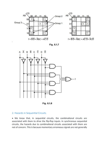
- 77. 2. Hazards in Sequential Circuits • We know that, in sequential circuits, the combinational circuits are associated with them to drive the flip-flop inputs. In synchronous sequential circuits, the hazards due to combinational circuits associated with them are not of concern. This is because momentary erromeous signals are not generally
- 78. troublesome in synchronous circuits. However, if a momentary incorrect signal is fed back in an asynchronous sequential circuit, it may cause the circuit to go to the wrong stable state. • Let us consider the logic diagram and its transition table as shown in Fig. 8.1.9. For the circuit shown in Fig. 8.1.9, if the circuit is in total stable state YX1X2 = 111 and input X2 changes from 1 to 0, the next total stable state should be YX1X2 = 110. However, because of hazard, the output Y may go to 0 momentarily. If this false signal feeds back into AND2 before the output of the inverter goes to 1, the output of AND2 will remain at 0 and the circuit will switch to the incorrect total stable state 010. • Such a hazard can be eliminated by enclosing two minterms by another minterm as shown in the Fig. 8.1.10.
- 79. • Therefore, the hazard free asynchronous sequential circuit will be as shown in Fig. 8.1.11. 3. Essential Hazards • In the previous section we have seen static and dynamic hazards and remedies to remove it. There is another type of hazard that may occur in asynchronous sequential circuits, called essential hazards. An essential hazard is caused by unequal delays along two or more paths that originate from the
- 80. same input. Such hazards can be eliminated by adjusting the amount of delays in the affected path. Two Marks Questions with Answers Q.1 What are hazards ? Ans. : The unwanted switching transients (glitches) that may appear at the output of a circuit are called Hazards. Q.2 What are the two types of hazards ? Ans. : The two types of hazards are : 1. Static hazard 2. Dynamic hazard. Q.3 What is static hazard ? Ans. : A static hazard exists if a signal is supposed to remain at particular logic value when an input variable changes its value, but instead the signal undergoes a momentary change in its required value. Q.4 What are static-0 and static-1 hazards ? AU : May-13, 15 Ans. : In a combinational circuit, if output goes momentarily 0 when it should remain a 1, the hazard is known as static-1 hazard. On the other hand, if output goes momentarily 1 when it should remain a 0, the hazard is known as static-0 hazard. Q.5 Explain dynamic hazard.
- 81. Ans. : The hazard in which output changes three or more times when it should change from 1 to 0 or from 0 to 1 is called dynamic hazard. Q.6 What is the cause of essential hazard ? AU : May-03, 12, Dec.-04 Ans. : An essential hazard is caused by unequal delays along two or more paths that originate from the same input. Such hazards can be eliminated by adjusting the amount of delays in the affected path. University Questions with Answers (Long Answered Questions) (Regulation 2008) Dec.-12 Q.1 Wliaf are hazards in sequential circuits ? How can they he eliminated ? [Section 8.1] [6] (Regulation 2013) Dec.-14 Q.2 Explain the various types of hazards in sequential circuit design and the methods to eliminate them. Give suitable examples. [Section 8.1] [16] May-16 Q.3 What are static - 0 and static - 1 hazards ? Explain the removal of hazards using hazard covers in K-map. [Section 8.1] [8] May-17 Q.4 Implement the following logic and analyse for the pressure of any hazard If hazard is present briefly explain the type of hazard and design a hazard - free circuit. (Refer section 8.1.1) [7] Dec.-17
- 82. Q.5 What is hazards ? Explain hazards in digital circuits. (Refer section 8.1) [6] Dec.-18 Q.6 Illustrate about hazards in sequential circuits and the steps to avoid hazards in it. (Refer section 8.1.2) [13]