SlideShare a Scribd company logo
Dr.B.Vidhya
Assistant Professor, CT
Sri Ramakrishna College of Arts & Science
UNIT- I
Introduction to Codes
IntroductiontotheCodes
The first successful system of electrical communication was the
telegraph, which was invented by Samuel F.B. Morse in the year 1832.
The telegraph operators used a code of clicks to send the messages.
If the key pressed for a short time it is the Morse code called ‘dot’ and
if the key pressed for a long-time it is ‘Dash’.
A sample Morse code is shown in next slide
IntroductiontotheCodes
If it is observed logically, various innumerable combinations of dots and dashes of any kind
of words (even sentences) can be written utilizing the above code.
IntroductiontotheCodes
In the same way, binary digits also be utilized to make such various innumerable
combinations. These may be considered as Binary Codes.
Other than the commonly used 8421 code or BCD code, other Binary Codes like
2421 code, 5211 code, reflective code, sequential code, non-weighted code,
excess-3 code and Gray code are also popular.
Digital Fundamental - Binary Codes-Logic Gates
WeightedCodes
Weighted binary codes are those binary codes which obey the positional
weight principle.
Each position of the number represents a specific weight. Several systems of
the codes are used to express the decimal digits 0 through 9. In these codes
each decimal digit is represented by a group of four bits.
Non-WeightedCodes
Some of the codes will not follow the weights of the sequence binary numbers
these are called as non-weighted codes.
ASCII code and Grey code are some of the examples where they are coded for
some special purpose applications and they do not follow the weighted binary
number calculations.
Binary Code
Binary code, code used in digital computers, based on a binary number system
in which there are only two possible states, off and on, usually symbolized by 0 and
1.
Whereas in a decimal system, which employs 10 digits, each digit position
represents a power of 10 (100, 1,000, etc.), in a binary system each digit position
represents a power of 2 (4, 8, 16, etc.).
A binary code signal is a series of electrical pulses that represent numbers,
characters, and operations to be performed.
Binary Code
In binary code, each decimal number (0–9) is represented by a set of four binary
digits, or bits.
The four fundamental arithmetic operations (addition, subtraction, multiplication,
and division) can all be reduced to combinations of fundamental Boolean algebraic
operations on binary numbers.
See the table below for how the decimal
numbers from 0 to 10 are represented
in binary.)
Binary Weights
Whenever any binary number appears, its decimal equivalent can be found
easily as follows.
● When there is 1 in a digit position, weight of that position should be added.
● When there is 0 in a digit position, weight of that position should be
disregarded.
For example binary number 1100 has a decimal equivalent of 8 + 4 + 0 + 0 = 12.
Binary CodeDecimal
The BCD8421 code is so called because
each of the four bits is given a ‘weighting’
according to its column value in the
binary system.
The least significant bit (lsb) has the
weight or value 1, the next bit, going left,
the value 2.
The next bit has the value 4, and the
most significant bit (msb) the value 8, as
shown in Table 1.6.1.
Binary CodeDecimal
So the 8421BCD code for the decimal number 610 is 01108421.
For numbers greater than 9 the system is extended by using a second block of 4
bits to represent tens and a third block to represent hundreds etc.
2410 in 8 bit binary would be 00011000 but in BCD8421 is 0010 0100.
99210 in 16 bit binary would be 00000011111000002 but in BCD8421 is 1001 1001
0010.
ExcessCode-3
As mentioned above, some of the codes will
not follow the binary weights, Excess-3 code is
an example of it and it is an important 4 bit
code. The excess – 3 code of a decimal
number is achieved by adding the number 3 to
the 8421 code.
For example to convert 15 to an excess-3
code, first 3 to be added to each digit as shown
below.
Excess-3Codeexamples
Find the excess-3 code of (237.75)10
The excess-3 code for (237)10 is obtained by adding 3 to all the digits individually, that is 2, 3
and 7 will become 5, 6 and 10 respectively. These 5, 6 and 10 decimals have to be
converted into binary form and the result is 010101101010.
The excess-3 code for (.75)10 is obtained by replacing 7 and 5 with 10 and 8 respectively by
adding 3 to each digit. That is, the excess-3 code for (.75)10 is .10101000.
Combining the results of the integral and fractional parts, the excess-3 code for (237.75)10 is
010101101010.10101000.
Excess-3Codeexamples
Find the decimal number of excess-3 number 110010100011.01110101.
The excess-3 code is 110010100011.01110101
By separating 4 bits as group the equivalent excess-3 code is given as 1100 1010
0011.0111 0101.
Subtracting 0011 from each four-bit group, we obtain the new number as: 1001
0111 0000.0100 0010.
Therefore, the decimal equivalent is (970.42)10.
GrayCode
Definition: Gray Code is the minimum-change code category of coding in which,
the two consecutive values changes by only a single bit. More specifically we can
say,
it is a binary number system where while moving from one step to the next, only a
single bit shows variation.
It is also termed as reflected binary code or cyclic code. It is an unweighted
code, as here like other number systems, no particular weight is provided to
various bit positions.
GrayCode
Basically, binary code is changed to gray
equivalent in order to lessen the switching
operations.As only a single bit is changed at a
particular time duration this leads to a
reduction in switching from one bit to another.
Let us have a look at the tabular
representation, showing gray value for
different binary values:
Decimal
Value
Binary Code
Gray
Code
0 0000 0000
1 0001 0001
2 0010 0011
3 0011 0010
4 0100 0110
5 0101 0111
6 0110 0101
7 0111 0100
GrayCode
8 1000 1100
9 1001 1101
A 1010 1111
B 1011 1110
C 1100 1010
D 1101 1011
E 1110 1001
F 1111 1000
GrayCode
Consider decimal value 7 and 8, to understand the switching of bits.
We know in binary, 7 is written as 0111 while 8 is written as 1000.
Thus we can conclude that in a binary system, all 4 bits are getting changed
simultaneously. Hence we can say multiple bits are changing at the same time.
In gray code, 7 is written as 0100, as against 8 is written as 1100.
IntroductiontoParity Code
In digital electronics system or digital communication system, the information is
transmitted from one system to another system or from one circuit to another in a binary
form.
While transmitting the information, an error may occur due to the presence of noise. An
error is said to occur, if a signal corresponding to 0 may change to 1 or vice versa.
It is not always possible to avoid those errors, but it is possible to detect and correct the
error. First, it is important to detect an error. It is done by adding an extra bit to the
transmitted data.
There are different codes like parity code, block parity, hamming code, etc to detect and
correct the errors. In this section, you will learn in detail about the parity code.
Parity Codes
The parity code is used for the purpose of detecting errors during the transmission
of binary information. The parity code is a bit that is included with the binary data
to be transmitted.
The inclusion of a parity bit will make the number of 1’s either odd or even. Based
on the number of 1’s in the transmitted data, the parity code is of two types.
● Even parity code
● Odd parity code
Parity Codes
In even parity, the added parity bit will make the total number of 1’s an even
number. If the added parity bit make the total number of 1’s as odd number, such
parity code is said to be odd parity code.
Let us consider the 4-bit message(1011) to be transmitted. Adding 1 to the message
will make the total number of 1’s in the message to be an even number. Hence it is
called as even parity.
Parity Codes
For the same message, adding 0 with the transmitted message will make the total
number of 1’s to be an odd number. Hence it is called as odd parity. It is shown in
the example below.
Parity Codes
The following table shows the some of the 4-bit messages to be transmitted along
with the parity bits.
The bits in red color are the parity bits.
4-bit message Message with
Odd parity
Message with
Even Parity
0000 00001 00000
0001 00010 00011
0010 00100 00101
0011 00111 00110
0100 01000 01001
0101 01011 01010
0110 01101 01100
0111 01110 01111
Parity Codes
On the receiver side, if the received data is other than the sent data, then it is an error. If the
sent date is even parity code and the received data is odd parity, then there is an error.
So, both even and odd parity codes are used only for the detection of error and not for the
correction in the transmitted data. Even parity is commonly used and it has almost become a
convention.
ASCII Codes
ASCII, abbreviation of American Standard Code For Information
Interchange.
A standard data-transmission code that is used by smaller and less-powerful
computers to represent both textual data (letters, numbers, and punctuation
marks) and noninput-device commands (control characters).
Like other coding systems, it converts information into standardized digital
formats that allow computers to communicate with each other and to efficiently
process and store data.
ASCII Codes
The standard ASCII code uses seven-digit
consisting of various sequences of 0’s and 1’s.
binary numbers; i.e., numbers
The code can represent 128 different characters, since there are 128 different
possible combinations of seven 0’s and 1’s.
The binary sequence 1010000, for example, represents an uppercase “P,” while the
sequence 1110000 represents a lowercase “p.”
ASCII Codes
Digital computers use a binary code that is arranged in groups of eight rather than
of seven digits, or bits. Each such eight-digit group is called a byte.
Because digital computers use eight-bit bytes, the ASCII code is commonly
embedded in an eight-bit field consisting of the seven information bits and a parity
bit that is used for error-checking purposes or to represent special symbols.
The use of an eight-bit system increased the number of characters the code could
represent to 256.
The eight-bit system, which is known as the extended ASCII code, was introduced
in 1981 by the International Business Machines Corporation (IBM) for use with its
first model of personal computer. This extended ASCII code soon became the
industry-wide standard for personal computers.
IntroductiontoLogicGates
A logic gate is an idealized model of computation or physical electronic device
implementing a Boolean function, a logical operation performed on one or more
binary inputs that produces a single binary output.
Logic gates are the basic building blocks of any digital system. It is an electronic
circuit having one or more than one input and only one output.
The relationship between the input and the output is based on a certain logic.
Based on this, logic gates are named as AND gate, OR gate, NOT gate etc.
ClassificationofLogicgates
ANDGATE
An AND gate is a logic gate having two or more inputs and a single output. An
AND gate operates on logical multiplication rules.
In this gate, if either of the inputs is low (0), then the output is also low. If all of the
inputs are high (1), then the output will also be high.
An AND gate can have any number of inputs, although 2 input and 3 input AND
gates are the most common.
ANDGATE- Symbol&TimeTable
A circuit which performs an AND operation is shown in figure. It has n input (n >=
2) and one output.
ORGATE
An OR gate is a digital logic gate with two or more inputs and one output that
performs logical disjunction.
The output of an OR gate is true when one or more of its inputs are true. If all of
an OR gate's inputs are false, then the output of the OR gate is false.
A circuit which performs an OR operation is shown in figure. It has n input (n >= 2)
and one output.
ORGATE- Symbol&TruthTable
NOTGate
A logical inverter, sometimes called a NOT gate to differentiate it from other types
of electronic inverter devices, has only one input. It reverses the logic state. If the
input is 1, then the output is 0. If the input is 0, then the output is 1.
NOT gate is also known as Inverter. It has one input A and one output Y.
NOTGate-Truthtable&Symbol
NANDGate
The NAND gate operates as an AND gate followed by a NOT gate. It acts in the
manner of the logical operation "and" followed by negation. The output is "false" if
both inputs are "true." Otherwise, the output is "true."
A NOT-AND operation is known as NAND operation. It has n input (n >= 2) and
one output.
NANDGATE-TruthTable&Symbols
NORGate
The NOR gate is a combination OR gate followed by an inverter. Its output is
"true" if both inputs are "false." Otherwise, the output is "false."
A NOT-OR operation is known as NOR operation. It has n input (n >= 2) and one
output.
NORGate-Symbols&truthtable
EX-ORGATE
The Exclusive-OR gate or XOR gate is achieved by combining standard logic gates
together.
XOR gate is used extensively in error detection circuits, computational logic
comparators and arithmetic logic circuits.
The Exclusive OR gate gives an output only if its two inputs are dissimilar, namely
if one of them is high (one) and the other is low (zero).
EX-ORGate-Symbols&truthtable
EX-NORGate-Symbols&truthtable
Exclusive-NOR gate is formed by combining the Exclusive-OR gate (XOR gate) and
the NOT gate.
On analysing the truth table of Exclusive-NOR gate, we understand that the output
is similar to the standard NOR gate except that the output of the Ex-NOR gate is
high when both inputs are high.
The output of EX-NOR gate is 1 when both the inputs are 1 (high) and if both the
inputs are 0 (low).
If either one of the input is 1 (high) the output will be 0 (low). In other words, both
the inputs should be in the same logic level for the output to be 1.
EX-NORGate-Symbols&truthtable

More Related Content

Similar to Digital Fundamental - Binary Codes-Logic Gates (20)

PPTX
Code Converters & Parity Checker
.AIR UNIVERSITY ISLAMABAD
 
PPTX
3.codes( binary code ,excess 3, gray code )
MdFazleRabbi18
 
PPT
Error detection and correction codes
GargiKhanna1
 
PPTX
Coding Schemes related dld lecture it is dld
shayan03239
 
PPT
Fundamentals of Electrical and electronic engineering Binary code,grey code,o...
njr200505
 
PPTX
Binary and EC codes
Mahesh Singh Madai
 
PDF
Codes: Binary Codes Weighted codes Binary Coded Decimal (BCD) Non-weighted ...
Bharati Ingale
 
PDF
Lecture5 Chapter1- Binary Codes.pdf
UmerKhan147799
 
PDF
W3 Chapter 2B Notes CCB1223 Digital Logic.pdf
MOHDZAMRIBINIBRAHIM1
 
PDF
Binary codes
GargiKhanna1
 
PDF
Unit 1 Class Notes Printed digital Electronics.pdf
drdeepakgupta1307
 
PPTX
Codes r005
arunachalamr16
 
PDF
Digital logic degin, Number system
Ashish Kumar Thakur
 
PPTX
Chapter 1: Binary System
Er. Nawaraj Bhandari
 
PPTX
Introduction to Computer Logical Organization
BINJAD1
 
PPTX
DLD-W3-L1.pptx
aneesurrehman54
 
PPTX
Introduction to number system
AswiniT3
 
PPT
digital___electronics___EXPLAINATION.ppt
Harshal Vaidya
 
PDF
Information Science in Action Week 3 Codes
ValentinusRobyHanant
 
Code Converters & Parity Checker
.AIR UNIVERSITY ISLAMABAD
 
3.codes( binary code ,excess 3, gray code )
MdFazleRabbi18
 
Error detection and correction codes
GargiKhanna1
 
Coding Schemes related dld lecture it is dld
shayan03239
 
Fundamentals of Electrical and electronic engineering Binary code,grey code,o...
njr200505
 
Binary and EC codes
Mahesh Singh Madai
 
Codes: Binary Codes Weighted codes Binary Coded Decimal (BCD) Non-weighted ...
Bharati Ingale
 
Lecture5 Chapter1- Binary Codes.pdf
UmerKhan147799
 
W3 Chapter 2B Notes CCB1223 Digital Logic.pdf
MOHDZAMRIBINIBRAHIM1
 
Binary codes
GargiKhanna1
 
Unit 1 Class Notes Printed digital Electronics.pdf
drdeepakgupta1307
 
Codes r005
arunachalamr16
 
Digital logic degin, Number system
Ashish Kumar Thakur
 
Chapter 1: Binary System
Er. Nawaraj Bhandari
 
Introduction to Computer Logical Organization
BINJAD1
 
DLD-W3-L1.pptx
aneesurrehman54
 
Introduction to number system
AswiniT3
 
digital___electronics___EXPLAINATION.ppt
Harshal Vaidya
 
Information Science in Action Week 3 Codes
ValentinusRobyHanant
 

More from VidhyaB10 (12)

PPT
Preprocessing - Data Integration Tuple Duplication
VidhyaB10
 
PPT
Major Tasks in Data Preprocessing - Data cleaning
VidhyaB10
 
PPT
Applications ,Issues & Technology in Data mining -
VidhyaB10
 
PPTX
Python Visualization API Primersubplots
VidhyaB10
 
PPTX
Python _dataStructures_ List, Tuples, its functions
VidhyaB10
 
PPTX
Python_Functions_Modules_ User define Functions-
VidhyaB10
 
PPT
Datamining - Introduction - Knowledge Discovery in Databases
VidhyaB10
 
PPTX
INSTRUCTION PROCESSOR DESIGN Computer system architecture
VidhyaB10
 
PPTX
Disk Scheduling in OS computer deals with multiple processes over a period of...
VidhyaB10
 
PPTX
Unit 2 digital fundamentals boolean func.pptx
VidhyaB10
 
PPTX
unit 5-files.pptx
VidhyaB10
 
PPTX
Python_Unit1_Introduction.pptx
VidhyaB10
 
Preprocessing - Data Integration Tuple Duplication
VidhyaB10
 
Major Tasks in Data Preprocessing - Data cleaning
VidhyaB10
 
Applications ,Issues & Technology in Data mining -
VidhyaB10
 
Python Visualization API Primersubplots
VidhyaB10
 
Python _dataStructures_ List, Tuples, its functions
VidhyaB10
 
Python_Functions_Modules_ User define Functions-
VidhyaB10
 
Datamining - Introduction - Knowledge Discovery in Databases
VidhyaB10
 
INSTRUCTION PROCESSOR DESIGN Computer system architecture
VidhyaB10
 
Disk Scheduling in OS computer deals with multiple processes over a period of...
VidhyaB10
 
Unit 2 digital fundamentals boolean func.pptx
VidhyaB10
 
unit 5-files.pptx
VidhyaB10
 
Python_Unit1_Introduction.pptx
VidhyaB10
 
Ad

Recently uploaded (20)

PPTX
Neurodivergent Friendly Schools - Slides from training session
Pooky Knightsmith
 
PPTX
QUARTER 1 WEEK 2 PLOT, POV AND CONFLICTS
KynaParas
 
PDF
ARAL-Orientation_Morning-Session_Day-11.pdf
JoelVilloso1
 
PDF
The Different Types of Non-Experimental Research
Thelma Villaflores
 
PDF
The History of Phone Numbers in Stoke Newington by Billy Thomas
History of Stoke Newington
 
PPT
Talk on Critical Theory, Part II, Philosophy of Social Sciences
Soraj Hongladarom
 
PPTX
How to Handle Salesperson Commision in Odoo 18 Sales
Celine George
 
PDF
CONCURSO DE POESIA “POETUFAS – PASSOS SUAVES PELO VERSO.pdf
Colégio Santa Teresinha
 
PPTX
CATEGORIES OF NURSING PERSONNEL: HOSPITAL & COLLEGE
PRADEEP ABOTHU
 
PDF
Stokey: A Jewish Village by Rachel Kolsky
History of Stoke Newington
 
PPTX
Growth and development and milestones, factors
BHUVANESHWARI BADIGER
 
PPT
Talk on Critical Theory, Part One, Philosophy of Social Sciences
Soraj Hongladarom
 
PDF
QNL June Edition hosted by Pragya the official Quiz Club of the University of...
Pragya - UEM Kolkata Quiz Club
 
PPTX
ASRB NET 2023 PREVIOUS YEAR QUESTION PAPER GENETICS AND PLANT BREEDING BY SAT...
Krashi Coaching
 
PPTX
PPT-Q1-WEEK-3-SCIENCE-ERevised Matatag Grade 3.pptx
reijhongidayawan02
 
PPTX
GRADE-3-PPT-EVE-2025-ENG-Q1-LESSON-1.pptx
EveOdrapngimapNarido
 
PPTX
Stereochemistry-Optical Isomerism in organic compoundsptx
Tarannum Nadaf-Mansuri
 
PPTX
grade 5 lesson matatag ENGLISH 5_Q1_PPT_WEEK4.pptx
SireQuinn
 
PDF
Generative AI: it's STILL not a robot (CIJ Summer 2025)
Paul Bradshaw
 
PDF
Reconstruct, Restore, Reimagine: New Perspectives on Stoke Newington’s Histor...
History of Stoke Newington
 
Neurodivergent Friendly Schools - Slides from training session
Pooky Knightsmith
 
QUARTER 1 WEEK 2 PLOT, POV AND CONFLICTS
KynaParas
 
ARAL-Orientation_Morning-Session_Day-11.pdf
JoelVilloso1
 
The Different Types of Non-Experimental Research
Thelma Villaflores
 
The History of Phone Numbers in Stoke Newington by Billy Thomas
History of Stoke Newington
 
Talk on Critical Theory, Part II, Philosophy of Social Sciences
Soraj Hongladarom
 
How to Handle Salesperson Commision in Odoo 18 Sales
Celine George
 
CONCURSO DE POESIA “POETUFAS – PASSOS SUAVES PELO VERSO.pdf
Colégio Santa Teresinha
 
CATEGORIES OF NURSING PERSONNEL: HOSPITAL & COLLEGE
PRADEEP ABOTHU
 
Stokey: A Jewish Village by Rachel Kolsky
History of Stoke Newington
 
Growth and development and milestones, factors
BHUVANESHWARI BADIGER
 
Talk on Critical Theory, Part One, Philosophy of Social Sciences
Soraj Hongladarom
 
QNL June Edition hosted by Pragya the official Quiz Club of the University of...
Pragya - UEM Kolkata Quiz Club
 
ASRB NET 2023 PREVIOUS YEAR QUESTION PAPER GENETICS AND PLANT BREEDING BY SAT...
Krashi Coaching
 
PPT-Q1-WEEK-3-SCIENCE-ERevised Matatag Grade 3.pptx
reijhongidayawan02
 
GRADE-3-PPT-EVE-2025-ENG-Q1-LESSON-1.pptx
EveOdrapngimapNarido
 
Stereochemistry-Optical Isomerism in organic compoundsptx
Tarannum Nadaf-Mansuri
 
grade 5 lesson matatag ENGLISH 5_Q1_PPT_WEEK4.pptx
SireQuinn
 
Generative AI: it's STILL not a robot (CIJ Summer 2025)
Paul Bradshaw
 
Reconstruct, Restore, Reimagine: New Perspectives on Stoke Newington’s Histor...
History of Stoke Newington
 
Ad

Digital Fundamental - Binary Codes-Logic Gates

  • 1. Dr.B.Vidhya Assistant Professor, CT Sri Ramakrishna College of Arts & Science UNIT- I Introduction to Codes
  • 2. IntroductiontotheCodes The first successful system of electrical communication was the telegraph, which was invented by Samuel F.B. Morse in the year 1832. The telegraph operators used a code of clicks to send the messages. If the key pressed for a short time it is the Morse code called ‘dot’ and if the key pressed for a long-time it is ‘Dash’. A sample Morse code is shown in next slide
  • 3. IntroductiontotheCodes If it is observed logically, various innumerable combinations of dots and dashes of any kind of words (even sentences) can be written utilizing the above code.
  • 4. IntroductiontotheCodes In the same way, binary digits also be utilized to make such various innumerable combinations. These may be considered as Binary Codes. Other than the commonly used 8421 code or BCD code, other Binary Codes like 2421 code, 5211 code, reflective code, sequential code, non-weighted code, excess-3 code and Gray code are also popular.
  • 6. WeightedCodes Weighted binary codes are those binary codes which obey the positional weight principle. Each position of the number represents a specific weight. Several systems of the codes are used to express the decimal digits 0 through 9. In these codes each decimal digit is represented by a group of four bits.
  • 7. Non-WeightedCodes Some of the codes will not follow the weights of the sequence binary numbers these are called as non-weighted codes. ASCII code and Grey code are some of the examples where they are coded for some special purpose applications and they do not follow the weighted binary number calculations.
  • 8. Binary Code Binary code, code used in digital computers, based on a binary number system in which there are only two possible states, off and on, usually symbolized by 0 and 1. Whereas in a decimal system, which employs 10 digits, each digit position represents a power of 10 (100, 1,000, etc.), in a binary system each digit position represents a power of 2 (4, 8, 16, etc.). A binary code signal is a series of electrical pulses that represent numbers, characters, and operations to be performed.
  • 9. Binary Code In binary code, each decimal number (0–9) is represented by a set of four binary digits, or bits. The four fundamental arithmetic operations (addition, subtraction, multiplication, and division) can all be reduced to combinations of fundamental Boolean algebraic operations on binary numbers. See the table below for how the decimal numbers from 0 to 10 are represented in binary.)
  • 10. Binary Weights Whenever any binary number appears, its decimal equivalent can be found easily as follows. ● When there is 1 in a digit position, weight of that position should be added. ● When there is 0 in a digit position, weight of that position should be disregarded. For example binary number 1100 has a decimal equivalent of 8 + 4 + 0 + 0 = 12.
  • 11. Binary CodeDecimal The BCD8421 code is so called because each of the four bits is given a ‘weighting’ according to its column value in the binary system. The least significant bit (lsb) has the weight or value 1, the next bit, going left, the value 2. The next bit has the value 4, and the most significant bit (msb) the value 8, as shown in Table 1.6.1.
  • 12. Binary CodeDecimal So the 8421BCD code for the decimal number 610 is 01108421. For numbers greater than 9 the system is extended by using a second block of 4 bits to represent tens and a third block to represent hundreds etc. 2410 in 8 bit binary would be 00011000 but in BCD8421 is 0010 0100. 99210 in 16 bit binary would be 00000011111000002 but in BCD8421 is 1001 1001 0010.
  • 13. ExcessCode-3 As mentioned above, some of the codes will not follow the binary weights, Excess-3 code is an example of it and it is an important 4 bit code. The excess – 3 code of a decimal number is achieved by adding the number 3 to the 8421 code. For example to convert 15 to an excess-3 code, first 3 to be added to each digit as shown below.
  • 14. Excess-3Codeexamples Find the excess-3 code of (237.75)10 The excess-3 code for (237)10 is obtained by adding 3 to all the digits individually, that is 2, 3 and 7 will become 5, 6 and 10 respectively. These 5, 6 and 10 decimals have to be converted into binary form and the result is 010101101010. The excess-3 code for (.75)10 is obtained by replacing 7 and 5 with 10 and 8 respectively by adding 3 to each digit. That is, the excess-3 code for (.75)10 is .10101000. Combining the results of the integral and fractional parts, the excess-3 code for (237.75)10 is 010101101010.10101000.
  • 15. Excess-3Codeexamples Find the decimal number of excess-3 number 110010100011.01110101. The excess-3 code is 110010100011.01110101 By separating 4 bits as group the equivalent excess-3 code is given as 1100 1010 0011.0111 0101. Subtracting 0011 from each four-bit group, we obtain the new number as: 1001 0111 0000.0100 0010. Therefore, the decimal equivalent is (970.42)10.
  • 16. GrayCode Definition: Gray Code is the minimum-change code category of coding in which, the two consecutive values changes by only a single bit. More specifically we can say, it is a binary number system where while moving from one step to the next, only a single bit shows variation. It is also termed as reflected binary code or cyclic code. It is an unweighted code, as here like other number systems, no particular weight is provided to various bit positions.
  • 17. GrayCode Basically, binary code is changed to gray equivalent in order to lessen the switching operations.As only a single bit is changed at a particular time duration this leads to a reduction in switching from one bit to another. Let us have a look at the tabular representation, showing gray value for different binary values: Decimal Value Binary Code Gray Code 0 0000 0000 1 0001 0001 2 0010 0011 3 0011 0010 4 0100 0110 5 0101 0111 6 0110 0101 7 0111 0100
  • 18. GrayCode 8 1000 1100 9 1001 1101 A 1010 1111 B 1011 1110 C 1100 1010 D 1101 1011 E 1110 1001 F 1111 1000
  • 19. GrayCode Consider decimal value 7 and 8, to understand the switching of bits. We know in binary, 7 is written as 0111 while 8 is written as 1000. Thus we can conclude that in a binary system, all 4 bits are getting changed simultaneously. Hence we can say multiple bits are changing at the same time. In gray code, 7 is written as 0100, as against 8 is written as 1100.
  • 20. IntroductiontoParity Code In digital electronics system or digital communication system, the information is transmitted from one system to another system or from one circuit to another in a binary form. While transmitting the information, an error may occur due to the presence of noise. An error is said to occur, if a signal corresponding to 0 may change to 1 or vice versa. It is not always possible to avoid those errors, but it is possible to detect and correct the error. First, it is important to detect an error. It is done by adding an extra bit to the transmitted data. There are different codes like parity code, block parity, hamming code, etc to detect and correct the errors. In this section, you will learn in detail about the parity code.
  • 21. Parity Codes The parity code is used for the purpose of detecting errors during the transmission of binary information. The parity code is a bit that is included with the binary data to be transmitted. The inclusion of a parity bit will make the number of 1’s either odd or even. Based on the number of 1’s in the transmitted data, the parity code is of two types. ● Even parity code ● Odd parity code
  • 22. Parity Codes In even parity, the added parity bit will make the total number of 1’s an even number. If the added parity bit make the total number of 1’s as odd number, such parity code is said to be odd parity code. Let us consider the 4-bit message(1011) to be transmitted. Adding 1 to the message will make the total number of 1’s in the message to be an even number. Hence it is called as even parity.
  • 23. Parity Codes For the same message, adding 0 with the transmitted message will make the total number of 1’s to be an odd number. Hence it is called as odd parity. It is shown in the example below.
  • 24. Parity Codes The following table shows the some of the 4-bit messages to be transmitted along with the parity bits. The bits in red color are the parity bits. 4-bit message Message with Odd parity Message with Even Parity 0000 00001 00000 0001 00010 00011 0010 00100 00101 0011 00111 00110 0100 01000 01001 0101 01011 01010 0110 01101 01100 0111 01110 01111
  • 25. Parity Codes On the receiver side, if the received data is other than the sent data, then it is an error. If the sent date is even parity code and the received data is odd parity, then there is an error. So, both even and odd parity codes are used only for the detection of error and not for the correction in the transmitted data. Even parity is commonly used and it has almost become a convention.
  • 26. ASCII Codes ASCII, abbreviation of American Standard Code For Information Interchange. A standard data-transmission code that is used by smaller and less-powerful computers to represent both textual data (letters, numbers, and punctuation marks) and noninput-device commands (control characters). Like other coding systems, it converts information into standardized digital formats that allow computers to communicate with each other and to efficiently process and store data.
  • 27. ASCII Codes The standard ASCII code uses seven-digit consisting of various sequences of 0’s and 1’s. binary numbers; i.e., numbers The code can represent 128 different characters, since there are 128 different possible combinations of seven 0’s and 1’s. The binary sequence 1010000, for example, represents an uppercase “P,” while the sequence 1110000 represents a lowercase “p.”
  • 28. ASCII Codes Digital computers use a binary code that is arranged in groups of eight rather than of seven digits, or bits. Each such eight-digit group is called a byte. Because digital computers use eight-bit bytes, the ASCII code is commonly embedded in an eight-bit field consisting of the seven information bits and a parity bit that is used for error-checking purposes or to represent special symbols. The use of an eight-bit system increased the number of characters the code could represent to 256. The eight-bit system, which is known as the extended ASCII code, was introduced in 1981 by the International Business Machines Corporation (IBM) for use with its first model of personal computer. This extended ASCII code soon became the industry-wide standard for personal computers.
  • 29. IntroductiontoLogicGates A logic gate is an idealized model of computation or physical electronic device implementing a Boolean function, a logical operation performed on one or more binary inputs that produces a single binary output. Logic gates are the basic building blocks of any digital system. It is an electronic circuit having one or more than one input and only one output. The relationship between the input and the output is based on a certain logic. Based on this, logic gates are named as AND gate, OR gate, NOT gate etc.
  • 31. ANDGATE An AND gate is a logic gate having two or more inputs and a single output. An AND gate operates on logical multiplication rules. In this gate, if either of the inputs is low (0), then the output is also low. If all of the inputs are high (1), then the output will also be high. An AND gate can have any number of inputs, although 2 input and 3 input AND gates are the most common.
  • 32. ANDGATE- Symbol&TimeTable A circuit which performs an AND operation is shown in figure. It has n input (n >= 2) and one output.
  • 33. ORGATE An OR gate is a digital logic gate with two or more inputs and one output that performs logical disjunction. The output of an OR gate is true when one or more of its inputs are true. If all of an OR gate's inputs are false, then the output of the OR gate is false. A circuit which performs an OR operation is shown in figure. It has n input (n >= 2) and one output.
  • 35. NOTGate A logical inverter, sometimes called a NOT gate to differentiate it from other types of electronic inverter devices, has only one input. It reverses the logic state. If the input is 1, then the output is 0. If the input is 0, then the output is 1. NOT gate is also known as Inverter. It has one input A and one output Y.
  • 37. NANDGate The NAND gate operates as an AND gate followed by a NOT gate. It acts in the manner of the logical operation "and" followed by negation. The output is "false" if both inputs are "true." Otherwise, the output is "true." A NOT-AND operation is known as NAND operation. It has n input (n >= 2) and one output.
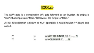
  • 39. NORGate The NOR gate is a combination OR gate followed by an inverter. Its output is "true" if both inputs are "false." Otherwise, the output is "false." A NOT-OR operation is known as NOR operation. It has n input (n >= 2) and one output.
  • 41. EX-ORGATE The Exclusive-OR gate or XOR gate is achieved by combining standard logic gates together. XOR gate is used extensively in error detection circuits, computational logic comparators and arithmetic logic circuits. The Exclusive OR gate gives an output only if its two inputs are dissimilar, namely if one of them is high (one) and the other is low (zero).
  • 43. EX-NORGate-Symbols&truthtable Exclusive-NOR gate is formed by combining the Exclusive-OR gate (XOR gate) and the NOT gate. On analysing the truth table of Exclusive-NOR gate, we understand that the output is similar to the standard NOR gate except that the output of the Ex-NOR gate is high when both inputs are high. The output of EX-NOR gate is 1 when both the inputs are 1 (high) and if both the inputs are 0 (low). If either one of the input is 1 (high) the output will be 0 (low). In other words, both the inputs should be in the same logic level for the output to be 1.