2. E-R Model
Definition -
•The entity-relationship model (or ER model)
is a way of graphically representing the
logical relationships of entities (or objects) in
order to create a database. The ER model
was first proposed by Peter Pin-Shan Chen
of Massachusetts Institute of Technology
(MIT) in the 1970s
6. Features
• It has high degree of data independence
• The ER model is a top-down approach in
system design.
• It can be used as a basis for unification
views of data such as network, relational
modeling.
• It was developed after the relational
database when the industry shifted attention
to transaction processing.
7. Entity
• An entity is an object that exists and is
distinguishable from other objects.
• Might be Object with physical existence
like Lect, student, car.
• Object with conceptual or logical existence
like course, job, postion.
8. – An ENTITY SET is the collection of all entities of a
particular entity type in the database at any point of time.
– Example:, companies, trees, Employee etc
REPRESENT IN
E-R DIAGRAM
Rectangles represent entity type
Entity Type:- a collection of similar entities
E1.
E2
E3
E4
EMPLOYEE
9. • A set of entities that have
the same attributes is
called an entity type.
Each entity type in the
database is described by
a name and a list of
attributes.
• For example an entity
EMPLOYEE is an entity
type that has Name, Age
and Salary attributes.
• The individual entities of
a particular entity type are
grouped into a collection
or entity set, which is
also called the extension
of the entity type.
An entity is a thing in the
real world. It may be an
object with a physical
existence or an object
with a conceptual
existence.
10. ENTITY SET corresponding to the
ENTITY TYPE CAR
car1
((ABC 123, TEXAS), TK629, Ford Mustang, convertible, 1999, (red, black))
car2
((ABC 123, NEW YORK), WP9872, Nissan 300ZX, 2-door, 2002, (blue))
car3
((VSY 720, TEXAS), TD729, Buick LeSabre, 4-door, 2003, (white, blue))
.
.
.
CAR
Registration(RegistrationNumber, State), VehicleID, Make, Model, Year, (Color)
11. we can also understand this by an anology .
entity type is like fruit which is a class .we havn't seen any
"fruit"yet though we have seen instance of fruit like
"apple ,banana,mango etc.hence..
fruit=entity type=EMPLOYEE
apple=entity=e1 or e2 or e3
enity set= bucket of apple,banana ,mango etc={e1,e2......}
12. Attributes
• Attributes are properties used to describe an
entity. For example an EMPLOYEE entity may
have a Name, SSN, Address, Sex, BirthDate.
• Attribute Domain: The set of allowable values
for one or more attributes.
• Attributes can be classified as being: simple or
composite; single-valued or multi-valued; or
derived.
13. Types of Attributes (1)
• Simple
– Each entity has a single atomic value for the attribute. For
example, SSN or Sex.
• Composite
– The attribute may be composed of several components. For
example, Address (Apt#, House#, Street, City, State,
ZipCode, Country) or Name (FirstName, MiddleName,
LastName). Composition may form a hierarchy where some
components are themselves composite.
• Multi-valued
– An entity may have multiple values for that attribute. For
example, Color of a CAR or mobile number.
14. Types of Attributes (2)
• Single values:- attribute that have only one value for
each entity e.g. name,age for employee.
• Derived:-attribute contain values that are derived from
other attributes e.g. age can be derived from DOB &
current date
• Null Value :- unknown value e.g. PF no. of employee
STORED ATTRIBUTE:-Attributes that are directly
stored in the database and can not derived from other
one are called stored attributes .
For example, Birth Date attribute of a STUDENT entity
15. • STRONG ENTITY SETS
An entity set containing a key attribute are called strong
entity types or regular entity types.
For example, The STUDENT entity has a key attribute
Roll No which uniquely identifies it, hence is a strong
entity set.
• WEAK ENTITY SETS
An entity set may not have sufficient attribute to form a
primary key. Entity types that do not contain any key
attributes, and hence can not be identified independently
are called weak entity sets.
• A weak entity can be identified uniquely only by
considering some of its attributes in conjunction with the
primary key attribute of another entity, which is called the
identifying owner entity
16. NOTATION FOR
ER SCHEMAS
ENTITY TYPE
WEAK ENTITY TYPE
RELATIONSHIP TYPE
IDENTIFYING RELATIONSHIP TYPE
ATTRIBUTE
KEY ATTRIBUTE
MULTIVALUED ATTRIBUTE
COMPOSITE ATTRIBUTE
DERIVED ATTRIBUTE
TOTAL PARTICIPATION OF E2 IN R
CARDINALITY RATIO 1:N FOR E1:E2
IN R
STRUCTURAL CONSTRAINT (min,
max) ON PARTICIPATION OF E IN R
E1 E2
E1 E2
R
(min,max)
E
R
R
N
17. Relationships and Relationship
Types (1)
• A relationship relates two or more distinct entities with a
specific meaning. For example, EMPLOYEE John
Smith works on the ProductX PROJECT or EMPLOYEE
Franklin Wong manages the Research DEPARTMENT.
18. Example relationship instances of the WORKS_FOR
relationship between EMPLOYEE and DEPARTMENT
e1
e2
e3
e4
e5
e6
e7
EMPLOYEE
r1
r2
r3
r4
r5
r6
r7
WORKS_FOR
d1
d2
d3
DEPARTMENT
19. Degree of a Relationship Type
• The degree of a relationship type is the number
of participating entity types.
• unary(recursive) relationship type :- that
involves only one entity.
• Binary relationship type :-has 2 entity type link
together.
• Ternary:- if there are 3 entity type link toghter.
20. Mapping Cardinalities
• Express the number of entities to which another
entity can be associated via a relationship set.
• Most useful in describing binary relationship sets.
• For a binary relationship set the mapping cardinality
must be one of the following types:
– One to one
– One to many
– Many to one
– Many to many
21. • A one to one relationship -For example, There is
only one manager that manages one department, so
it is a one to one (1:1) relationship
• A one to many relationship - one manager
manages many employees, but each employee only
has one manager, so it is a one to many (1:n)
relationship
• A many to one relationship - many students study
one course. They do not study more than one course,
so it is a many to one (m:1) relationship
• A many to many relationship - One lecturer
teaches many students and a student is taught by
many lecturers, so it is a many to many (m:n)
relationship
23. Slide 3- 24
Constraints on Relationships
• Constraints on Relationship Types
(Also known as ratio constraints)
–Cardinality Ratio (specifies maximum participation)
• One-to-one (1:1)
• One-to-many (1:N) or Many-to-one (N:1)
• Many-to-many (M:N)
–Existence Dependency Constraint (specifies minimum
participation) (also called participation constraint)
• zero (optional participation, not existence-dependent)
• one or more (mandatory participation, existence-
dependent)
25. Example of 1:1 Relationship (with one Partial and one total Partition)
This is represented as:
Cardinality: 1 1
Participation: 0 1
Employee Department
Manages
1 1
26. Example of 1:1 Relationship with (Min, Max) Representation
This is represented as:
Cardinality: 1 1
Participation: 0 1
Employee Department
Manages
(0,1) (1,1)
27. Many to 1 Relationship (N:1) or 1 to Many Relationship (1:N)
This is represented as:
Cardinality: 1 N
Participation: 1 1
Employee Department
Works
For
N 1
28. Many to 1 Relationship (N:1) or 1 to Many Relationship (1:N)
This is represented as:
Cardinality: 1 N
Participation: 1 1
Employee Department
Works
For
(1,1) (1,N)
with (Min, Max)
Representation
29. Many to Many Relationship (M:N)
This is represented as:
Cardinality: M N
Participation: 1 1
Employee Project
Works
On
N M
30. Many to Many Relationship (M:N) with (Min, Max) Representation
This is represented as:
Cardinality: M N
Participation: 1 1
Employee Project
Works
On
(1,M) (1,N)
31. Slide 3- 32
Displaying a recursive relationship
• In a recursive relationship type.
– Both participations are same entity type in
different roles.
– For example, SUPERVISION relationships
between EMPLOYEE (in role of supervisor or
boss) and (another) EMPLOYEE (in role of
subordinate or worker).
• In following figure, first role participation
labeled with 1 and second role participation
labeled with 2.
• In ER diagram, need to display role names to
distinguish participations.
32. Example relationship instances of the WORKS_FOR
relationship between EMPLOYEE and DEPARTMENT
This is represented as:
Cardinality: N 1
Participation: 0 0
Employee Employee
Super
vises
1 N
Supervisor Supervisee
Employee
Super
vises
Supervisor Supervisee
1 N
33. Example relationship instances of the WORKS_FOR
relationship between EMPLOYEE and DEPARTMENT
This is represented as:
Cardinality: N 1
Participation: 0 0
Employee Employee
Super
vises
(0,N) (0,1)
Supervisor Supervisee
Employee
Super
vises
Supervisor Supervisee
(0,N) (0,1)
with (Min, Max) Representation
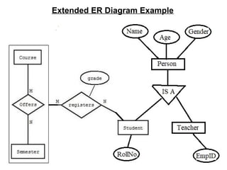
39. Extended(Enhanced ) ER Model:
• The ER modeling concepts are sufficient for representing
traditional database application. For more complex
database application such as telecommunications,
CAD/CAM, GIS etc, we need more complex
requirements than traditional applications.
• In late 1970’s database designers have tried to
design more accurate ER model, which reflects the
data properties and constraints more accurately. So
extended (Enhanced) ER model have some enhanced
features than normal ER model. It uses the concepts of
Specialization, Generalization and Aggregation.
40. Specialization:
• Specialization is the process through which we
can relate one entity to more than one entity. In
other words specialization is the process to
defining a set of subclasses of an entity type.
• This entity is called superclass. For ex. An
entity “employee” has the sub entity, ‘faculty’,
‘Staff’. So employee has the relation with both
the sub entity. This relation name is “IS A”. as
shown in fig. So Specialization follow the
process of one to many relationship.
42. Generalization:
• Generalization is just reverse of Specialization.
Generalization is the process to define a generalized entity
type from the given entity type.
• For ex. Consider the two entity CAR and TRUCK. Because
both have some common attributes, they can be combined
to make a super entity called VEHICLE.
• So it is the process to identify the common features
(attributes) from two or more entities and generalized them
into a super entity.
• Several classes with common features are generalized into
a superclass and original classes become its subclasses
46. Aggregation:
• Aggregation is a process when relation between two
entity is treated as a single entity. Here the relation
between Center and Course, is acting as an Entity in
relation with Visitor.
48. ER Model to Relational Model – Conversion
To convert the ER model to relational model there are
7 Steps to be followed, which are:
1. Conversion of Strong Entities
2. Conversion of Weak Entities
3. Conversion of one to one Relationships
4. Conversion of One to Many Relationships
5. Conversion of Many to Many Relationships
6. Conversion of n-ary Relationships
7. Conversion of Multivalued Attribute
49. 1. Conversion of Strong Entities –
•For each strong entity in ERD, create a separate table with the
same name.
•Create all simple Attributes
•Break the Composite attributes into simple attributes & create
them.
•Choose a Primary Key for the table.
50. 2. Conversion of Weak Entities
•For each weak entity, create a separate table with the same name.
•Include Primary Key of the strong entity as a foreign key in the
table.
•Select the Primary Key attributes of strong entity and the partial
Key attribute of the weak entity, and declare them as primary key.
51. 3. Conversion of One to One Relationships
There are two possible approaches on the basis of Participation
Constraints –
1. Partial Participation on Both Sides –
•For each One to One Cardinality between E1 and E2 with
partial participation on both sides, modify either E1 or E2 to
include the primary key of other table as a foreign key. So, 1:1
cardinality with partial participation on both sides can be
minimized into two relations only.
•If we try to minimize the above ERD in a single table, i.e.
E1RE2, then it contains too many NULL values, and therefore,
we are not be able to select a primary key.
53. 2. Cardinality with atleast one Total Participation – For each One to
One Cardinality between E1 and E2 with atleast one total participation,
modification is done only on total participation side.
So, One to One Cardinality with atleast one Total Participation can be
minimized into a single relation.
54. 4. Conversion of One to Many or Many to One Relationship –
For each one to many relationship between E1 and E2, modify
many side relation to include from one side as a Foreign Key.
55. 5. Conversion of Many to Many Relationship –
For each one to many relationship between E1 and E2, create a separate
table and include primary key of both the tables as a Foreign Key.
If relationship is having one or more attributes, then these must also be
included in the table.
M N
56. 6. Conversion of n-ary Relationship –
For each n-ary relationship, Create a separate table and include primary keys of
all other entities as a foreign key.
If the relationships has some attributes, then these must also be included in the
table.
57. 7. Conversion of multivalued Attributes –
For each multivalued attributes, create a separate table, then include all
of its simple attributes.
Include the primary key of the original table as a foreign key.