SlideShare a Scribd company logo
2
Most read
e-PG Pathshala
Subject : Computer Science
Paper: Embedded System
Module: Embedded Software Development Tools
Module No: CS/ES/36
Quadrant 1 – e-text
In this module, we will discuss about the host and target machine, Embedded Software
development process and Embedded tools.
1.1 Purpose of Embedded System
An embedded system is a special-purpose system in which the computer is completely
encapsulated by the device it controls. Each embedded system has unique characteristics.
The components and functions of hardware and software can be different for each system.
Nowadays, embedded software is used in all the electronic devices such as watches,
cellular phones etc. This embedded software is similar to general programming. But the
embedded hardware is unique. The method of communication between interfaces can
vary from processor to processor. It leads to more complexity of software. Engineers need
to be aware of the software developing process and tools. There are a lot of things that
software development tools can do automatically when the target platform is well defined.
This automation is possible because the tools can exploit features of the hardware and
operating system on which your program will execute. Embedded software development
tools can rarely make assumptions about the target platform. Hence the user has to provide
some explicit instructions of the system to the tools. Figure 1.1 shows how an embedded
system is developed using a host and a target machine.
1.2 Host and Target machine
Figure 1.1 Embedded system using host and target machine
1.2.1 Performance of Host machine
The application program developed runs on the host computer. The host computer is also
called as Development Platform. It is a general purpose computer. It has a higher capability
processor and more memory. It has different input and output devices. The compiler,
assembler, linker, and locator run on a host computer rather than on the embedded system
itself. These tools are extremely popular with embedded software developers because they
are freely available (even the source code is free) and support many of the most popular
embedded processors. It contains many development tools to create the output binary
image. Once a program has been written, compiled, assembled and linked, it is moved to
the target platform.
1.2.2 Performance of Target machine
The output binary image is executed on the target hardware platform. It consists of two
entities - the target hardware (processor) and runtime environment (OS). It is needed only
for final output. It is different from the development platform and it does not contain any
development tools.
1.3 Embedded Software Development process
Figure 1.2 Embedded Software Development process
The embedded software development process just described is illustrated in Figure 1.2. In
this figure, the three steps are shown from top to bottom, with the tools that perform the
steps shown in boxes which are having rounded corners. Each tool can take one or more
files as input and produces a single output file. This transformation process is performed by
the software running on a general-purpose computer. The compiler, assembler, linker, and
locator run on a host computer. These tools are combined to produce an executable binary
image. This output binary image runs on a target embedded system.
1.3.1 Software development process
In a general purpose computer, the following are the steps to develop a software.
Step 1 : Create a source file.
Step 2 : Type the high level (say C) code depending on the application.
Step 3 : Build a project file, compile the code and link to other libraries and object file etc.
Step 4 : Execute the code and run the program.
In Embedded system it is a different procedure. Following are steps to develop embedded
system software.
Step 1 : Create a source file.
Step 2 : Type the high-level (predominantly) C code depending on the application.
Step 3 : Compile the code using a compiler and translate into machine code on host
Step 4 : Linker combines all the object files and libraries to resolve all symbols
Step 5 : Locater assigns the memory addresses to code and data
Step 6 : The executable image is copied into the target processor and reset to
initiate/refresh for new run.
1.4 Types of Embedded tools
Development of embedded software requires many tools. They are Editor, Assembler,
Compiler, Linker, Simulator, Profiler. Embedded Hardware tools that are used to develop
the hardware include In-Circuit-Emulator, Debugger, Starter Kit.
Figure 1.3 Flow of embedded system.
The flow of an embedded system development is shown in figure 1.3. The written source
code is sent to preprocessor. It is then processed by the compiler, assembler and linker to
make an executable code. It is embedded in the hardware to make the embedded system.
Let us discuss the software tools in detail.
1.4.1 Compiler
Compiler is a software program that converts a source code from high level language into
low level language. In other words compiler translates programs written in human-readable
language into machine language.
Source Code --> Object file
This object file is a binary file that contains a set of machine-language instructions
(opcodes) and data resulting from language translation process. Machine-language
instructions are specific to a particular processor. The compiler that runs on a computer
platform and produces code for that same computer platform is called as native compiler.
A Compiler that runs on one computer platform and produces code for another computer
platform is called as cross compiler. Each processor has its own unique machine language.
Compilers can support standard object file formats such as COFF (Common Object File
Format) , ELF(Executable and linkable Format) etc.
1.4.2 Assembler/Interpreters
In some cases, compilers do not have support to convert into assembly code. Then that
program will move to an assembler. An assembler is a software program that converts the
source code of assembly language into machine language. It performs one-to-one
translation from human-readable assembly language (Mnemonics) to equivalent machine-
language (opcodes). The input of the assembler must be assembly language. An
assembler that runs on host but produces binary instruction appropriate for some other
target is called cross-assembler.
An interpreter constantly runs and interprets source code as a set of directives. As the
program is typed, the assembler performs syntax checking. The performance is very poor,
as it can be 1000x slower than an equivalent compiled language. However, the interactive
capability provides more feedback. It is easier to learn.
1.4.3 Linking
A linker or link editor is a program that takes one or more objects generated by compilers
and assembles them into a single executable program. The linker combines the object files
from compiler and resolves variable and function references. Source code may be
contained in more than one file. Hence, it must be combined.
It resolves the variables which may be referenced in one file and defined in another file. It
also resolves calls to library functions, like sqrt. It may include the operating system . The
output of the linker is a new object file that contains all the codes and data from the input
object files. If the same symbol is declared in more than one object file, the linker is unable
to proceed.
The linker creates a relocatable version of the program. The entire embedded application
including the operating system is statically linked together and executed as a single binary
image.
Startup code
Startup code is a small block of assembly language code that prepares the way for the
execution of software written in a high-level language. Each high-level language has its
own set of expectations about the runtime environment. Usually, the startup code is not
inserted automatically, the programmer assembles it and includes the resulting object file
among the list of input files to the linker. Most cross-compilers for embedded systems
include an assembly language file called startup.asm, crt0.s or something similar. The
location and contents of this file are usually described in the documentation supplied with
the compiler.
This Startup code for C programs usually consists of the following series of actions:
1. Disable all interrupts.
2. Copy any initialized data from ROM to RAM.
3. Zero the uninitialized data area.
4. Allocate space for and initialize the stack.
5. Initialize the processor's stack pointer.
6. Call main.
It includes a few instructions after the call to main. These instructions will be executed only in
the event that the high-level language program executes.
1.4.4 Locator
A Locator is a tool that performs the conversion from relocatable program to executable
binary image. The locator assigns physical memory addresses to code and data sections
within the relocatable program. The locator produces a binary memory image that can be
loaded into the target ROM. In contrast, on general purpose computers, the operating
system assigns the addresses at load time. The memory information required by the GNU
linker can be passed to it in the form of a linker script. These scripts are used to control the
exact order of the code and data sections within the relocatable program. A sample script is
shown below.
Linker script file
ENTRY (main)
MEMORY
{
ram : ORIGIN = 0x00400000, LENGTH = 64M
rom : ORIGIN = 0x60000000, LENGTH = 16M
}
SECTIONS
{
data : /* Initialized data. */
{
_DataStart = . ;
*(.data)
_DataEnd = . ;
} >ram
bss : /* Uninitialized data. */
{
_BssStart = . ;
*(.bss)
_BssEnd = . ;
} >ram
text : /* The actual instructions. */
{
*(.text)
} >ram
}
This script informs the built-in locator about the memory on the target board, which contains
64 MB of RAM and 16 MB of flash ROM. A linker script can use various commands to direct
the linker to perform other operations. The output of this final step of process is a binary
image containing physical addresses for the specific embedded system. This executable
binary image can be downloaded to the embedded system or programmed into a memory
chip. Embedded system software is burned into hardware with this procedure.
2. Summary
In this module, we discussed about the Host and Target machines. The development of
embedded software process was also explained. We then discussed the embedded
software tools. .
3. References
1. Michael Barr, Ambony massa, ”Programming Embedded Systems, Second Edition
with C and GNU Development Tools”, Second edition, O’REILLY publications, 2006.
2. Wayne Wolf, “Computers as components: Principles of embedded computing
systems design”; Second edition, published by Morgan Kaufmann series(2008).

More Related Content

Similar to Embedded systems designUNIT 4 PART 2.pdf (20)

PDF
report
Diptika Shukla
 
DOCX
PPS UNIT 1- R18.docx
Uzma1102
 
PPTX
Introduction.pptx
SUDHAKAR S
 
PDF
Module4.pdf ,...................................
chetanreddy2212
 
PPT
Introduction to compiler design and phases of compiler
Ranjeet Reddy
 
PPTX
Ch 1.pptx
woldu2
 
PPTX
Chapter 2 Program language translation.pptx
dawod yimer
 
PPTX
Es tools ppt
Halai Hansika
 
PPTX
Embedded System Tools ppt
Halai Hansika
 
PPTX
System software module 1 presentation file
jithujithin657
 
PPTX
system software and application software, compiler, interpreter & assembler
chetan birla
 
PPT
Embedded systems
PROVAB TECHNOSOFT PVT. LTD.
 
PPTX
Chapter 1.pptx compiler design lecture note
adugnanegero
 
PDF
System programming note
SANTOSH RATH
 
PDF
System Programming VV Notes.pdf
bharathreddy223930
 
PDF
Chapter1pdf__2021_11_23_10_53_20.pdf
DrIsikoIsaac
 
PDF
SPCC:System programming and compiler construction
mohdumaira1
 
PDF
Namdeo Kapale Sanjivani College of Engineering KopaCFP_UNIT1_24-25.pdf
NAMDEO5
 
PDF
Linker and Loader Explained
Adarsh Kr Sinha
 
PPTX
ESSENTIAL COMPONENTS OF COMPUTERS(UNIT 2)
Dr. SURBHI SAROHA
 
PPS UNIT 1- R18.docx
Uzma1102
 
Introduction.pptx
SUDHAKAR S
 
Module4.pdf ,...................................
chetanreddy2212
 
Introduction to compiler design and phases of compiler
Ranjeet Reddy
 
Ch 1.pptx
woldu2
 
Chapter 2 Program language translation.pptx
dawod yimer
 
Es tools ppt
Halai Hansika
 
Embedded System Tools ppt
Halai Hansika
 
System software module 1 presentation file
jithujithin657
 
system software and application software, compiler, interpreter & assembler
chetan birla
 
Embedded systems
PROVAB TECHNOSOFT PVT. LTD.
 
Chapter 1.pptx compiler design lecture note
adugnanegero
 
System programming note
SANTOSH RATH
 
System Programming VV Notes.pdf
bharathreddy223930
 
Chapter1pdf__2021_11_23_10_53_20.pdf
DrIsikoIsaac
 
SPCC:System programming and compiler construction
mohdumaira1
 
Namdeo Kapale Sanjivani College of Engineering KopaCFP_UNIT1_24-25.pdf
NAMDEO5
 
Linker and Loader Explained
Adarsh Kr Sinha
 
ESSENTIAL COMPONENTS OF COMPUTERS(UNIT 2)
Dr. SURBHI SAROHA
 

More from vmspraneeth (16)

PPT
VLSI fabrication -Twin Tub Processes.ppt
vmspraneeth
 
PPT
VLSI bi cmos technology processes ppt.ppt
vmspraneeth
 
PPTX
U III embedded system MOTION CONTROL QEI.pptx
vmspraneeth
 
PPTX
U III ES Digital to Analog Converter PART.pptx
vmspraneeth
 
PPTX
UNIT III Embedded Systems architecture.pptx
vmspraneeth
 
PDF
embedded system components and applications notes1.pdf
vmspraneeth
 
PPTX
UNIT 4 LINEAR INTEGRATED CIRCUITS-DIGITAL ICS
vmspraneeth
 
PPTX
UNIT-III- DATA CONVERTERS ANALOG TO DIGITAL CONVERTER
vmspraneeth
 
PPTX
LINEAR INTEGRATED CIRCUITS UNIT 2 FILTERS AND DESIGN
vmspraneeth
 
PPTX
LINEAR INTEGRATED CIRCUITS UNIT 1 LINEAR AND DIGITAL IC
vmspraneeth
 
PPT
Noise infotheory1
vmspraneeth
 
PDF
Action verbsforobjectives
vmspraneeth
 
PPTX
U 4 automation_in_digital
vmspraneeth
 
PPTX
U 4 ramp digital voltmeter
vmspraneeth
 
PDF
3 ec2352 – computer networks
vmspraneeth
 
PPT
registers_&_counters
vmspraneeth
 
VLSI fabrication -Twin Tub Processes.ppt
vmspraneeth
 
VLSI bi cmos technology processes ppt.ppt
vmspraneeth
 
U III embedded system MOTION CONTROL QEI.pptx
vmspraneeth
 
U III ES Digital to Analog Converter PART.pptx
vmspraneeth
 
UNIT III Embedded Systems architecture.pptx
vmspraneeth
 
embedded system components and applications notes1.pdf
vmspraneeth
 
UNIT 4 LINEAR INTEGRATED CIRCUITS-DIGITAL ICS
vmspraneeth
 
UNIT-III- DATA CONVERTERS ANALOG TO DIGITAL CONVERTER
vmspraneeth
 
LINEAR INTEGRATED CIRCUITS UNIT 2 FILTERS AND DESIGN
vmspraneeth
 
LINEAR INTEGRATED CIRCUITS UNIT 1 LINEAR AND DIGITAL IC
vmspraneeth
 
Noise infotheory1
vmspraneeth
 
Action verbsforobjectives
vmspraneeth
 
U 4 automation_in_digital
vmspraneeth
 
U 4 ramp digital voltmeter
vmspraneeth
 
3 ec2352 – computer networks
vmspraneeth
 
registers_&_counters
vmspraneeth
 
Ad

Recently uploaded (20)

PDF
Zero Carbon Building Performance standard
BassemOsman1
 
PDF
Air -Powered Car PPT by ER. SHRESTH SUDHIR KOKNE.pdf
SHRESTHKOKNE
 
PDF
2025 Laurence Sigler - Advancing Decision Support. Content Management Ecommer...
Francisco Javier Mora Serrano
 
PDF
STUDY OF NOVEL CHANNEL MATERIALS USING III-V COMPOUNDS WITH VARIOUS GATE DIEL...
ijoejnl
 
DOCX
SAR - EEEfdfdsdasdsdasdasdasdasdasdasdasda.docx
Kanimozhi676285
 
PPTX
sunil mishra pptmmmmmmmmmmmmmmmmmmmmmmmmm
singhamit111
 
PPTX
MULTI LEVEL DATA TRACKING USING COOJA.pptx
dollysharma12ab
 
PPTX
ENSA_Module_7.pptx_wide_area_network_concepts
RanaMukherjee24
 
PPTX
Precedence and Associativity in C prog. language
Mahendra Dheer
 
PDF
2010_Book_EnvironmentalBioengineering (1).pdf
EmilianoRodriguezTll
 
PDF
Biodegradable Plastics: Innovations and Market Potential (www.kiu.ac.ug)
publication11
 
PPTX
Introduction to Fluid and Thermal Engineering
Avesahemad Husainy
 
PPTX
Ground improvement techniques-DEWATERING
DivakarSai4
 
PDF
Construction of a Thermal Vacuum Chamber for Environment Test of Triple CubeS...
2208441
 
PDF
All chapters of Strength of materials.ppt
girmabiniyam1234
 
PPTX
IoT_Smart_Agriculture_Presentations.pptx
poojakumari696707
 
PPTX
filteration _ pre.pptx 11111110001.pptx
awasthivaibhav825
 
PDF
Packaging Tips for Stainless Steel Tubes and Pipes
heavymetalsandtubes
 
PPTX
Module2 Data Base Design- ER and NF.pptx
gomathisankariv2
 
PPTX
MT Chapter 1.pptx- Magnetic particle testing
ABCAnyBodyCanRelax
 
Zero Carbon Building Performance standard
BassemOsman1
 
Air -Powered Car PPT by ER. SHRESTH SUDHIR KOKNE.pdf
SHRESTHKOKNE
 
2025 Laurence Sigler - Advancing Decision Support. Content Management Ecommer...
Francisco Javier Mora Serrano
 
STUDY OF NOVEL CHANNEL MATERIALS USING III-V COMPOUNDS WITH VARIOUS GATE DIEL...
ijoejnl
 
SAR - EEEfdfdsdasdsdasdasdasdasdasdasdasda.docx
Kanimozhi676285
 
sunil mishra pptmmmmmmmmmmmmmmmmmmmmmmmmm
singhamit111
 
MULTI LEVEL DATA TRACKING USING COOJA.pptx
dollysharma12ab
 
ENSA_Module_7.pptx_wide_area_network_concepts
RanaMukherjee24
 
Precedence and Associativity in C prog. language
Mahendra Dheer
 
2010_Book_EnvironmentalBioengineering (1).pdf
EmilianoRodriguezTll
 
Biodegradable Plastics: Innovations and Market Potential (www.kiu.ac.ug)
publication11
 
Introduction to Fluid and Thermal Engineering
Avesahemad Husainy
 
Ground improvement techniques-DEWATERING
DivakarSai4
 
Construction of a Thermal Vacuum Chamber for Environment Test of Triple CubeS...
2208441
 
All chapters of Strength of materials.ppt
girmabiniyam1234
 
IoT_Smart_Agriculture_Presentations.pptx
poojakumari696707
 
filteration _ pre.pptx 11111110001.pptx
awasthivaibhav825
 
Packaging Tips for Stainless Steel Tubes and Pipes
heavymetalsandtubes
 
Module2 Data Base Design- ER and NF.pptx
gomathisankariv2
 
MT Chapter 1.pptx- Magnetic particle testing
ABCAnyBodyCanRelax
 
Ad

Embedded systems designUNIT 4 PART 2.pdf

  • 1. e-PG Pathshala Subject : Computer Science Paper: Embedded System Module: Embedded Software Development Tools Module No: CS/ES/36 Quadrant 1 – e-text In this module, we will discuss about the host and target machine, Embedded Software development process and Embedded tools. 1.1 Purpose of Embedded System An embedded system is a special-purpose system in which the computer is completely encapsulated by the device it controls. Each embedded system has unique characteristics. The components and functions of hardware and software can be different for each system. Nowadays, embedded software is used in all the electronic devices such as watches, cellular phones etc. This embedded software is similar to general programming. But the embedded hardware is unique. The method of communication between interfaces can vary from processor to processor. It leads to more complexity of software. Engineers need to be aware of the software developing process and tools. There are a lot of things that software development tools can do automatically when the target platform is well defined. This automation is possible because the tools can exploit features of the hardware and operating system on which your program will execute. Embedded software development tools can rarely make assumptions about the target platform. Hence the user has to provide some explicit instructions of the system to the tools. Figure 1.1 shows how an embedded system is developed using a host and a target machine. 1.2 Host and Target machine Figure 1.1 Embedded system using host and target machine 1.2.1 Performance of Host machine
  • 2. The application program developed runs on the host computer. The host computer is also called as Development Platform. It is a general purpose computer. It has a higher capability processor and more memory. It has different input and output devices. The compiler, assembler, linker, and locator run on a host computer rather than on the embedded system itself. These tools are extremely popular with embedded software developers because they are freely available (even the source code is free) and support many of the most popular embedded processors. It contains many development tools to create the output binary image. Once a program has been written, compiled, assembled and linked, it is moved to the target platform. 1.2.2 Performance of Target machine The output binary image is executed on the target hardware platform. It consists of two entities - the target hardware (processor) and runtime environment (OS). It is needed only for final output. It is different from the development platform and it does not contain any development tools. 1.3 Embedded Software Development process Figure 1.2 Embedded Software Development process The embedded software development process just described is illustrated in Figure 1.2. In this figure, the three steps are shown from top to bottom, with the tools that perform the steps shown in boxes which are having rounded corners. Each tool can take one or more files as input and produces a single output file. This transformation process is performed by the software running on a general-purpose computer. The compiler, assembler, linker, and locator run on a host computer. These tools are combined to produce an executable binary image. This output binary image runs on a target embedded system. 1.3.1 Software development process In a general purpose computer, the following are the steps to develop a software.
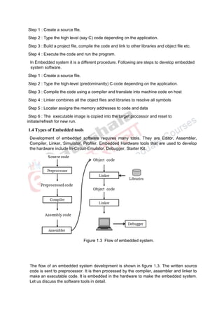
  • 3. Step 1 : Create a source file. Step 2 : Type the high level (say C) code depending on the application. Step 3 : Build a project file, compile the code and link to other libraries and object file etc. Step 4 : Execute the code and run the program. In Embedded system it is a different procedure. Following are steps to develop embedded system software. Step 1 : Create a source file. Step 2 : Type the high-level (predominantly) C code depending on the application. Step 3 : Compile the code using a compiler and translate into machine code on host Step 4 : Linker combines all the object files and libraries to resolve all symbols Step 5 : Locater assigns the memory addresses to code and data Step 6 : The executable image is copied into the target processor and reset to initiate/refresh for new run. 1.4 Types of Embedded tools Development of embedded software requires many tools. They are Editor, Assembler, Compiler, Linker, Simulator, Profiler. Embedded Hardware tools that are used to develop the hardware include In-Circuit-Emulator, Debugger, Starter Kit. Figure 1.3 Flow of embedded system. The flow of an embedded system development is shown in figure 1.3. The written source code is sent to preprocessor. It is then processed by the compiler, assembler and linker to make an executable code. It is embedded in the hardware to make the embedded system. Let us discuss the software tools in detail.
  • 4. 1.4.1 Compiler Compiler is a software program that converts a source code from high level language into low level language. In other words compiler translates programs written in human-readable language into machine language. Source Code --> Object file This object file is a binary file that contains a set of machine-language instructions (opcodes) and data resulting from language translation process. Machine-language instructions are specific to a particular processor. The compiler that runs on a computer platform and produces code for that same computer platform is called as native compiler. A Compiler that runs on one computer platform and produces code for another computer platform is called as cross compiler. Each processor has its own unique machine language. Compilers can support standard object file formats such as COFF (Common Object File Format) , ELF(Executable and linkable Format) etc. 1.4.2 Assembler/Interpreters In some cases, compilers do not have support to convert into assembly code. Then that program will move to an assembler. An assembler is a software program that converts the source code of assembly language into machine language. It performs one-to-one translation from human-readable assembly language (Mnemonics) to equivalent machine- language (opcodes). The input of the assembler must be assembly language. An assembler that runs on host but produces binary instruction appropriate for some other target is called cross-assembler. An interpreter constantly runs and interprets source code as a set of directives. As the program is typed, the assembler performs syntax checking. The performance is very poor, as it can be 1000x slower than an equivalent compiled language. However, the interactive capability provides more feedback. It is easier to learn. 1.4.3 Linking A linker or link editor is a program that takes one or more objects generated by compilers and assembles them into a single executable program. The linker combines the object files from compiler and resolves variable and function references. Source code may be contained in more than one file. Hence, it must be combined. It resolves the variables which may be referenced in one file and defined in another file. It also resolves calls to library functions, like sqrt. It may include the operating system . The output of the linker is a new object file that contains all the codes and data from the input object files. If the same symbol is declared in more than one object file, the linker is unable to proceed. The linker creates a relocatable version of the program. The entire embedded application including the operating system is statically linked together and executed as a single binary image. Startup code Startup code is a small block of assembly language code that prepares the way for the execution of software written in a high-level language. Each high-level language has its own set of expectations about the runtime environment. Usually, the startup code is not
  • 5. inserted automatically, the programmer assembles it and includes the resulting object file among the list of input files to the linker. Most cross-compilers for embedded systems include an assembly language file called startup.asm, crt0.s or something similar. The location and contents of this file are usually described in the documentation supplied with the compiler. This Startup code for C programs usually consists of the following series of actions: 1. Disable all interrupts. 2. Copy any initialized data from ROM to RAM. 3. Zero the uninitialized data area. 4. Allocate space for and initialize the stack. 5. Initialize the processor's stack pointer. 6. Call main. It includes a few instructions after the call to main. These instructions will be executed only in the event that the high-level language program executes. 1.4.4 Locator A Locator is a tool that performs the conversion from relocatable program to executable binary image. The locator assigns physical memory addresses to code and data sections within the relocatable program. The locator produces a binary memory image that can be loaded into the target ROM. In contrast, on general purpose computers, the operating system assigns the addresses at load time. The memory information required by the GNU linker can be passed to it in the form of a linker script. These scripts are used to control the exact order of the code and data sections within the relocatable program. A sample script is shown below. Linker script file ENTRY (main) MEMORY { ram : ORIGIN = 0x00400000, LENGTH = 64M rom : ORIGIN = 0x60000000, LENGTH = 16M } SECTIONS { data : /* Initialized data. */ { _DataStart = . ; *(.data)
  • 6. _DataEnd = . ; } >ram bss : /* Uninitialized data. */ { _BssStart = . ; *(.bss) _BssEnd = . ; } >ram text : /* The actual instructions. */ { *(.text) } >ram } This script informs the built-in locator about the memory on the target board, which contains 64 MB of RAM and 16 MB of flash ROM. A linker script can use various commands to direct the linker to perform other operations. The output of this final step of process is a binary image containing physical addresses for the specific embedded system. This executable binary image can be downloaded to the embedded system or programmed into a memory chip. Embedded system software is burned into hardware with this procedure. 2. Summary In this module, we discussed about the Host and Target machines. The development of embedded software process was also explained. We then discussed the embedded software tools. . 3. References 1. Michael Barr, Ambony massa, ”Programming Embedded Systems, Second Edition with C and GNU Development Tools”, Second edition, O’REILLY publications, 2006. 2. Wayne Wolf, “Computers as components: Principles of embedded computing systems design”; Second edition, published by Morgan Kaufmann series(2008).