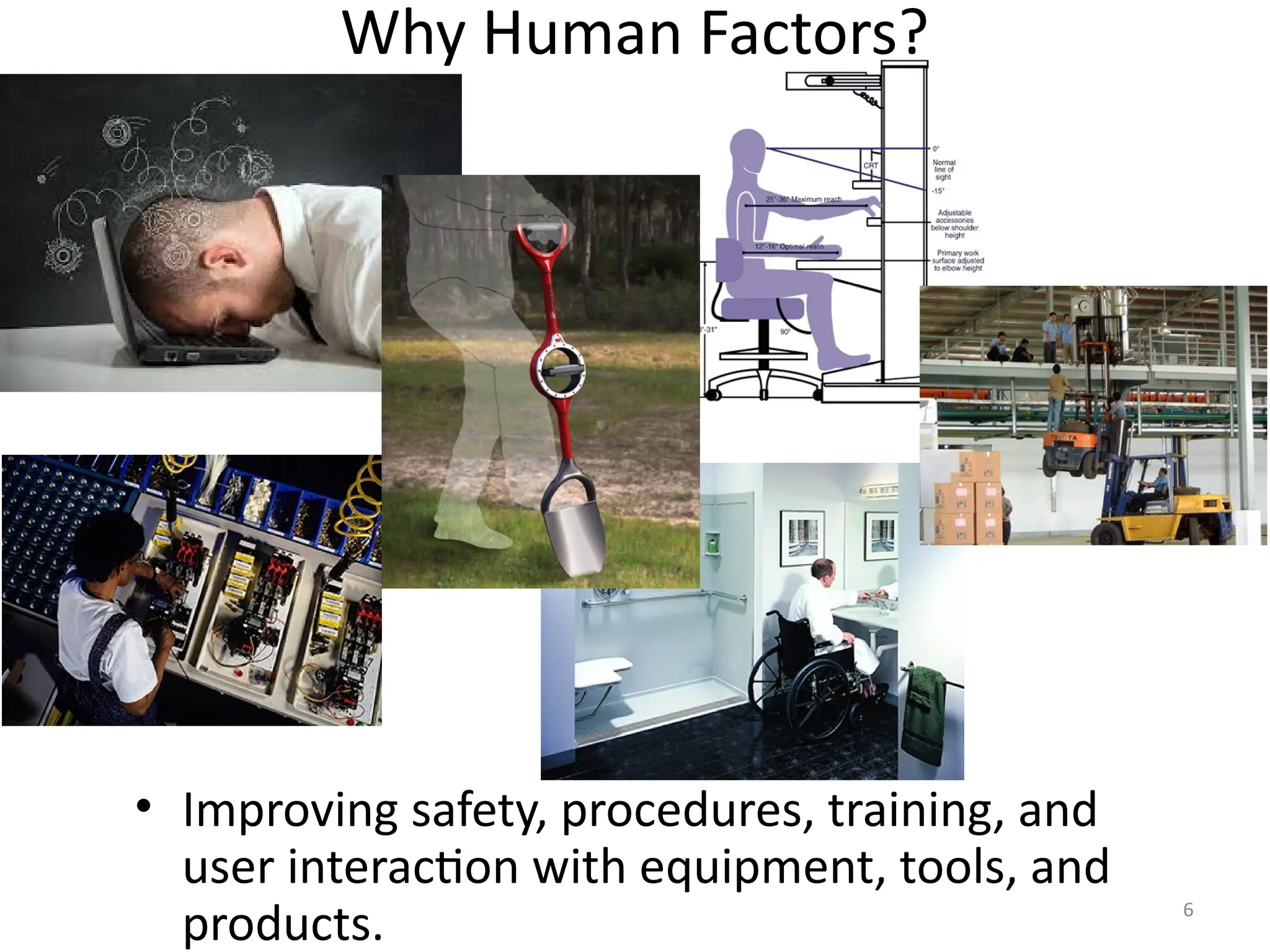
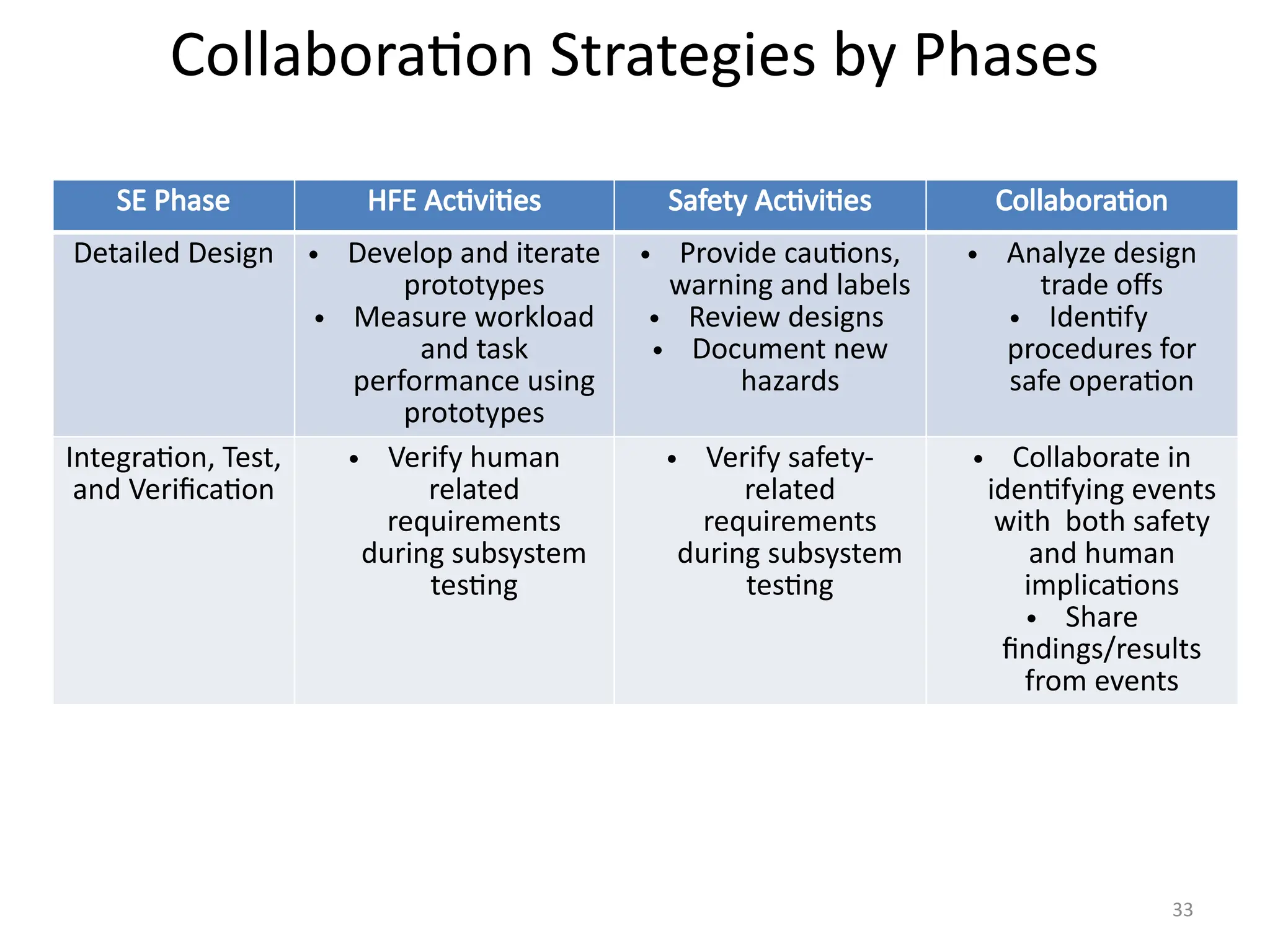
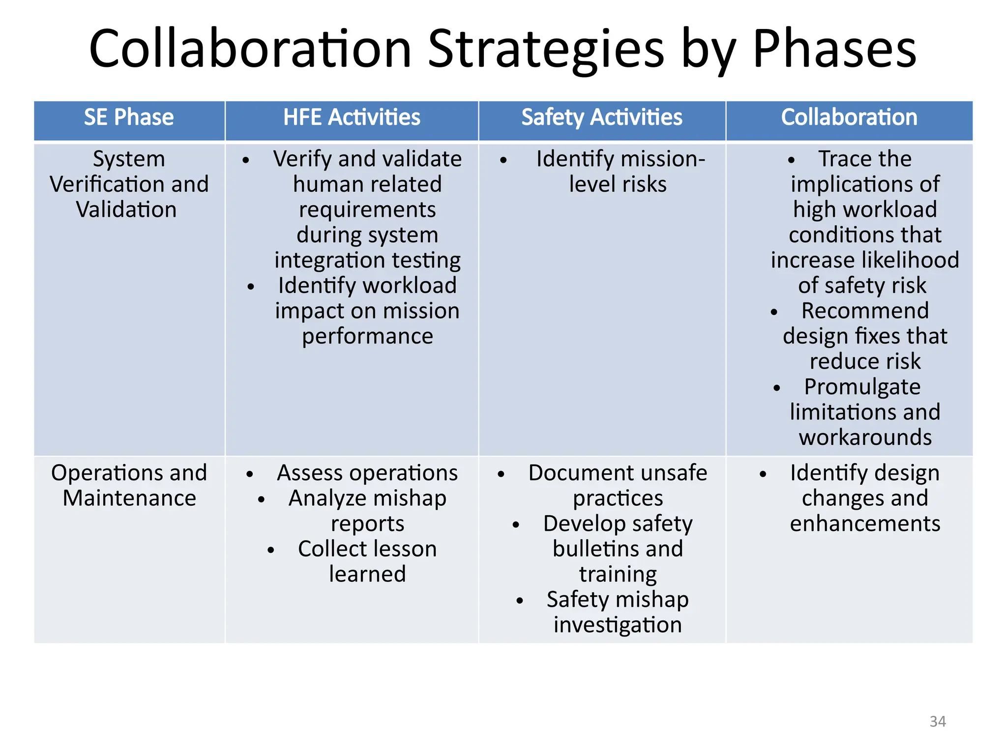
Human Factors and Safety
Collaboration
Mike Goings
Lisa Chavez
BCI, Inc.
2
Presentation Outline
• Difference Between Human Factors and Human
Systems Integration
• What is Human Factors?
• Why Human Factors?
• Human Factors Methods
• How to Apply Human Factors
• Safety and Human Factors
– Swiss Cheese Model
– Physical Human Factors Example
– Cognitive and Physical HF Example: Alerts
– Safety and Human Factors Collaboration
3
Difference Between Human Factors
Engineering and Human Systems Integration
• Human Factors ≠ Human Systems Integration
– Same with other HSI domains (e.g., safety ≠ HSI)
• Human Systems Integration (HSI) is a
management and technical (i.e., systems
engineering) discipline that evaluates tradeoffs
between the seven domains: Manpower,
Personnel, and Training; Safety/Health; Human
Factors, Habitability, and Survivability
• Infographic developed by Dr. Sae Schatz Adobe Acrobat
Document
4
What is Human Factors?
• Applying knowledge of human individual and team behavior,
environment, and mental and physical characteristics for the
design of systems, products, or services
• Utilizes rigorous methods to analyze tasks, gather data, and
prioritize actionable findings to help decision makers
develop efficient and highly useable systems
5
What is Human Factors? Whole System Focus
Based in part on a graphic from: http
://www.alcoa.com/sustainability/en/info_page/safety.asp
6
Why Human Factors?
• Improving safety, procedures, training, and
user interaction with equipment, tools, and
products.
7
Based in part on a graphic from http
://humanisticsystems.com/2014/09/27/systems-thinking-for-safety-ten-p
rinciples
/
8
Select and tailor methods to problem
Understand constraints and decision
maker needs and priorities
Refine, as necessary
Deliver Data-Driven Results
Execute appropriate method
Collect and Analyze Data
How to Apply Human Factors?
Evaluate
Your Design,
Product or
Services
Reports prioritizing
recommendations based
needs & identifying
improvements to:
• Implement now
• Implement later
• Implement when/if
cost & feasibility permit
9
SAFETY AND HUMAN FACTORS
10
Hierarchy of Hazard Control
11
Swiss Cheese Model
12
Swiss Cheese Model
• Active failures are acts of slips, lapses,
fumbles, mistakes, and procedural violations
committed by people in direct contact with
system.
• Latent conditions are issues that reside in a
system and organization and create error
conditions (e.g., time pressure, poorly
designed interfaces, fatigue).
13
PHYSICAL HUMAN FACTORS
EXAMPLE
14
Physical Human Factors
• LCS 2 Decoy Loading
– Issue: The design of the
decoy flare launcher did
not take into account the
warfighter’s task of
loading the weapon
system
– Redesign: Increase cost
to the U.S. Navy
15
Physical Human Factors
Human: Working posture and
muscular strain
Organizational: Not enforcing safe procedures
Environmental: Lack of proper
means to secure personnel
Human error
16
Physical Human Factors
• LCS 2 Decoy Loading
– Define equipment
• Weight and length of flare
– 65 lbs, 4ft long
• Position of flare chambers
– Define users’ tasks
– Define environment,
constraints, and possible
hazards
• Potential for muscular strain
• Potential for falling overboard
– Design equipment
– Develop procedures
17
Physical Human Factors
18
COGNITIVE AND PHYSICAL HF
EXAMPLE: ATTENTION BAR AND ALERTS
19
Primary Display
20
Three Part Attention Bar on Primary Display
• The Attention Bar is displayed as a
vertical strip between the TACSIT and
Close Control Area.
• Attention Bar provides "at-a-glance"
indications and is divided into three
segments
• Segment 1: Identification
• Segment 2: System Status
• Segment 3: Alerts
• Red and flashing is used for high
priority action alerts
• Action alerts require the operator to
review the text details in the alert
review area on the lower part of the
console.
• When the appropriate action is
taken the red and flashing is
removed.
21
Identification Attention Bar - Top Third
• For operators executing identification
tasks, the color of this attention bar
indicates there are pending ID Conflict
Alerts.
• Red - Indicates an ID Conflict Alert
is in the queue regarding an
upgrade or downgrade.
• Gray - Indicates no pending ID
Conflict Alerts.
• There are specific operators that
perform majority of identification
tasks.
• Decision makers do some identification
and serve as redundant checks on
identification done by lower level
operators.
22
System Status Attention Bar – Middle Third
• The System Status is green if all equipment is
operable.
• The System Status flashes yellow or red for
degradations or inoperable equipment status
• Operators are cued by a flashing status bar.
• The flashing indicator bar cues the operator to
bring up the System Status window for detailed
equipment information
• Selected operators that are impacted by specific
equipment problems.
• The System Status bar shows gray for operators
not affected by the specific equipment
• Once the operator has viewed the applicable
equipment status window, the Equipment Status
bar stops flashing and turns gray.
• Typically, lower level operators monitor equipment
status with more frequency than decision makers.
23
Alert Status Attention Bar –Bottom Third
• Depending on whether or not the
operator is a decision maker or lower
level operator – alerts are tailored to
that role.
• Red (blinking) - Pending alert with
priority 1 or 2.
• Red (steady) – Pending alert with
priority 3.
• Yellow (steady) – No high priority
alerts, but there are pending medium
alerts with priority 4, 5, or 6.
• Gray – No pending alerts with
medium or high priority, but there
are pending alerts with priority 7 or
8.
24
Reviewing Alert Details
25
Alert Display Area
26
Complexity, Color Coding & Space Allocation
• Single alert bar design chosen to accommodate different operator
roles: decision makers and lower level operators
– Maximizes space for tactical map and close control readout for track
information
– Loss of diagnostic information on the primary screen
• Experienced operators report :
– “Ignoring” red color coding and flashing due to frequency
– For high priority action alerts, text is read on a separate window to
understand the action to perform to dismiss the alert (stop flashing and
red on the attention bar)
– Yellow color coding for medium alerts applies for moderate level of
importance – yellow and blinking isn’t meaningful and intuitive
• Information alerts (coded yellow and that may be flashing) will need to be
read on the larger alert review area and then prioritized based on operator role
and current task load/context
27
Alert Design Considerations
• Hierarchy of importance
• Salience
• Operators’ tasks
• Information channel and
conflict
• Field of view
• Environment
• Auditory detectability
• Tone vs. Speech
• Visual salience
• Number of alerts
• Tone and pulse
• Location of alerts
28
SAFETY AND HUMAN FACTORS
COLLABORATION
29
Rationale for Collaboration
• Many issues are both human factors and safety related
– Making tradeoffs that benefit the user requires analysis
from both domains
• Safety and HF practitioners have different viewpoints
but shared goal of safe and effective operation
• For HF practitioners analysis that a human factors
issues to safety hazard results in:
– Elevated risk assessment
– Increased the likelihood that safety concerns are designed
out to begin with, or
– Increased likelihood that issue will be fixed in a future build
30
Collaboration Strategies
• Safety and Human Factors Engineers SHOULD work
together on design solutions and the evaluation of risk
• Recognize that the human is an integral part of the
system and has inherent physical and cognitive
capabilities and limitations
• Physical considerations include
– Anthropometry
– Impact of clothing, Personal Protective Equipment (PPE), and gear (e.g.,
backpack)
– Impact of environment (lighting, temperature, noise, vibration)
– Body posture and movement
– Vision (use of color, distance of information, font type, screen resolution)
• Cognitive considerations include
– Presentation of information (information grouping and categorization)
– Memory limitations
– Distractions
31
Collaboration Strategies by System Engineering
Phases
Middle Late
32
Collaboration Strategies by Phases
SE Phase HFE Activities Safety Activities Collaboration Activities
Concept of
Operations
• Analyze tasks,
environment, and
operational
constraints
• Define
representative
users
• Identify potential
hazards
• Define scenarios
that may lead to
hazardous
conditions
Requirements
and
Architecture
• Develop
requirements to
accommodate
human capabilities
• Evaluate
requirements with
safety impact
• Develop
requirements to
mitigate hazards
• Review
requirements that
specify operator
tasks or imply
human
performance
• Specify
requirements that
lower hazard risk
index
• Advocate for
rigorous verification
method for safety
and human factors
requirements
33
Collaboration Strategies by Phases
SE Phase HFE Activities Safety Activities Collaboration
Detailed Design • Develop and iterate
prototypes
• Measure workload
and task
performance using
prototypes
• Provide cautions,
warning and labels
• Review designs
• Document new
hazards
• Analyze design
trade offs
• Identify
procedures for
safe operation
Integration, Test,
and Verification
• Verify human
related
requirements
during subsystem
testing
• Verify safety-
related
requirements
during subsystem
testing
• Collaborate in
identifying events
with both safety
and human
implications
• Share
findings/results
from events
34
Collaboration Strategies by Phases
SE Phase HFE Activities Safety Activities Collaboration
System
Verification and
Validation
• Verify and validate
human related
requirements
during system
integration testing
• Identify workload
impact on mission
performance
• Identify mission-
level risks
• Trace the
implications of
high workload
conditions that
increase likelihood
of safety risk
• Recommend
design fixes that
reduce risk
• Promulgate
limitations and
workarounds
Operations and
Maintenance
• Assess operations
• Analyze mishap
reports
• Collect lesson
learned
• Document unsafe
practices
• Develop safety
bulletins and
training
• Safety mishap
investigation
• Identify design
changes and
enhancements
35
Special Thanks
• Special thanks to the DC Chapter of the Int.
System Safety Society for this opportunity.
• Special thanks to John Murgatroyd and Jason
Green for providing examples and your time.
• Special thanks to Eric Stohr, John Winters, and
Fred Germond for your valuable input.
36
References
• Hierarchy of Hazard Controls". NYCOSH.
Retrieved 2012-04-11.
– http://
nycosh.org/wp-content/uploads/2014/10/hierarc
hy-of-controls-Bway-letterhead.pdf
• Reason J. Human error. New York: Cambridge
University Press; 1990.

Human Factors & safety collaboration .pptx

  • 1.
    Human Factors andSafety Collaboration Mike Goings Lisa Chavez BCI, Inc.
  • 2.
    2 Presentation Outline • DifferenceBetween Human Factors and Human Systems Integration • What is Human Factors? • Why Human Factors? • Human Factors Methods • How to Apply Human Factors • Safety and Human Factors – Swiss Cheese Model – Physical Human Factors Example – Cognitive and Physical HF Example: Alerts – Safety and Human Factors Collaboration
  • 3.
    3 Difference Between HumanFactors Engineering and Human Systems Integration • Human Factors ≠ Human Systems Integration – Same with other HSI domains (e.g., safety ≠ HSI) • Human Systems Integration (HSI) is a management and technical (i.e., systems engineering) discipline that evaluates tradeoffs between the seven domains: Manpower, Personnel, and Training; Safety/Health; Human Factors, Habitability, and Survivability • Infographic developed by Dr. Sae Schatz Adobe Acrobat Document
  • 4.
    4 What is HumanFactors? • Applying knowledge of human individual and team behavior, environment, and mental and physical characteristics for the design of systems, products, or services • Utilizes rigorous methods to analyze tasks, gather data, and prioritize actionable findings to help decision makers develop efficient and highly useable systems
  • 5.
    5 What is HumanFactors? Whole System Focus Based in part on a graphic from: http ://www.alcoa.com/sustainability/en/info_page/safety.asp
  • 6.
    6 Why Human Factors? •Improving safety, procedures, training, and user interaction with equipment, tools, and products.
  • 7.
    7 Based in parton a graphic from http ://humanisticsystems.com/2014/09/27/systems-thinking-for-safety-ten-p rinciples /
  • 8.
    8 Select and tailormethods to problem Understand constraints and decision maker needs and priorities Refine, as necessary Deliver Data-Driven Results Execute appropriate method Collect and Analyze Data How to Apply Human Factors? Evaluate Your Design, Product or Services Reports prioritizing recommendations based needs & identifying improvements to: • Implement now • Implement later • Implement when/if cost & feasibility permit
  • 9.
  • 10.
  • 11.
  • 12.
    12 Swiss Cheese Model •Active failures are acts of slips, lapses, fumbles, mistakes, and procedural violations committed by people in direct contact with system. • Latent conditions are issues that reside in a system and organization and create error conditions (e.g., time pressure, poorly designed interfaces, fatigue).
  • 13.
  • 14.
    14 Physical Human Factors •LCS 2 Decoy Loading – Issue: The design of the decoy flare launcher did not take into account the warfighter’s task of loading the weapon system – Redesign: Increase cost to the U.S. Navy
  • 15.
    15 Physical Human Factors Human:Working posture and muscular strain Organizational: Not enforcing safe procedures Environmental: Lack of proper means to secure personnel Human error
  • 16.
    16 Physical Human Factors •LCS 2 Decoy Loading – Define equipment • Weight and length of flare – 65 lbs, 4ft long • Position of flare chambers – Define users’ tasks – Define environment, constraints, and possible hazards • Potential for muscular strain • Potential for falling overboard – Design equipment – Develop procedures
  • 17.
  • 18.
    18 COGNITIVE AND PHYSICALHF EXAMPLE: ATTENTION BAR AND ALERTS
  • 19.
  • 20.
    20 Three Part AttentionBar on Primary Display • The Attention Bar is displayed as a vertical strip between the TACSIT and Close Control Area. • Attention Bar provides "at-a-glance" indications and is divided into three segments • Segment 1: Identification • Segment 2: System Status • Segment 3: Alerts • Red and flashing is used for high priority action alerts • Action alerts require the operator to review the text details in the alert review area on the lower part of the console. • When the appropriate action is taken the red and flashing is removed.
  • 21.
    21 Identification Attention Bar- Top Third • For operators executing identification tasks, the color of this attention bar indicates there are pending ID Conflict Alerts. • Red - Indicates an ID Conflict Alert is in the queue regarding an upgrade or downgrade. • Gray - Indicates no pending ID Conflict Alerts. • There are specific operators that perform majority of identification tasks. • Decision makers do some identification and serve as redundant checks on identification done by lower level operators.
  • 22.
    22 System Status AttentionBar – Middle Third • The System Status is green if all equipment is operable. • The System Status flashes yellow or red for degradations or inoperable equipment status • Operators are cued by a flashing status bar. • The flashing indicator bar cues the operator to bring up the System Status window for detailed equipment information • Selected operators that are impacted by specific equipment problems. • The System Status bar shows gray for operators not affected by the specific equipment • Once the operator has viewed the applicable equipment status window, the Equipment Status bar stops flashing and turns gray. • Typically, lower level operators monitor equipment status with more frequency than decision makers.
  • 23.
    23 Alert Status AttentionBar –Bottom Third • Depending on whether or not the operator is a decision maker or lower level operator – alerts are tailored to that role. • Red (blinking) - Pending alert with priority 1 or 2. • Red (steady) – Pending alert with priority 3. • Yellow (steady) – No high priority alerts, but there are pending medium alerts with priority 4, 5, or 6. • Gray – No pending alerts with medium or high priority, but there are pending alerts with priority 7 or 8.
  • 24.
  • 25.
  • 26.
    26 Complexity, Color Coding& Space Allocation • Single alert bar design chosen to accommodate different operator roles: decision makers and lower level operators – Maximizes space for tactical map and close control readout for track information – Loss of diagnostic information on the primary screen • Experienced operators report : – “Ignoring” red color coding and flashing due to frequency – For high priority action alerts, text is read on a separate window to understand the action to perform to dismiss the alert (stop flashing and red on the attention bar) – Yellow color coding for medium alerts applies for moderate level of importance – yellow and blinking isn’t meaningful and intuitive • Information alerts (coded yellow and that may be flashing) will need to be read on the larger alert review area and then prioritized based on operator role and current task load/context
  • 27.
    27 Alert Design Considerations •Hierarchy of importance • Salience • Operators’ tasks • Information channel and conflict • Field of view • Environment • Auditory detectability • Tone vs. Speech • Visual salience • Number of alerts • Tone and pulse • Location of alerts
  • 28.
    28 SAFETY AND HUMANFACTORS COLLABORATION
  • 29.
    29 Rationale for Collaboration •Many issues are both human factors and safety related – Making tradeoffs that benefit the user requires analysis from both domains • Safety and HF practitioners have different viewpoints but shared goal of safe and effective operation • For HF practitioners analysis that a human factors issues to safety hazard results in: – Elevated risk assessment – Increased the likelihood that safety concerns are designed out to begin with, or – Increased likelihood that issue will be fixed in a future build
  • 30.
    30 Collaboration Strategies • Safetyand Human Factors Engineers SHOULD work together on design solutions and the evaluation of risk • Recognize that the human is an integral part of the system and has inherent physical and cognitive capabilities and limitations • Physical considerations include – Anthropometry – Impact of clothing, Personal Protective Equipment (PPE), and gear (e.g., backpack) – Impact of environment (lighting, temperature, noise, vibration) – Body posture and movement – Vision (use of color, distance of information, font type, screen resolution) • Cognitive considerations include – Presentation of information (information grouping and categorization) – Memory limitations – Distractions
  • 31.
    31 Collaboration Strategies bySystem Engineering Phases Middle Late
  • 32.
    32 Collaboration Strategies byPhases SE Phase HFE Activities Safety Activities Collaboration Activities Concept of Operations • Analyze tasks, environment, and operational constraints • Define representative users • Identify potential hazards • Define scenarios that may lead to hazardous conditions Requirements and Architecture • Develop requirements to accommodate human capabilities • Evaluate requirements with safety impact • Develop requirements to mitigate hazards • Review requirements that specify operator tasks or imply human performance • Specify requirements that lower hazard risk index • Advocate for rigorous verification method for safety and human factors requirements
  • 33.
    33 Collaboration Strategies byPhases SE Phase HFE Activities Safety Activities Collaboration Detailed Design • Develop and iterate prototypes • Measure workload and task performance using prototypes • Provide cautions, warning and labels • Review designs • Document new hazards • Analyze design trade offs • Identify procedures for safe operation Integration, Test, and Verification • Verify human related requirements during subsystem testing • Verify safety- related requirements during subsystem testing • Collaborate in identifying events with both safety and human implications • Share findings/results from events
  • 34.
    34 Collaboration Strategies byPhases SE Phase HFE Activities Safety Activities Collaboration System Verification and Validation • Verify and validate human related requirements during system integration testing • Identify workload impact on mission performance • Identify mission- level risks • Trace the implications of high workload conditions that increase likelihood of safety risk • Recommend design fixes that reduce risk • Promulgate limitations and workarounds Operations and Maintenance • Assess operations • Analyze mishap reports • Collect lesson learned • Document unsafe practices • Develop safety bulletins and training • Safety mishap investigation • Identify design changes and enhancements
  • 35.
    35 Special Thanks • Specialthanks to the DC Chapter of the Int. System Safety Society for this opportunity. • Special thanks to John Murgatroyd and Jason Green for providing examples and your time. • Special thanks to Eric Stohr, John Winters, and Fred Germond for your valuable input.
  • 36.
    36 References • Hierarchy ofHazard Controls". NYCOSH. Retrieved 2012-04-11. – http:// nycosh.org/wp-content/uploads/2014/10/hierarc hy-of-controls-Bway-letterhead.pdf • Reason J. Human error. New York: Cambridge University Press; 1990.