![INTERNATIONAL JOURNAL OF ELECTRONICS AND
International Journal of Electronics and Communication Engineering & Technology (IJECET), ISSN
0976 – 6464(Print), ISSN 0976 – 6472(Online) Volume 3, Issue 3, October- December (2012), © IAEME
COMMUNICATION ENGINEERING & TECHNOLOGY (IJECET)
ISSN 0976 – 6464(Print)
ISSN 0976 – 6472(Online)
Volume 3, Issue 3, October- December (2012), pp. 103-111 IJECET
© IAEME: www.iaeme.com/ijecet.asp
Journal Impact Factor (2012): 3.5930 (Calculated by GISI) ©IAEME
www.jifactor.com
IMPLEMENTATION & PERFORMANCE ANALYSIS OF CORDIC IN
OFDM BASED WLAN SYSTEM USING VHDL
Mr. Sandeep Bidwai1, Mrs. Saylee S. Bidwai2, Prof. Dr. S.P. Patil3 ,Mrs. Sunita S. Shinde4
ABSTRACT
This paper is focused on the implementation of CO-ordinate Rotation Digital Ccomputer
(CORDIC) algorithm in wireless Local Area Network (WLAN) receiver. The primary task is
to create a VHDL description for CORDIC vector rotation algorithm. The basic work has
been carried out in MATLAB. The VHDL implementation of the CORDIC algorithm is based
on the results obtained from the MATLAB’s simulation environment. The main task is to
make the calculated angle value point the vector to the same constellation point, not to nearest
one. This is the cause that determines the required accuracy of the angle calculation. It takes
the closest vectors in the signal constellation as input. CORDIC moduld to which the
calculated angle is given as input to comput the sine and cosine functions using Simulink.
Last Step includes the analysis of CORDIC algorithm using VHDL and the simulation results.
Key Words: CORDIC, VHDL, WLAN
I INTRODUCTION
The COordinate Rotation DIgital Computer algorithm was developed by Volder in
1959.[1] Additional theoratical work has been carried by Walther[2] in 1971. All
trigonometric functions can be computed using vector rotation. It rotates the vector,
step−by−step, with a given angle. Additional theoretical work has been done by Walther in
1971. The main principle of CORDIC are calculations based on shift−registers and adders
instead of multiplications, what saves much hardware resources. CORDIC is used for polar to
rectangular and rectangular to polar conversions and also for calculation of trigonometric
functions, vector magnitude and in some transformations, like discrete Fourier transform
(DFT) or discrete cosine transform (DCT). In particular case, the CORDIC algorithm is used
in Wireless Local Area Network (WLAN) by receivers.
This paper is organized in five sections. Section II contains the block diagram of
CORDIC algorithm, it’s architecture. Section III includes the OFDM Based WLAN
transmitter design to generate the phase angle. CORDIC moduld to which the calculated angle
103](https://image.slidesharecdn.com/implementationperformanceanalysisofcordic-121220232015-phpapp01/85/Implementation-performance-analysis-of-cordic-1-320.jpg)
![International Journal of Electronics and Communication Engineering & Technology (IJECET), ISSN
0976 – 6464(Print), ISSN 0976 – 6472(Online) Volume 3, Issue 3, October- December (2012), © IAEME
theta is given as input to comput the sine and cosine functions using Simulink with related
CORDIC equations. Section IV deals with the varification process in which 2QN format data
has been varified whether CORDIC module analysed in VHDL producing the same length of
data. Section V includes the simulation results. Few important aspects are highlighted in the
paper. To cover all aspects is beyound the scope of this paper.
II. BLOCK DIAGRAM OF CORDIC
Figure 1 represents the block diagram of conventional CORDIC algorithm , based on ripple
carry adders or sub tractors
Figure.1 Block diagram of CORDIC [3]
An adder/subtractor (A/S), depending on a selection input, performs an addition or a
subtraction. This input indicates whether an operand is negative. The basic cell of A/S is
decomposed by two functions with 4 bits input each. One of them is for calculating the output
and another to transmit the carry. According to this an N−bit A/S can fit in (2N+1)/2 CLBs
(configurable logic block). The additional half CLB is required for introducing the least
significant bit (LSB) one in case of the substraction. The critical path here is indicated by the
ripple carry propagation and the routing delay of the A/S wire. This net has a fan−out of 2N in
this case. It decreases the performance of the circuit and it is the main disadvantage of
conventional CORDIC implementations. As the solution to this, redundant arithmetic could
be used to increase the speed of the CORDIC. Implementation avoids the carry propagation
from the LSB to the most significant bit (MSB), due to its carry−free property. Redundant
arithmetic is good to accelerate those operations, which have a long propagation delay. On the
other hand redundant arithmetic also has some disadvantages. For example, it is impossible to
detect the sign of a redundant number without checking all the digits which expects a
propagation from the MSB to the LSB. Another problem, that the redundant arithmetic uses
digit set {−1,0,1}, and needs more hardware resources to execute simple tasks, than the
104](https://image.slidesharecdn.com/implementationperformanceanalysisofcordic-121220232015-phpapp01/85/Implementation-performance-analysis-of-cordic-2-320.jpg)
![International Journal of Electronics and Communication Engineering & Technology (IJECET), ISSN
0976 – 6464(Print), ISSN 0976 – 6472(Online) Volume 3, Issue 3, October- December (2012), © IAEME
conventional one which uses digit set {−1,1}. According to results of the research, the
redundant arithmetic is more accurate, but it needs much more hardware than the
conventional arithmetic and for this reason conventional arithmetic has been used in this
work. [3] Similar kind of functionalities
III OFDM BASED WLAN TRANSMITTER
Figure 2 OFDM based WLAN Transmitter
Figure 2 shows the Orthogonal Frequency Division Multiplexing (OFDM) based Wirless
LAN transmitter designed in MATLAB simulink . The basic objective is to provide the angle
theta to the CORDIC block for further processing. The signal coming from multipath fadding
and Added White Gaussian Nnoise (AWGN) has magnitude and phase. The magnitude is
terminated and the angle theta is provided in the form of .mat file which is interm connected
to the next CORDIC environment shown in Figure 2. The data source used here is Bernoulli
Binary source which is connected to RS encoder for encoding the generated signal. The
modulation technique used here is Quadrature Phase shift Keying (QPSK) and mapping is
done. The cyclic prefix is added with the signal. Training bits are inserted in training block
which is next converted from parallel to serial data. This data is given to multipath fadding
channel along with AWGN.[4]
Figure 3 CORDIC module to implement Sine and Cosine (MATLAB Design)
105](https://image.slidesharecdn.com/implementationperformanceanalysisofcordic-121220232015-phpapp01/85/Implementation-performance-analysis-of-cordic-3-320.jpg)
![International Journal of Electronics and Communication Engineering & Technology (IJECET), ISSN
0976 – 6464(Print), ISSN 0976 – 6472(Online) Volume 3, Issue 3, October- December (2012), © IAEME
Above figure 3 shows the CORDIC module for Sine and cosine functions using Embedded
MATLAB function block. The CORDIC module has set with inbuilt sine and cosine functions
and processed with standard reference sine and sine signals and compaired. In the output it is
clear that the nature of sine and cosine signals are near about same. Thus we have varified the
performance of prepared CORDIC module with standard
The basic equations for vector rotation are
x ‘ = cos(θ)[x-ytan(θ)]
y ‘ = cos(θ)[y+xtan(θ)]
θ=Rotation angle. (1)
where x and y are original coordinates before rotation and x’ and y’ are the coordinates after
rotation. This equatationcan be simplified by assuming that the tangent is a power of 2.
tan(θ) = + 2(-n) (2)
Then any angle of rotation can be obtained by performing successive smaller rotations. This
assumption help us to write equation (1) in the form of iterative operations.
Xn+1 = Kn [xn-yndn 2(-n)]
Yn+1 = Kn [yn+xndn 2(-n)]
Zn+1 = zn –dnatan 2(-n) ________
Kn = cos(atan 2 )) = 1 + √1+ 2(-2n)
-n
Dn=+1 (3)
These equations can be used in two different modes: rotation mode and vector mode. In
rotation mode, the input vector rotates by a specific angle. In vector mode, the input vector
rotates to the x axis. [5]
In rotation mode the following equations are used:
Xn+1 = Kn [xn – yndn 2(-n)]
Yn+1 = Kn[yn + xndn 2(-n)]
Zn+1 = zn – dnatan2 (-n)]
Dn=-1 if zn<0,+1otherwise (4)
Result after n iterations can be given as
Xn = Gn[x0cos(θ0) – y0 sine(θ0)]
Yn = Gn [y0cos (θ0) + x0 sine(θ0)]
θn =0 ________
Gn = √1+ 2- 2n (5)
Where G is constant and approaches to 1.647 when n approaches to infinity.
In vector mode the following equations are used:
Xn+1 = Kn [n –yndn 2 (-n)]
Yn+1 = Kn [yn + xndn 2(-n)]
Zn+1 = zn- dn.atan2(-n)
dn=+1,if yn<0, -1 otherwise (6)
results after n iterations can be given as
xn = Gn√ x02 + y02
yn = 0
θn = θ0 + atan (y0/x0)
106](https://image.slidesharecdn.com/implementationperformanceanalysisofcordic-121220232015-phpapp01/85/Implementation-performance-analysis-of-cordic-4-320.jpg)


![International Journal of Electronics and Communication Engineering & Technology (IJECET), ISSN
0976 – 6464(Print), ISSN 0976 – 6472(Online) Volume 3, Issue 3, October- December (2012), © IAEME
REFERENCES
[1] Volder J.E., "The CORDIC Trigonometric Computing Technique", IRE Trans. Electronic
Computers, vol. EC−8, pp 330−334, 1959.
[2] Walter J.S. "A Unified Algorithm for Elementary Functions", Proc. Spring. Joint Comput.
Conference, vol. 38, pp 379−385, Jul. 1992.
[3]Anastasia Lashko, Oleg Zakaznov, “VHDL implementation of CORDIC algorithm for
wireless LAN”, Master thesis performed in Electronics Systems,
LiTH−ISY−EX−3515,Linköping, 2004.
[4] Sandell M., van de Beek J.−J., Börjesson P.: "Timing and Frequency Synchronization in
OFDM Systems Using the Cyclic Prefix", pp 16−19, Essen, Germany, Desember 1995.
[5] Ray Andraka, “A Survey of CORDIC algorithms for FPGA based computers”,andraka
consulting group, inc. ACM 0-89791-978-5/98/01, page no. 3,1998.
ABOUT AUTHOR(S)
Mr. Sandeep S. Bidwai,Working as a Asst. Professor in E & TC Dept, at
ADCET Ashta, Dist- Sangli (MS- INDIA). Completed his BE (E & TC) from
B.A.M. University Aurangabad (MS) & ME (Electronics)from Sivaji
University Kolhapur (MS). He has 6 Yrs of teaching experience & field of
interest – VLSI design & Wireless Communication. Life member of ISTE.
Mrs. Saylee S. Bidwai, Working as a Asst. Professor in E &TC Dept, at ADCET
Ashta, Dist- Sangli (MS- INDIA). Completed her BE (Electronics) from SRT
university Nanded (MS) & ME (Electronics)from Shivaji University kolhapur (MS).
She has 6.5 Yrs of teaching experience & field of interest – VLSI design. Life
member of ISTE. She has published 2 research papers in International conference
and Journal.
Dr. S.P.Patil,Presently working as Principal Of Karmayogi College of Engg. P
andharpur, (MS- INDIA). He has completed his BE, ME (Electronics) &
PhD from Shivaji University, Kolhapur & He has 27 Years of Teaching &
Administration experience. His areas of interests are Signal processing &
biomedical engineering. He has published 5 Enginieering Books. He has published
research papers in 36 conferences and 8 journals. Life member of ISTE, IETE.
Mrs. Sunita S. Shinde received the Bachelor’s degree,
Masters degree in Electronics Engineering from Shivaji
University, Kolhapur, Maharashtra. She is pursuing Ph.D. at VTU Belgaum.
She is having 14 years teaching experience. Her field of interest is Wireless
communication, Adhoc Networks. She is a life member of ISTE. She wrote
three books on Computer Networks.
111](https://image.slidesharecdn.com/implementationperformanceanalysisofcordic-121220232015-phpapp01/85/Implementation-performance-analysis-of-cordic-9-320.jpg)
Implementation performance analysis of cordic
- 1. INTERNATIONAL JOURNAL OF ELECTRONICS AND International Journal of Electronics and Communication Engineering & Technology (IJECET), ISSN 0976 – 6464(Print), ISSN 0976 – 6472(Online) Volume 3, Issue 3, October- December (2012), © IAEME COMMUNICATION ENGINEERING & TECHNOLOGY (IJECET) ISSN 0976 – 6464(Print) ISSN 0976 – 6472(Online) Volume 3, Issue 3, October- December (2012), pp. 103-111 IJECET © IAEME: www.iaeme.com/ijecet.asp Journal Impact Factor (2012): 3.5930 (Calculated by GISI) ©IAEME www.jifactor.com IMPLEMENTATION & PERFORMANCE ANALYSIS OF CORDIC IN OFDM BASED WLAN SYSTEM USING VHDL Mr. Sandeep Bidwai1, Mrs. Saylee S. Bidwai2, Prof. Dr. S.P. Patil3 ,Mrs. Sunita S. Shinde4 ABSTRACT This paper is focused on the implementation of CO-ordinate Rotation Digital Ccomputer (CORDIC) algorithm in wireless Local Area Network (WLAN) receiver. The primary task is to create a VHDL description for CORDIC vector rotation algorithm. The basic work has been carried out in MATLAB. The VHDL implementation of the CORDIC algorithm is based on the results obtained from the MATLAB’s simulation environment. The main task is to make the calculated angle value point the vector to the same constellation point, not to nearest one. This is the cause that determines the required accuracy of the angle calculation. It takes the closest vectors in the signal constellation as input. CORDIC moduld to which the calculated angle is given as input to comput the sine and cosine functions using Simulink. Last Step includes the analysis of CORDIC algorithm using VHDL and the simulation results. Key Words: CORDIC, VHDL, WLAN I INTRODUCTION The COordinate Rotation DIgital Computer algorithm was developed by Volder in 1959.[1] Additional theoratical work has been carried by Walther[2] in 1971. All trigonometric functions can be computed using vector rotation. It rotates the vector, step−by−step, with a given angle. Additional theoretical work has been done by Walther in 1971. The main principle of CORDIC are calculations based on shift−registers and adders instead of multiplications, what saves much hardware resources. CORDIC is used for polar to rectangular and rectangular to polar conversions and also for calculation of trigonometric functions, vector magnitude and in some transformations, like discrete Fourier transform (DFT) or discrete cosine transform (DCT). In particular case, the CORDIC algorithm is used in Wireless Local Area Network (WLAN) by receivers. This paper is organized in five sections. Section II contains the block diagram of CORDIC algorithm, it’s architecture. Section III includes the OFDM Based WLAN transmitter design to generate the phase angle. CORDIC moduld to which the calculated angle 103
- 2. International Journal of Electronics and Communication Engineering & Technology (IJECET), ISSN 0976 – 6464(Print), ISSN 0976 – 6472(Online) Volume 3, Issue 3, October- December (2012), © IAEME theta is given as input to comput the sine and cosine functions using Simulink with related CORDIC equations. Section IV deals with the varification process in which 2QN format data has been varified whether CORDIC module analysed in VHDL producing the same length of data. Section V includes the simulation results. Few important aspects are highlighted in the paper. To cover all aspects is beyound the scope of this paper. II. BLOCK DIAGRAM OF CORDIC Figure 1 represents the block diagram of conventional CORDIC algorithm , based on ripple carry adders or sub tractors Figure.1 Block diagram of CORDIC [3] An adder/subtractor (A/S), depending on a selection input, performs an addition or a subtraction. This input indicates whether an operand is negative. The basic cell of A/S is decomposed by two functions with 4 bits input each. One of them is for calculating the output and another to transmit the carry. According to this an N−bit A/S can fit in (2N+1)/2 CLBs (configurable logic block). The additional half CLB is required for introducing the least significant bit (LSB) one in case of the substraction. The critical path here is indicated by the ripple carry propagation and the routing delay of the A/S wire. This net has a fan−out of 2N in this case. It decreases the performance of the circuit and it is the main disadvantage of conventional CORDIC implementations. As the solution to this, redundant arithmetic could be used to increase the speed of the CORDIC. Implementation avoids the carry propagation from the LSB to the most significant bit (MSB), due to its carry−free property. Redundant arithmetic is good to accelerate those operations, which have a long propagation delay. On the other hand redundant arithmetic also has some disadvantages. For example, it is impossible to detect the sign of a redundant number without checking all the digits which expects a propagation from the MSB to the LSB. Another problem, that the redundant arithmetic uses digit set {−1,0,1}, and needs more hardware resources to execute simple tasks, than the 104
- 3. International Journal of Electronics and Communication Engineering & Technology (IJECET), ISSN 0976 – 6464(Print), ISSN 0976 – 6472(Online) Volume 3, Issue 3, October- December (2012), © IAEME conventional one which uses digit set {−1,1}. According to results of the research, the redundant arithmetic is more accurate, but it needs much more hardware than the conventional arithmetic and for this reason conventional arithmetic has been used in this work. [3] Similar kind of functionalities III OFDM BASED WLAN TRANSMITTER Figure 2 OFDM based WLAN Transmitter Figure 2 shows the Orthogonal Frequency Division Multiplexing (OFDM) based Wirless LAN transmitter designed in MATLAB simulink . The basic objective is to provide the angle theta to the CORDIC block for further processing. The signal coming from multipath fadding and Added White Gaussian Nnoise (AWGN) has magnitude and phase. The magnitude is terminated and the angle theta is provided in the form of .mat file which is interm connected to the next CORDIC environment shown in Figure 2. The data source used here is Bernoulli Binary source which is connected to RS encoder for encoding the generated signal. The modulation technique used here is Quadrature Phase shift Keying (QPSK) and mapping is done. The cyclic prefix is added with the signal. Training bits are inserted in training block which is next converted from parallel to serial data. This data is given to multipath fadding channel along with AWGN.[4] Figure 3 CORDIC module to implement Sine and Cosine (MATLAB Design) 105
- 4. International Journal of Electronics and Communication Engineering & Technology (IJECET), ISSN 0976 – 6464(Print), ISSN 0976 – 6472(Online) Volume 3, Issue 3, October- December (2012), © IAEME Above figure 3 shows the CORDIC module for Sine and cosine functions using Embedded MATLAB function block. The CORDIC module has set with inbuilt sine and cosine functions and processed with standard reference sine and sine signals and compaired. In the output it is clear that the nature of sine and cosine signals are near about same. Thus we have varified the performance of prepared CORDIC module with standard The basic equations for vector rotation are x ‘ = cos(θ)[x-ytan(θ)] y ‘ = cos(θ)[y+xtan(θ)] θ=Rotation angle. (1) where x and y are original coordinates before rotation and x’ and y’ are the coordinates after rotation. This equatationcan be simplified by assuming that the tangent is a power of 2. tan(θ) = + 2(-n) (2) Then any angle of rotation can be obtained by performing successive smaller rotations. This assumption help us to write equation (1) in the form of iterative operations. Xn+1 = Kn [xn-yndn 2(-n)] Yn+1 = Kn [yn+xndn 2(-n)] Zn+1 = zn –dnatan 2(-n) ________ Kn = cos(atan 2 )) = 1 + √1+ 2(-2n) -n Dn=+1 (3) These equations can be used in two different modes: rotation mode and vector mode. In rotation mode, the input vector rotates by a specific angle. In vector mode, the input vector rotates to the x axis. [5] In rotation mode the following equations are used: Xn+1 = Kn [xn – yndn 2(-n)] Yn+1 = Kn[yn + xndn 2(-n)] Zn+1 = zn – dnatan2 (-n)] Dn=-1 if zn<0,+1otherwise (4) Result after n iterations can be given as Xn = Gn[x0cos(θ0) – y0 sine(θ0)] Yn = Gn [y0cos (θ0) + x0 sine(θ0)] θn =0 ________ Gn = √1+ 2- 2n (5) Where G is constant and approaches to 1.647 when n approaches to infinity. In vector mode the following equations are used: Xn+1 = Kn [n –yndn 2 (-n)] Yn+1 = Kn [yn + xndn 2(-n)] Zn+1 = zn- dn.atan2(-n) dn=+1,if yn<0, -1 otherwise (6) results after n iterations can be given as xn = Gn√ x02 + y02 yn = 0 θn = θ0 + atan (y0/x0) 106
- 5. International Journal of Electronics and Communication Engineering & Technology (IJECET), ISSN 0976 – 6464(Print), ISSN 0976 – 6472(Online) Volume 3, Issue 3, October- December (2012), © IAEME Gn=√1+ 2(-2n) (7) To calculate the sine and cosine functions, the CORDIC algorithm in rotational mode is used. The initial conditions are: X0= 1/ Gn Y0 = 0 Using these initial conditions equation 5 reduces to Xn = cos (θ0) (8) Yn = sin (θ0) (9) From the above equatations, the angle theta is calculated from the OFDM based WLAN system and given to CORDIC module designed in simulink to implement the trignometric functions like Sine and Cosine. The result of MATLAB code created for phase rotation is as shown in Figure 4 which shows that phase rotation of incomming vectors is shifted to 45 deg.s using CORDIC. The MATLAB code has been created to produce the reference angle in CORDIC fashion. This angle has been given to CORDIC module designed in simulink to get Sine and Cosine. Figure 4 phase rotation using CORDIC The output wave for CORDIC sine-cosine & it’s difference with reference sine-cosine is as shown in following figure.5. It is found that cordic module gives the same output as regular sine-cosine module with small amplitude difference. 107
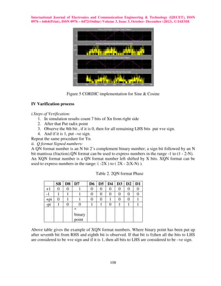
- 6. International Journal of Electronics and Communication Engineering & Technology (IJECET), ISSN 0976 – 6464(Print), ISSN 0976 – 6472(Online) Volume 3, Issue 3, October- December (2012), © IAEME Figure 5 CORDIC implementation for Sine & Cosine IV Varification process i.Steps of Verification: 1. In simulation results count 7 bits of Xn from right side 2. After that Put radix point 3. Observe the 8th bit , if it is 0, then for all remaining LHS bits put +ve sign. 4. And if it is 1, put –ve sign. Repeat the same procedure for Yn. ii. Q format Signed numbers: A QN format number is an N bit 2’s complement binary number; a sign bit followed by an N bit mantissa (fraction).QN format can be used to express numbers in the range -1 to (1 - 2-N). An XQN format number is a QN format number left shifted by X bits. XQN format can be used to express numbers in the range: ( -2X ) to ( 2X - 2(X-N) ). Table 2. 2QN format Phase SB D8 D7 D6 D5 D4 D3 D2 D1 +1 0 0 1 0 0 0 0 0 0 -1 1 1 1 0 0 0 0 0 0 +pi 0 1 1 0 0 1 0 0 1 -pi 1 0 0 1 1 0 1 1 1 ^ binary point Above table gives the example of XQN format numbers. Where binary point has been put up after seventh bit from RHS and eighth bit is observed. If that bit is 0,then all the bits to LHS are considered to be +ve sign and if it is 1, then all bits to LHS are considered to be –ve sign. 108
- 7. International Journal of Electronics and Communication Engineering & Technology (IJECET), ISSN 0976 – 6464(Print), ISSN 0976 – 6472(Online) Volume 3, Issue 3, October- December (2012), © IAEME iii. Verification: Z0 = (1010 0010 0101 0010 1001 0001)2 = (A 2 5 2 9 1)16 = (10637969)10 Therefore, Xn = Sine (Z0) = -0.5 Yn = Cosine (Z0) = 0.8 The results from simulation are….. Xn = 1111 1111 1111 1111 1101 0110 Yn = 1111 1111 1111 1111 0000 0011 Following the procedure for verification, Xn = 1111 1111 1111 1111 1 101 0110 010 1001 + 1 two’s compliment (- 0. 010 1010)2 therefore Xn=( -0.5)10 Similar steps can be follwed for Yn. So that we can conclude as per the CORDIC data format the outputs are in 2QN format and varified using testbenches waveforms in VHDL as shown in Figure 7. V CORDIC- VHDL results Using HDL coder tool box in MATLAB Simulink, the CORDIC model is converted from Simulink into the HDL files in order to varify the performance of CORDIC algorithm in VHDL. The RTL schematic for CORDIC module is as shown in Figure 6. The input length in the form of Z0 is maintained 24 bits. The inputs are applied in the CORDIC formats in 1QN format. And the respective output is observed in 2 QN format by performing the simulation of test benches of the module in Modelsim simultor. Figure 6 CORDIC module in VHDL The inputs given to module in terms of Z0 is in the CORDIC data format. The output is observed in x(n) and y(n) i.e. cosine and sine functions as discussed previously. Figure 6 109
- 8. International Journal of Electronics and Communication Engineering & Technology (IJECET), ISSN 0976 – 6464(Print), ISSN 0976 – 6472(Online) Volume 3, Issue 3, October- December (2012), © IAEME indicates the digital output waveforms from main CORDIC module. As the clock is kept high, the output is observed at xn and yn. Following table 1 shows the device utilization summary. Table 1 Summary of device utilization Device utilization Summary(estimated values) Logic Utilization Used Available Utilization No. of Slices 747 768 97% No. of slices Flip 127 1536 8% Flops No. of 4 input 1435 1536 93% LUTs No. of bonded 77 124 62% IOBs No. of MULT 4 4 100% 18X18s No. of GCLKs 1 8 12% Also the output waveforms after execution of the test bench of the main CORDIC module are shown in figure 6 as the outputs are as xn and yn. The input bit sequence taken is of 24-bits. But as per QN formet of CORDIC, only 7-bits from right hand side have condidered. The value of z0 given as input is in binary & at the time of simulation the values of xn & yn come in the 2Qn format. For verification of results, the values of xn & yn has to be converted back to the binary form. Figure 7 shows the output wave forms of every block in CORDIC module varifying the resepctive outputs of every sub-blocks designed in simulink environment. Figure 7 output wave forms for Main CORDIC module CONCLUSION The CORDIC module designed in MATLAB simulink has more flexibility to implement the trignometric functions like Sine and Cosine. The CORDIC rotations can be used to perform the operations on the given input angle to rotate it to the desired direction with which magnitude and phase can be computed. Finaly the VHDL module varifies the performance of CORDIC module with the help of Modelsim simulator 110
- 9. International Journal of Electronics and Communication Engineering & Technology (IJECET), ISSN 0976 – 6464(Print), ISSN 0976 – 6472(Online) Volume 3, Issue 3, October- December (2012), © IAEME REFERENCES [1] Volder J.E., "The CORDIC Trigonometric Computing Technique", IRE Trans. Electronic Computers, vol. EC−8, pp 330−334, 1959. [2] Walter J.S. "A Unified Algorithm for Elementary Functions", Proc. Spring. Joint Comput. Conference, vol. 38, pp 379−385, Jul. 1992. [3]Anastasia Lashko, Oleg Zakaznov, “VHDL implementation of CORDIC algorithm for wireless LAN”, Master thesis performed in Electronics Systems, LiTH−ISY−EX−3515,Linköping, 2004. [4] Sandell M., van de Beek J.−J., Börjesson P.: "Timing and Frequency Synchronization in OFDM Systems Using the Cyclic Prefix", pp 16−19, Essen, Germany, Desember 1995. [5] Ray Andraka, “A Survey of CORDIC algorithms for FPGA based computers”,andraka consulting group, inc. ACM 0-89791-978-5/98/01, page no. 3,1998. ABOUT AUTHOR(S) Mr. Sandeep S. Bidwai,Working as a Asst. Professor in E & TC Dept, at ADCET Ashta, Dist- Sangli (MS- INDIA). Completed his BE (E & TC) from B.A.M. University Aurangabad (MS) & ME (Electronics)from Sivaji University Kolhapur (MS). He has 6 Yrs of teaching experience & field of interest – VLSI design & Wireless Communication. Life member of ISTE. Mrs. Saylee S. Bidwai, Working as a Asst. Professor in E &TC Dept, at ADCET Ashta, Dist- Sangli (MS- INDIA). Completed her BE (Electronics) from SRT university Nanded (MS) & ME (Electronics)from Shivaji University kolhapur (MS). She has 6.5 Yrs of teaching experience & field of interest – VLSI design. Life member of ISTE. She has published 2 research papers in International conference and Journal. Dr. S.P.Patil,Presently working as Principal Of Karmayogi College of Engg. P andharpur, (MS- INDIA). He has completed his BE, ME (Electronics) & PhD from Shivaji University, Kolhapur & He has 27 Years of Teaching & Administration experience. His areas of interests are Signal processing & biomedical engineering. He has published 5 Enginieering Books. He has published research papers in 36 conferences and 8 journals. Life member of ISTE, IETE. Mrs. Sunita S. Shinde received the Bachelor’s degree, Masters degree in Electronics Engineering from Shivaji University, Kolhapur, Maharashtra. She is pursuing Ph.D. at VTU Belgaum. She is having 14 years teaching experience. Her field of interest is Wireless communication, Adhoc Networks. She is a life member of ISTE. She wrote three books on Computer Networks. 111