SlideShare a Scribd company logo
INPUT/OUTPUT INTERFACES
By
D.Darling Jemima.
Introduction
Embedded Systems talk with the outside world
via peripherals, such as:
• Keyboard
• Displays
• Touch screen
• Discrete IO: General Purpose
Input/Output (GPIO)
• Analog to Digital/Digital to Analog Converters
(ADC/DAC)
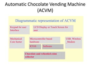
Automatic Chocolate Vending Machine
(ACVM)
Automatic Chocolate Vending Machine
(ACVM)
Digital Camera
Digital Camera
Keyboard Interface
Interfacing to a keyboard using
keyboard controller
Contd…
• Two signals generated by the keyboard controller are
– KBINT(Keyboard interrupt)
– TxD (Transmit Data)
• KBINT is the interrupt from the keyboard controller.
• TxRDY is the transmit buffer ready interrupt that has
been sent from controller to the process.
• RxRDY sends the acknowledgement of the interrupt.
Debouncer
• Bounces create on pressing─ Each bounce creates
a false pulse.
• Keyboard controller has hardware debouncer to
the care of bouncing of a key.
Scan Clock
• Keyboard controller has counter driven by a scan
clock, which continuously increments at certain
rate and scans each key whether that is in
pressed or released state.
keyboard
Encoder
• To encode the keyboard output for a ROM.
• ROM generates the ASCII code output for the
pressed key.
• The code accounts the multiple keys
simultaneously pressed.
• Example, Shift key is also pressed then
generate the code for upper case character.
LCD Display
Interfacing to a LCD display controller
LCD controller ─ A processing element
(single purpose processor)
• 3 bits for E, RS and R/W
• 8 output data.
• One 8-bit port is used for output data for
display.
• Another port is used for 3 bits.
Contd…
• Processing element generates all required signals
for LCD matrix displays (multi-lane).
• Interfaces Eight-bit parallel output port B pins
PB0-PB7, which sends commands for
programming the controller and send data for
display.
• Three control signals IO PC0-PC2 as inputs to LCD
controller.
• PB0 to PB7 8 input/output bits for parallel set of
8 IO bits for commands and data
Control bits
• LCD controller is sent control words and data
words for initialization and programming by
setting the PB0-PB7, PC0 and PC1 outputs for
each word to LCD controller.
Register Select Control bit
• One bit PC0 at an output port for RS(register
select).
• When RS is reset as 0, the PB0-PB7
communicates a control word to control
register of the LCD controller.
• When RS is set as 1, the PB0-PB7
communicates data to LCD controller
R/W (read/write) Control bit
• One bit PC1 at an output port
• Set to 1 when status register of LCD controller
is read using PB0-PB7.
• PC1 is reset to 0 when write into LCD
controller using PB0-PB7 bits.
Enable Control bit
• After setting R/W, RS and data-bits the LCD
controller enables
• Enables by setting 1 at E pin.
• LCD controller connects to one bit PC2 at an
output port for E (enable). There is an interval
depending on the LCD controller, the controller is
disabled. This is because during this interval, the
LCD controller cannot accept instructions or data
through output of other port pins.
CGRAM
• M displayed character ROM addresses.
• M = 128 for 128 ASCII codes.
• For Each distinct ASCII character, there is 64-
bit graphic.
• LCD controller has internal CGRAM (Character
graphic RAM).
• For each ASCII character, 8 bytes are sent from
the ROM to the CGRAM.
Digital Analog Converter
DAC Using a DAC external chip
DAC
• DAC─ PWM(Pulse width modulator) circuit
and an integrator.
• PWM─ internal device in a microcontroller
• A pulse width register (PWR) is programmed
according to a required analog output.
PWM functioning
• A counter/timer device, which generates two
internal- interrupts one on timer overflow and
another after an interval proportional to equal
to PWR.
• On first interrupt, the output becomes 1 and
on second interrupt it becomes 0.
Integrator
• Generates the analog output as per the period
of output = 1 (period between first and
interrupts) compared to total period of output
pulses (period between successive first
interrupts).
Analog Digital Converter
ADC
• Start of conversion pulse generator circuit,
• A sample hold amplifier circuit to hold the
signal constant for the conversion period and
signal conditioner
• Voltage references + and − for providing the
reference for conversion of analog input
ADC Using ADC external chip
Thank you

More Related Content

What's hot (20)

PDF
8259 Programmable Interrupt Controller
abhikalmegh
 
PPTX
Uart
Aditee Apurvaa
 
PPTX
Register organization, stack
Asif Iqbal
 
PPTX
8237 dma controller
Tech_MX
 
PPTX
Arm cortex-m3 by-joe_bungo_arm
Prashant Ahire
 
PPT
I2C Protocol
Anurag Tomar
 
PPTX
Introduction to arm processor
RAMPRAKASHT1
 
PPTX
8051 memory
Mayank Garg
 
PPT
8251 a usart programmable communication interface(1)
divyangpit
 
PPTX
Unit vi (2)
Siva Nageswararao
 
PPS
Interrupts
guest2e9811e
 
PPT
RT linux
SARITHA REDDY
 
PPTX
I2C introduction
SUNODH GARLAPATI
 
PPT
I2 c
sean chen
 
PPTX
Memory Segmentation of 8086
Nikhil Kumar
 
PPTX
ARM Processor
Aniket Thakur
 
DOCX
UNIT-IV .FINITE STATE MACHINES
Dr.YNM
 
PPT
Computer architecture cache memory
Mazin Alwaaly
 
PPTX
UART(universal asynchronous receiver transmitter ) PPT
Sai_praneeth
 
PPTX
MICROCONTROLLER 8051- Architecture & Pin Configuration
AKHIL MADANKAR
 
8259 Programmable Interrupt Controller
abhikalmegh
 
Register organization, stack
Asif Iqbal
 
8237 dma controller
Tech_MX
 
Arm cortex-m3 by-joe_bungo_arm
Prashant Ahire
 
I2C Protocol
Anurag Tomar
 
Introduction to arm processor
RAMPRAKASHT1
 
8051 memory
Mayank Garg
 
8251 a usart programmable communication interface(1)
divyangpit
 
Unit vi (2)
Siva Nageswararao
 
Interrupts
guest2e9811e
 
RT linux
SARITHA REDDY
 
I2C introduction
SUNODH GARLAPATI
 
I2 c
sean chen
 
Memory Segmentation of 8086
Nikhil Kumar
 
ARM Processor
Aniket Thakur
 
UNIT-IV .FINITE STATE MACHINES
Dr.YNM
 
Computer architecture cache memory
Mazin Alwaaly
 
UART(universal asynchronous receiver transmitter ) PPT
Sai_praneeth
 
MICROCONTROLLER 8051- Architecture & Pin Configuration
AKHIL MADANKAR
 

Viewers also liked (20)

PPTX
computer system
AAKASH KUMAR
 
PPSX
P.jeet ppt
Prasunjeet Soni
 
PPT
Input And Output Devices
mrbennett2009
 
PPT
Interface
Siddique Ibrahim
 
PPTX
Computer Systems
corb201
 
PPTX
Input output interface
Christ University
 
PPT
13. Computer Systems Input And Output Architecture
New Era University
 
PPT
Overview of computer system
rozanadiana
 
PPSX
Input, Output and Storage Devices
guest30320a
 
PPTX
Computer Systems - Input, Process, Output
corb201
 
PPTX
Types and components of computer system
mkhisalg
 
PPT
Computer hardware component. ppt
Naveen Sihag
 
PPT
Introduction to Basic Computer Concepts Presentation
Ana Tan
 
PPT
Computer Basics 101 Slide Show Presentation
sluget
 
PPTX
Waves (Notes 1) - CP Physics
kharrison11
 
PPT
Make Wise Real Estate Choices with a Trusted Company
Annabel Brown
 
PDF
10 tips to write engaging facebook posts
Digital Marketing
 
PDF
Hunt capítulo 1_(introdução)
Felipe Hiago
 
PPTX
Connecting the dots - SALTISE 2015
drlautman
 
PPTX
Inscription v. Description
pamlanza
 
computer system
AAKASH KUMAR
 
P.jeet ppt
Prasunjeet Soni
 
Input And Output Devices
mrbennett2009
 
Interface
Siddique Ibrahim
 
Computer Systems
corb201
 
Input output interface
Christ University
 
13. Computer Systems Input And Output Architecture
New Era University
 
Overview of computer system
rozanadiana
 
Input, Output and Storage Devices
guest30320a
 
Computer Systems - Input, Process, Output
corb201
 
Types and components of computer system
mkhisalg
 
Computer hardware component. ppt
Naveen Sihag
 
Introduction to Basic Computer Concepts Presentation
Ana Tan
 
Computer Basics 101 Slide Show Presentation
sluget
 
Waves (Notes 1) - CP Physics
kharrison11
 
Make Wise Real Estate Choices with a Trusted Company
Annabel Brown
 
10 tips to write engaging facebook posts
Digital Marketing
 
Hunt capítulo 1_(introdução)
Felipe Hiago
 
Connecting the dots - SALTISE 2015
drlautman
 
Inscription v. Description
pamlanza
 
Ad

Similar to Input Output Interfaces (20)

PPTX
Basic of Firmware & Embedded Software Programming in C
Kapil Thakar
 
PDF
Microcontroller part 4
Keroles karam khalil
 
PPT
Lcd & keypad
Izwanizam Yahaya
 
PDF
Chap_3L08Emsys3ERealWorldInterfacingPart3KeyBoardLCD.pdf
SenthilKumarP45
 
PPT
Lcd interface with atmega32 avr best.ppt
SoumyaGupta836456
 
DOCX
Keypad interfacing 8051 -NANOCDAC
nanocdac
 
PDF
Lecture mp 7(interface)
Salman Yousafzai
 
PDF
Microcontroladores: El microcontrolador 8051 con LCD 16x2
SANTIAGO PABLO ALBERTO
 
PDF
L14 kb-lcd-interfacing-with-atmega328 p
rsamurti
 
DOC
Unit iii microcontrollers final1
Saritha Reddy
 
PPT
Interfacing ics for microprocessor
THANDAIAH PRABU
 
DOC
REPORT texto braillefinal
ASWATHI K
 
DOCX
Alp lcd
Caleb Joshua
 
PPTX
UNIT 5.pptx
BASKARS53
 
PPTX
Chapter5
Bisrat Girma
 
PPT
jbptunikompp-gdl-syahrul-23476-14-14-inter-y.ppt
lcaimi1
 
PPTX
8051 io interface
Abhinav Shubham
 
PDF
Lcd tutorial
Sujan Heuju
 
PDF
8449972 embedded-systems-and-model-of-metro-train
Jitendra Saroj
 
PPT
AVR Fundamentals
Vinit Vyas
 
Basic of Firmware & Embedded Software Programming in C
Kapil Thakar
 
Microcontroller part 4
Keroles karam khalil
 
Lcd & keypad
Izwanizam Yahaya
 
Chap_3L08Emsys3ERealWorldInterfacingPart3KeyBoardLCD.pdf
SenthilKumarP45
 
Lcd interface with atmega32 avr best.ppt
SoumyaGupta836456
 
Keypad interfacing 8051 -NANOCDAC
nanocdac
 
Lecture mp 7(interface)
Salman Yousafzai
 
Microcontroladores: El microcontrolador 8051 con LCD 16x2
SANTIAGO PABLO ALBERTO
 
L14 kb-lcd-interfacing-with-atmega328 p
rsamurti
 
Unit iii microcontrollers final1
Saritha Reddy
 
Interfacing ics for microprocessor
THANDAIAH PRABU
 
REPORT texto braillefinal
ASWATHI K
 
Alp lcd
Caleb Joshua
 
UNIT 5.pptx
BASKARS53
 
Chapter5
Bisrat Girma
 
jbptunikompp-gdl-syahrul-23476-14-14-inter-y.ppt
lcaimi1
 
8051 io interface
Abhinav Shubham
 
Lcd tutorial
Sujan Heuju
 
8449972 embedded-systems-and-model-of-metro-train
Jitendra Saroj
 
AVR Fundamentals
Vinit Vyas
 
Ad

More from Darling Jemima (6)

PPTX
Introduction to Processor Design and ARM Processor
Darling Jemima
 
DOCX
Never GIve up
Darling Jemima
 
PPTX
Secure group key management based on hyper-sphere
Darling Jemima
 
PPTX
Rope
Darling Jemima
 
PPTX
Application of Dijkstra Algorithm in Robot path planning
Darling Jemima
 
DOCX
Golden bells
Darling Jemima
 
Introduction to Processor Design and ARM Processor
Darling Jemima
 
Never GIve up
Darling Jemima
 
Secure group key management based on hyper-sphere
Darling Jemima
 
Application of Dijkstra Algorithm in Robot path planning
Darling Jemima
 
Golden bells
Darling Jemima
 

Recently uploaded (20)

PPTX
Break Statement in Programming with 6 Real Examples
manojpoojary2004
 
PPTX
Element 7. CHEMICAL AND BIOLOGICAL AGENT.pptx
merrandomohandas
 
PDF
Unified_Cloud_Comm_Presentation anil singh ppt
anilsingh298751
 
PDF
Design Thinking basics for Engineers.pdf
CMR University
 
PPTX
Heart Bleed Bug - A case study (Course: Cryptography and Network Security)
Adri Jovin
 
PPTX
Hashing Introduction , hash functions and techniques
sailajam21
 
PDF
Biomechanics of Gait: Engineering Solutions for Rehabilitation (www.kiu.ac.ug)
publication11
 
PPTX
Solar Thermal Energy System Seminar.pptx
Gpc Purapuza
 
DOCX
CS-802 (A) BDH Lab manual IPS Academy Indore
thegodhimself05
 
PPTX
Shinkawa Proposal to meet Vibration API670.pptx
AchmadBashori2
 
PPT
PPT2_Metal formingMECHANICALENGINEEIRNG .ppt
Praveen Kumar
 
PPTX
Arduino Based Gas Leakage Detector Project
CircuitDigest
 
PPTX
265587293-NFPA 101 Life safety code-PPT-1.pptx
chandermwason
 
PPTX
MPMC_Module-2 xxxxxxxxxxxxxxxxxxxxx.pptx
ShivanshVaidya5
 
PDF
Zilliz Cloud Demo for performance and scale
Zilliz
 
PPTX
GitOps_Without_K8s_Training_detailed git repository
DanialHabibi2
 
PDF
6th International Conference on Machine Learning Techniques and Data Science ...
ijistjournal
 
PPTX
Green Building & Energy Conservation ppt
Sagar Sarangi
 
PDF
MAD Unit - 1 Introduction of Android IT Department
JappanMavani
 
PPTX
Snet+Pro+Service+Software_SNET+Pro+2+Instructions.pptx
jenilsatikuvar1
 
Break Statement in Programming with 6 Real Examples
manojpoojary2004
 
Element 7. CHEMICAL AND BIOLOGICAL AGENT.pptx
merrandomohandas
 
Unified_Cloud_Comm_Presentation anil singh ppt
anilsingh298751
 
Design Thinking basics for Engineers.pdf
CMR University
 
Heart Bleed Bug - A case study (Course: Cryptography and Network Security)
Adri Jovin
 
Hashing Introduction , hash functions and techniques
sailajam21
 
Biomechanics of Gait: Engineering Solutions for Rehabilitation (www.kiu.ac.ug)
publication11
 
Solar Thermal Energy System Seminar.pptx
Gpc Purapuza
 
CS-802 (A) BDH Lab manual IPS Academy Indore
thegodhimself05
 
Shinkawa Proposal to meet Vibration API670.pptx
AchmadBashori2
 
PPT2_Metal formingMECHANICALENGINEEIRNG .ppt
Praveen Kumar
 
Arduino Based Gas Leakage Detector Project
CircuitDigest
 
265587293-NFPA 101 Life safety code-PPT-1.pptx
chandermwason
 
MPMC_Module-2 xxxxxxxxxxxxxxxxxxxxx.pptx
ShivanshVaidya5
 
Zilliz Cloud Demo for performance and scale
Zilliz
 
GitOps_Without_K8s_Training_detailed git repository
DanialHabibi2
 
6th International Conference on Machine Learning Techniques and Data Science ...
ijistjournal
 
Green Building & Energy Conservation ppt
Sagar Sarangi
 
MAD Unit - 1 Introduction of Android IT Department
JappanMavani
 
Snet+Pro+Service+Software_SNET+Pro+2+Instructions.pptx
jenilsatikuvar1
 

Input Output Interfaces

  • 2. Introduction Embedded Systems talk with the outside world via peripherals, such as: • Keyboard • Displays • Touch screen • Discrete IO: General Purpose Input/Output (GPIO) • Analog to Digital/Digital to Analog Converters (ADC/DAC)
  • 8. Interfacing to a keyboard using keyboard controller
  • 9. Contd… • Two signals generated by the keyboard controller are – KBINT(Keyboard interrupt) – TxD (Transmit Data) • KBINT is the interrupt from the keyboard controller. • TxRDY is the transmit buffer ready interrupt that has been sent from controller to the process. • RxRDY sends the acknowledgement of the interrupt.
  • 10. Debouncer • Bounces create on pressing─ Each bounce creates a false pulse. • Keyboard controller has hardware debouncer to the care of bouncing of a key. Scan Clock • Keyboard controller has counter driven by a scan clock, which continuously increments at certain rate and scans each key whether that is in pressed or released state. keyboard
  • 11. Encoder • To encode the keyboard output for a ROM. • ROM generates the ASCII code output for the pressed key. • The code accounts the multiple keys simultaneously pressed. • Example, Shift key is also pressed then generate the code for upper case character.
  • 13. Interfacing to a LCD display controller
  • 14. LCD controller ─ A processing element (single purpose processor) • 3 bits for E, RS and R/W • 8 output data. • One 8-bit port is used for output data for display. • Another port is used for 3 bits.
  • 15. Contd… • Processing element generates all required signals for LCD matrix displays (multi-lane). • Interfaces Eight-bit parallel output port B pins PB0-PB7, which sends commands for programming the controller and send data for display. • Three control signals IO PC0-PC2 as inputs to LCD controller. • PB0 to PB7 8 input/output bits for parallel set of 8 IO bits for commands and data
  • 16. Control bits • LCD controller is sent control words and data words for initialization and programming by setting the PB0-PB7, PC0 and PC1 outputs for each word to LCD controller.
  • 17. Register Select Control bit • One bit PC0 at an output port for RS(register select). • When RS is reset as 0, the PB0-PB7 communicates a control word to control register of the LCD controller. • When RS is set as 1, the PB0-PB7 communicates data to LCD controller
  • 18. R/W (read/write) Control bit • One bit PC1 at an output port • Set to 1 when status register of LCD controller is read using PB0-PB7. • PC1 is reset to 0 when write into LCD controller using PB0-PB7 bits.
  • 19. Enable Control bit • After setting R/W, RS and data-bits the LCD controller enables • Enables by setting 1 at E pin. • LCD controller connects to one bit PC2 at an output port for E (enable). There is an interval depending on the LCD controller, the controller is disabled. This is because during this interval, the LCD controller cannot accept instructions or data through output of other port pins.
  • 20. CGRAM • M displayed character ROM addresses. • M = 128 for 128 ASCII codes. • For Each distinct ASCII character, there is 64- bit graphic. • LCD controller has internal CGRAM (Character graphic RAM). • For each ASCII character, 8 bytes are sent from the ROM to the CGRAM.
  • 22. DAC Using a DAC external chip
  • 23. DAC • DAC─ PWM(Pulse width modulator) circuit and an integrator. • PWM─ internal device in a microcontroller • A pulse width register (PWR) is programmed according to a required analog output.
  • 24. PWM functioning • A counter/timer device, which generates two internal- interrupts one on timer overflow and another after an interval proportional to equal to PWR. • On first interrupt, the output becomes 1 and on second interrupt it becomes 0.
  • 25. Integrator • Generates the analog output as per the period of output = 1 (period between first and interrupts) compared to total period of output pulses (period between successive first interrupts).
  • 27. ADC • Start of conversion pulse generator circuit, • A sample hold amplifier circuit to hold the signal constant for the conversion period and signal conditioner • Voltage references + and − for providing the reference for conversion of analog input
  • 28. ADC Using ADC external chip