IoT
Unit -3
• Embedded computing logic refers to the design and implementation of logic
circuits, algorithms, and software that operate within embedded systems.
Embedded systems are specialized computing systems designed to perform
specific functions within larger systems. They are typically found in devices where
traditional computing systems would be impractical, such as consumer electronics,
automotive systems, industrial machinery, medical devices, and more.
• Embedded computing logic encompasses several key aspects:
• Hardware Design: This involves designing the physical components of the
embedded system, including microcontrollers, microprocessors, sensors, actuators,
memory, and other peripherals. Hardware designers select components based on
factors such as performance, power consumption, size, and cost.
• Software Development: Embedded systems require software to control their
operation and perform specific tasks. This software is typically written in
programming languages like C, C++, or assembly language. Embedded software
developers write code to interface with hardware components, implement
algorithms, manage power consumption, handle communication protocols, and
provide the desired functionality.
• Real-time Processing: Many embedded systems require real-time processing capabilities to
respond to external events within strict timing constraints. Real-time operating systems (RTOS) or
specialized scheduling algorithms are often used to ensure timely execution of tasks.
• Low Power Design: Embedded systems are frequently powered by batteries or other limited power
sources, so optimizing power consumption is crucial. Designers employ techniques such as low-
power hardware components, power management algorithms, and sleep modes to minimize
energy usage.
• Communication Protocols: Embedded systems often need to communicate with other devices or
systems. Designers must select appropriate communication protocols, such as UART, SPI, I2C,
Ethernet, Wi-Fi, Bluetooth, or custom protocols, depending on factors like data rate, range, power
consumption, and compatibility with other devices.
• Security: Security is increasingly important in embedded systems to protect against unauthorized
access, data breaches, and malicious attacks. Designers implement security measures such as
encryption, authentication, access control, secure boot, and intrusion detection to safeguard
embedded systems and the data they handle.
• Testing and Verification: Thorough testing and verification are essential to ensure the reliability,
safety, and functionality of embedded systems. Designers use techniques like simulation,
emulation, hardware-in-the-loop testing, and field testing to validate the design and identify and
resolve any issues.
• Arduino is an open-source electronics platform based on easy-to-use hardware and software. It consists of both
physical programmable circuit boards (often referred to as "Arduino boards") and the software development
environment (Arduino IDE) used to write and upload code to the board. Here's an overview of Arduino boards and
the Arduino IDE:
• Arduino Boards:
• Arduino Uno: One of the most popular Arduino boards, featuring an ATmega328P microcontroller, digital and
analog input/output pins, USB connection for programming and power, and other essential components.
• Arduino Nano: Similar to the Uno but in a smaller form factor, making it suitable for projects with space
constraints.
• Arduino Mega: Equipped with a more powerful ATmega2560 microcontroller and an increased number of
input/output pins compared to the Uno, suitable for more complex projects.
• Arduino Leonardo: Features a different microcontroller (ATmega32U4) with built-in USB communication
capabilities, allowing it to emulate a keyboard or mouse.
• Arduino Due: Powered by a 32-bit ARM Cortex-M3 processor, offering higher performance and more advanced
features compared to the Uno.
• Arduino Pro Mini: Compact and lightweight board designed for embedded applications where space is limited.
• Arduino MKR Series: Arduino boards designed for IoT (Internet of Things) applications, featuring built-in Wi-Fi or
cellular connectivity.
• Arduino Shields: Expansion boards that can be stacked on top of Arduino boards to add additional functionality
such as motor control, communication interfaces (Ethernet, Bluetooth, etc.), displays, sensors, and more.
• Arduino UNO Board
• Power U
• SB- Arduino board can be
• Power USB- Arduino board can be powered by using the USB cable from your computer. All you need to do is
connect the USB cable to the USB connection (1).
• Power (Barrel Jack)- Arduino boards can be powered directly from the AC mains power supply by connecting it to
the Barrel Jack (2).
• Voltage Regulator- The function of the voltage regulator is to control the voltage given to the Arduino board and
stabilize the DC voltages used by the processor and other elements.
• Crystal Oscillator- The crystal oscillator helps Arduino in dealing with time issues. How does Arduino calculate
time? The answer is, by using the crystal oscillator. The number printed on top of the Arduino crystal is
16.000H9H. It tells us that the frequency is 16,000,000 Hertz or 16 MHz.
•
• 5,17. Arduino Reset- You can reset your Arduino board, i.e., start your program from the beginning. You can reset
the UNO board in two ways. First, by using the reset button (17) on the board. Second, you can connect an
external reset button to the Arduino pin labelled RESET (5).
•
• 6,8,9. Pins (3.3, 5, GND, Vin)
• 3.3V (6) − Supply 3.3 output volt
• 5V (7) − Supply 5 output volt
• Most of the components used with Arduino board works fine with 3.3 volt and 5 volt.
• GND (8)(Ground) − There are several GND pins on the Arduino, any of which can be used to ground your circuit.
• Vin (9) − This pin also can be used to power the Arduino board from an external power source, like AC mains
power supply
• Analog pins
• The Arduino UNO board has six analog input pins A0 through A5. These pins can read the signal from an analog
sensor like the humidity sensor or temperature sensor and convert it into a digital value that can be read by the
microprocessor.
•
• 11. Main microcontroller
• Each Arduino board has its own microcontroller (11). You can assume it as the brain of your board. The main IC
(integrated circuit) on the Arduino is slightly different from board to board. The microcontrollers are usually of the
ATMEL Company. You must know what IC your board has before loading up a new program from the Arduino IDE.
This information is available on the top of the IC. For more details about the IC construction and functions, you
can refer to the data sheet.
•
• 12. ICSP pin
• Mostly, ICSP (12) is an AVR, a tiny programming header for the Arduino consisting of MOSI, MISO, SCK, RESET, VCC,
and GND. It is often referred to as an SPI (Serial Peripheral Interface), which could be considered as an
"expansion" of the output. Actually, you are slaving the output device to the master of the SPI bus.
•
• 13. Power LED indicator
• This LED should light up when you plug your Arduino into a power source to indicate that your board is powered
up correctly. If this light does not turn on, then there is something wrong with the connection.
• TX and RX LEDs
• On your board, you will find two labels: TX (transmit) and RX (receive). They
appear in two places on the Arduino UNO board. First, at the digital pins 0 and 1,
to indicate the pins responsible for serial communication. Second, the TX and RX
led (13). The TX led flashes with different speed while sending the serial data. The
speed of flashing depends on the baud rate used by the board. RX flashes during
the receiving process.
•
• 15. Digital I/O
• The Arduino UNO board has 14 digital I/O pins (15) (of which 6 provide PWM
(Pulse Width Modulation) output. These pins can be configured to work as input
digital pins to read logic values (0 or 1) or as digital output pins to drive different
modules like LEDs, relays, etc. The pins labeled “~” can be used to generate PWM.
• 16. AREF
• AREF stands for Analog Reference. It is sometimes, used to set an external
reference voltage (between 0 and 5 Volts) as the upper limit for the analog input
pins.
• Board Details:
• Microcontroller: Arduino boards are typically equipped with microcontrollers from the Atmel AVR
or ARM families. The most common microcontroller used in Arduino boards is the Atmega series,
such as Atmega328P (used in Arduino Uno) or Atmega2560 (used in Arduino Mega).
• Digital and Analog I/O Pins: Arduino boards feature a set of digital input/output (I/O) pins and
analog input pins. These pins can be used to connect sensors, actuators, and other electronic
components to the board.
• Power Supply: Arduino boards can be powered via USB connection, an external power supply, or a
battery. They usually accept a wide range of input voltages, typically 5V or 3.3V.
• Clock Speed: Arduino boards operate at various clock speeds, depending on the specific
microcontroller used. Common clock speeds range from 8 MHz to 16 MHz.
• Memory: Arduino boards have flash memory for storing the uploaded code (program), as well as
SRAM and EEPROM for data storage during program execution.
• Interfaces: Arduino boards may include various interfaces such as USB, UART (serial), SPI, I2C, and
GPIO pins, allowing communication with other devices and peripherals.
• Arduino IDE:
• The Arduino Integrated Development
Environment (IDE) is a cross-platform
application written in Java that provides a
simple and intuitive interface for writing,
compiling, and uploading code to Arduino
boards.
•
Internet of Things Unit 3 notes-Design and Development and Arduino.pptx
• Menu Bar: Gives you access to the tools needed for creating and saving Arduino sketches.
• Verify Button: Compiles your code and checks for errors in spelling or syntax.
• Upload Button: Sends the code to the board that’s connected such as Arduino Uno in this case. Lights on the board will blink rapidly when uploading.
• New Sketch: Opens a new window containing a blank sketch.
• Sketch Name: When the sketch is saved, the name of the sketch is displayed here.
• Open Existing Sketch: Allows you to open a saved sketch or one from the stored examples.
• Save Sketch: This saves the sketch you currently have open.
• Serial Monitor: When the board is connected, this will display the serial information of your Arduino
• Code Area: This area is where you compose the code of the sketch that tells the board what to do.
• Message Area: This area tells you the status on saving, code compiling, errors and more.
• Text Console: Shows the details of an error messages, size of the program that was compiled and additional info.
• Board and Serial Port: Tells you what board is being used and what serial port it’s connected to.
• Here's an overview of its features:
• Code Editor: A text editor with syntax highlighting and auto-indentation for writing Arduino sketches (programs).
• Sketches: Arduino programs are called sketches, written in C or C++ programming languages.
• Library Manager: A built-in library manager allows users to easily install, manage, and include libraries for interfacing with various sensors, actuators,
and communication modules.
• Serial Monitor: A tool for debugging Arduino sketches by displaying messages sent from the Arduino board via the Serial communication interface.
• Board Manager: Allows users to install and manage different board definitions for various Arduino-compatible boards.
• Upload Button: A button to compile and upload the sketch to the connected Arduino board.
• Examples: Provides a collection of example sketches demonstrating different functionalities of Arduino boards and peripherals.
• Tools: Options for selecting the Arduino board, processor, port, and programmer settings.
• Programming with Arduino IDE:
• The Arduino Integrated Development Environment (IDE) is the software used to write, compile, and
upload code to Arduino boards. Here's a basic overview of the programming process:
• Install Arduino IDE: Download and install the Arduino IDE from the official Arduino website
(https://www.arduino.cc/en/software).
• Connect Arduino Board: Connect your Arduino board to your computer using a USB cable.
• Open Arduino IDE: Launch the Arduino IDE software.
• Write Code: Write your Arduino code in the IDE. The code consists of two main functions: setup()
(executed once at the beginning) and loop() (executed repeatedly).
• Verify/Compile Code: Click the "Verify" button (checkmark icon) to compile your code. This checks
for syntax errors and compiles the code into machine-readable instructions.
• Upload Code: Once the code compiles successfully, click the "Upload" button (right arrow icon) to
upload the code to the connected Arduino board.
• Monitor Serial Output (Optional): You can use the Serial Monitor feature in the Arduino IDE to
debug your code and view output messages from the Arduino board

More Related Content

PPTX
Introduction to arduino ppt main
PPT
Introduction to Arduino 16822775 (2).ppt
PDF
PPTX
Lecture 7
PPTX
Introduction to Arduino (Parts of Arduino Microcontroller) .pptx
PPTX
Internet of Things prescribed by University
PPTX
IOT-UNIT 3.pptxaaaasasasasasasaasasasasas
PPTX
ARDUINO OVERVIEW HARDWARE SOFTWARE AND INSTALLATION.pptx
Introduction to arduino ppt main
Introduction to Arduino 16822775 (2).ppt
Lecture 7
Introduction to Arduino (Parts of Arduino Microcontroller) .pptx
Internet of Things prescribed by University
IOT-UNIT 3.pptxaaaasasasasasasaasasasasas
ARDUINO OVERVIEW HARDWARE SOFTWARE AND INSTALLATION.pptx

Similar to Internet of Things Unit 3 notes-Design and Development and Arduino.pptx (20)

PDF
Arduino microcontroller ins and outs with pin diagram
PPTX
By Asst.Prof.D.R.Bhise Electrical Engineering Department Matoshri College of...
PPT
IoT Basics with few Embedded System Connections for sensors
PPTX
Chapter 5 Arduino Microcontroller Systems .pptx
PDF
Report on arduino
PPTX
arduino and its introduction deep dive ppt.pptx
PPTX
This will give the basic introduction to a arduino
PDF
Mechanical engineering jntuk r-23inernet
PDF
ARDUINO OVERVIEW HARDWARE SOFTWARE AND INSTALLATION.pdf
PPTX
Arduino Family
PDF
VERY NICE FOR CSE 3RD YEAR AND IOT STUDENTS
PDF
aurduino-200107075953.pdf
PPTX
Arduino: On-board components description, IDE and Programming
PPTX
Introduction to Arduino Hardware and Programming
PDF
Introduction of Arduino Uno
PDF
Introduction to arduino
PPSX
Arduino by yogesh t s'
PPTX
POWERPOINT PRESENTATION ABOUT THE PARTS OF ARDUINO UNO
PPT
Unit 2-IoT.ppt Introduction to Elements of IOT
DOCX
embedded manual for students to learn and do
Arduino microcontroller ins and outs with pin diagram
By Asst.Prof.D.R.Bhise Electrical Engineering Department Matoshri College of...
IoT Basics with few Embedded System Connections for sensors
Chapter 5 Arduino Microcontroller Systems .pptx
Report on arduino
arduino and its introduction deep dive ppt.pptx
This will give the basic introduction to a arduino
Mechanical engineering jntuk r-23inernet
ARDUINO OVERVIEW HARDWARE SOFTWARE AND INSTALLATION.pdf
Arduino Family
VERY NICE FOR CSE 3RD YEAR AND IOT STUDENTS
aurduino-200107075953.pdf
Arduino: On-board components description, IDE and Programming
Introduction to Arduino Hardware and Programming
Introduction of Arduino Uno
Introduction to arduino
Arduino by yogesh t s'
POWERPOINT PRESENTATION ABOUT THE PARTS OF ARDUINO UNO
Unit 2-IoT.ppt Introduction to Elements of IOT
embedded manual for students to learn and do
Ad

Recently uploaded (20)

PDF
electrical machines course file-anna university
PPTX
ARCHITECTURE AND PROGRAMMING OF EMBEDDED SYSTEMS
PDF
IAE-V2500 Engine for Airbus Family 319/320
PPTX
INTERNET OF THINGS - EMBEDDED SYSTEMS AND INTERNET OF THINGS
DOCX
ENVIRONMENTAL PROTECTION AND MANAGEMENT (18CVL756)
PPTX
Unit IImachinemachinetoolopeartions.pptx
PDF
Cryptography and Network Security-Module-I.pdf
PDF
ST MNCWANGO P2 WIL (MEPR302) FINAL REPORT.pdf
PPTX
AI-Reporting for Emerging Technologies(BS Computer Engineering)
PDF
V2500 Owner and Operatore Guide for Airbus
PDF
Software defined netwoks is useful to learn NFV and virtual Lans
PPTX
Soft Skills Unit 2 Listening Speaking Reading Writing.pptx
PDF
Performance, energy consumption and costs: a comparative analysis of automati...
PDF
Mechanics of materials week 2 rajeshwari
PPTX
WN UNIT-II CH4_MKaruna_BapatlaEngineeringCollege.pptx
PDF
Using Technology to Foster Innovative Teaching Practices (www.kiu.ac.ug)
PPTX
SE unit 1.pptx by d.y.p.akurdi aaaaaaaaaaaa
PPTX
Design ,Art Across Digital Realities and eXtended Reality
PPT
Programmable Logic Controller PLC and Industrial Automation
PDF
MACCAFERRY GUIA GAVIONES TERRAPLENES EN ESPAÑOL
electrical machines course file-anna university
ARCHITECTURE AND PROGRAMMING OF EMBEDDED SYSTEMS
IAE-V2500 Engine for Airbus Family 319/320
INTERNET OF THINGS - EMBEDDED SYSTEMS AND INTERNET OF THINGS
ENVIRONMENTAL PROTECTION AND MANAGEMENT (18CVL756)
Unit IImachinemachinetoolopeartions.pptx
Cryptography and Network Security-Module-I.pdf
ST MNCWANGO P2 WIL (MEPR302) FINAL REPORT.pdf
AI-Reporting for Emerging Technologies(BS Computer Engineering)
V2500 Owner and Operatore Guide for Airbus
Software defined netwoks is useful to learn NFV and virtual Lans
Soft Skills Unit 2 Listening Speaking Reading Writing.pptx
Performance, energy consumption and costs: a comparative analysis of automati...
Mechanics of materials week 2 rajeshwari
WN UNIT-II CH4_MKaruna_BapatlaEngineeringCollege.pptx
Using Technology to Foster Innovative Teaching Practices (www.kiu.ac.ug)
SE unit 1.pptx by d.y.p.akurdi aaaaaaaaaaaa
Design ,Art Across Digital Realities and eXtended Reality
Programmable Logic Controller PLC and Industrial Automation
MACCAFERRY GUIA GAVIONES TERRAPLENES EN ESPAÑOL
Ad

Internet of Things Unit 3 notes-Design and Development and Arduino.pptx

  • 2. • Embedded computing logic refers to the design and implementation of logic circuits, algorithms, and software that operate within embedded systems. Embedded systems are specialized computing systems designed to perform specific functions within larger systems. They are typically found in devices where traditional computing systems would be impractical, such as consumer electronics, automotive systems, industrial machinery, medical devices, and more. • Embedded computing logic encompasses several key aspects: • Hardware Design: This involves designing the physical components of the embedded system, including microcontrollers, microprocessors, sensors, actuators, memory, and other peripherals. Hardware designers select components based on factors such as performance, power consumption, size, and cost. • Software Development: Embedded systems require software to control their operation and perform specific tasks. This software is typically written in programming languages like C, C++, or assembly language. Embedded software developers write code to interface with hardware components, implement algorithms, manage power consumption, handle communication protocols, and provide the desired functionality.
  • 3. • Real-time Processing: Many embedded systems require real-time processing capabilities to respond to external events within strict timing constraints. Real-time operating systems (RTOS) or specialized scheduling algorithms are often used to ensure timely execution of tasks. • Low Power Design: Embedded systems are frequently powered by batteries or other limited power sources, so optimizing power consumption is crucial. Designers employ techniques such as low- power hardware components, power management algorithms, and sleep modes to minimize energy usage. • Communication Protocols: Embedded systems often need to communicate with other devices or systems. Designers must select appropriate communication protocols, such as UART, SPI, I2C, Ethernet, Wi-Fi, Bluetooth, or custom protocols, depending on factors like data rate, range, power consumption, and compatibility with other devices. • Security: Security is increasingly important in embedded systems to protect against unauthorized access, data breaches, and malicious attacks. Designers implement security measures such as encryption, authentication, access control, secure boot, and intrusion detection to safeguard embedded systems and the data they handle. • Testing and Verification: Thorough testing and verification are essential to ensure the reliability, safety, and functionality of embedded systems. Designers use techniques like simulation, emulation, hardware-in-the-loop testing, and field testing to validate the design and identify and resolve any issues.
  • 4. • Arduino is an open-source electronics platform based on easy-to-use hardware and software. It consists of both physical programmable circuit boards (often referred to as "Arduino boards") and the software development environment (Arduino IDE) used to write and upload code to the board. Here's an overview of Arduino boards and the Arduino IDE: • Arduino Boards: • Arduino Uno: One of the most popular Arduino boards, featuring an ATmega328P microcontroller, digital and analog input/output pins, USB connection for programming and power, and other essential components. • Arduino Nano: Similar to the Uno but in a smaller form factor, making it suitable for projects with space constraints. • Arduino Mega: Equipped with a more powerful ATmega2560 microcontroller and an increased number of input/output pins compared to the Uno, suitable for more complex projects. • Arduino Leonardo: Features a different microcontroller (ATmega32U4) with built-in USB communication capabilities, allowing it to emulate a keyboard or mouse. • Arduino Due: Powered by a 32-bit ARM Cortex-M3 processor, offering higher performance and more advanced features compared to the Uno. • Arduino Pro Mini: Compact and lightweight board designed for embedded applications where space is limited. • Arduino MKR Series: Arduino boards designed for IoT (Internet of Things) applications, featuring built-in Wi-Fi or cellular connectivity. • Arduino Shields: Expansion boards that can be stacked on top of Arduino boards to add additional functionality such as motor control, communication interfaces (Ethernet, Bluetooth, etc.), displays, sensors, and more.
  • 5. • Arduino UNO Board • Power U • SB- Arduino board can be
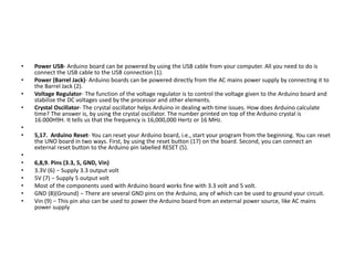
  • 6. • Power USB- Arduino board can be powered by using the USB cable from your computer. All you need to do is connect the USB cable to the USB connection (1). • Power (Barrel Jack)- Arduino boards can be powered directly from the AC mains power supply by connecting it to the Barrel Jack (2). • Voltage Regulator- The function of the voltage regulator is to control the voltage given to the Arduino board and stabilize the DC voltages used by the processor and other elements. • Crystal Oscillator- The crystal oscillator helps Arduino in dealing with time issues. How does Arduino calculate time? The answer is, by using the crystal oscillator. The number printed on top of the Arduino crystal is 16.000H9H. It tells us that the frequency is 16,000,000 Hertz or 16 MHz. • • 5,17. Arduino Reset- You can reset your Arduino board, i.e., start your program from the beginning. You can reset the UNO board in two ways. First, by using the reset button (17) on the board. Second, you can connect an external reset button to the Arduino pin labelled RESET (5). • • 6,8,9. Pins (3.3, 5, GND, Vin) • 3.3V (6) − Supply 3.3 output volt • 5V (7) − Supply 5 output volt • Most of the components used with Arduino board works fine with 3.3 volt and 5 volt. • GND (8)(Ground) − There are several GND pins on the Arduino, any of which can be used to ground your circuit. • Vin (9) − This pin also can be used to power the Arduino board from an external power source, like AC mains power supply
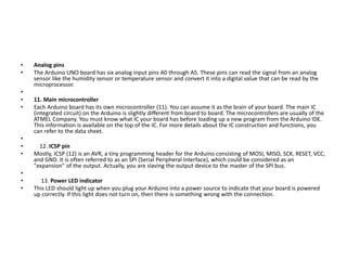
  • 7. • Analog pins • The Arduino UNO board has six analog input pins A0 through A5. These pins can read the signal from an analog sensor like the humidity sensor or temperature sensor and convert it into a digital value that can be read by the microprocessor. • • 11. Main microcontroller • Each Arduino board has its own microcontroller (11). You can assume it as the brain of your board. The main IC (integrated circuit) on the Arduino is slightly different from board to board. The microcontrollers are usually of the ATMEL Company. You must know what IC your board has before loading up a new program from the Arduino IDE. This information is available on the top of the IC. For more details about the IC construction and functions, you can refer to the data sheet. • • 12. ICSP pin • Mostly, ICSP (12) is an AVR, a tiny programming header for the Arduino consisting of MOSI, MISO, SCK, RESET, VCC, and GND. It is often referred to as an SPI (Serial Peripheral Interface), which could be considered as an "expansion" of the output. Actually, you are slaving the output device to the master of the SPI bus. • • 13. Power LED indicator • This LED should light up when you plug your Arduino into a power source to indicate that your board is powered up correctly. If this light does not turn on, then there is something wrong with the connection.
  • 8. • TX and RX LEDs • On your board, you will find two labels: TX (transmit) and RX (receive). They appear in two places on the Arduino UNO board. First, at the digital pins 0 and 1, to indicate the pins responsible for serial communication. Second, the TX and RX led (13). The TX led flashes with different speed while sending the serial data. The speed of flashing depends on the baud rate used by the board. RX flashes during the receiving process. • • 15. Digital I/O • The Arduino UNO board has 14 digital I/O pins (15) (of which 6 provide PWM (Pulse Width Modulation) output. These pins can be configured to work as input digital pins to read logic values (0 or 1) or as digital output pins to drive different modules like LEDs, relays, etc. The pins labeled “~” can be used to generate PWM. • 16. AREF • AREF stands for Analog Reference. It is sometimes, used to set an external reference voltage (between 0 and 5 Volts) as the upper limit for the analog input pins.
  • 9. • Board Details: • Microcontroller: Arduino boards are typically equipped with microcontrollers from the Atmel AVR or ARM families. The most common microcontroller used in Arduino boards is the Atmega series, such as Atmega328P (used in Arduino Uno) or Atmega2560 (used in Arduino Mega). • Digital and Analog I/O Pins: Arduino boards feature a set of digital input/output (I/O) pins and analog input pins. These pins can be used to connect sensors, actuators, and other electronic components to the board. • Power Supply: Arduino boards can be powered via USB connection, an external power supply, or a battery. They usually accept a wide range of input voltages, typically 5V or 3.3V. • Clock Speed: Arduino boards operate at various clock speeds, depending on the specific microcontroller used. Common clock speeds range from 8 MHz to 16 MHz. • Memory: Arduino boards have flash memory for storing the uploaded code (program), as well as SRAM and EEPROM for data storage during program execution. • Interfaces: Arduino boards may include various interfaces such as USB, UART (serial), SPI, I2C, and GPIO pins, allowing communication with other devices and peripherals.
  • 10. • Arduino IDE: • The Arduino Integrated Development Environment (IDE) is a cross-platform application written in Java that provides a simple and intuitive interface for writing, compiling, and uploading code to Arduino boards. •
  • 13. • Menu Bar: Gives you access to the tools needed for creating and saving Arduino sketches. • Verify Button: Compiles your code and checks for errors in spelling or syntax. • Upload Button: Sends the code to the board that’s connected such as Arduino Uno in this case. Lights on the board will blink rapidly when uploading. • New Sketch: Opens a new window containing a blank sketch. • Sketch Name: When the sketch is saved, the name of the sketch is displayed here. • Open Existing Sketch: Allows you to open a saved sketch or one from the stored examples. • Save Sketch: This saves the sketch you currently have open. • Serial Monitor: When the board is connected, this will display the serial information of your Arduino • Code Area: This area is where you compose the code of the sketch that tells the board what to do. • Message Area: This area tells you the status on saving, code compiling, errors and more. • Text Console: Shows the details of an error messages, size of the program that was compiled and additional info. • Board and Serial Port: Tells you what board is being used and what serial port it’s connected to. • Here's an overview of its features: • Code Editor: A text editor with syntax highlighting and auto-indentation for writing Arduino sketches (programs). • Sketches: Arduino programs are called sketches, written in C or C++ programming languages. • Library Manager: A built-in library manager allows users to easily install, manage, and include libraries for interfacing with various sensors, actuators, and communication modules. • Serial Monitor: A tool for debugging Arduino sketches by displaying messages sent from the Arduino board via the Serial communication interface. • Board Manager: Allows users to install and manage different board definitions for various Arduino-compatible boards. • Upload Button: A button to compile and upload the sketch to the connected Arduino board. • Examples: Provides a collection of example sketches demonstrating different functionalities of Arduino boards and peripherals.
  • 14. • Tools: Options for selecting the Arduino board, processor, port, and programmer settings. • Programming with Arduino IDE: • The Arduino Integrated Development Environment (IDE) is the software used to write, compile, and upload code to Arduino boards. Here's a basic overview of the programming process: • Install Arduino IDE: Download and install the Arduino IDE from the official Arduino website (https://www.arduino.cc/en/software). • Connect Arduino Board: Connect your Arduino board to your computer using a USB cable. • Open Arduino IDE: Launch the Arduino IDE software. • Write Code: Write your Arduino code in the IDE. The code consists of two main functions: setup() (executed once at the beginning) and loop() (executed repeatedly). • Verify/Compile Code: Click the "Verify" button (checkmark icon) to compile your code. This checks for syntax errors and compiles the code into machine-readable instructions. • Upload Code: Once the code compiles successfully, click the "Upload" button (right arrow icon) to upload the code to the connected Arduino board. • Monitor Serial Output (Optional): You can use the Serial Monitor feature in the Arduino IDE to debug your code and view output messages from the Arduino board