SlideShare a Scribd company logo
INTERRUPTS IN 8051
• Interrupts are an important feature of a microcontroller, which enables the
microcontroller to respond to external events and requests, which enhances
the multitasking abilities of the microcontroller.
• An interrupt is an external or internal event/command that interrupts the
normal processing of an event and informs the microcontroller that a device
needs its service. Whenever a device needs its service, it sends an interrupt
signal to the microcontroller to send a notification.
• Upon receiving the interrupt signal, the microcontroller stops its existing
program and serves the external device request.
• The program associated with the interrupt is called Interrupt Service
Routine (IRS) or Interrupt handler.
The 8051 features two main types of interrupts,
Hardware Interrupts and Software Interrupts.
The hardware interrupts are triggered by external signals such as peripheral
events or external devices. The microcontroller can be configured to respond to
specific events, allowing for efficient event-driven programming.
Software interrupts are initiated by specific instructions in the program code.
They provide a mechanism for the programmer to force the microcontroller to
interrupt its normal execution and execute a predefined routine.
 The microcontroller automatically maintains its state on interrupt, fetches
the interrupt vector's ISR address, and executes the ISR's operation.
 Once the ISR is finished, the microcontroller restarts the task which has
been interrupted.
Interrupt structure of 8051 Microcontroller
All of the interrupts are disabled by "RESET"; thus, software is required to enable
all of these interrupts.
The relevant interrupt flags are set if any of these five interrupts or all five are
activated. The priority, which is managed by the IP interrupt priority register,
determines which of these interrupts can be set or cleared bit by bit in a specific
function register that is Interrupt Enabled (IE).
Two SFRs control the function of interrupts in 8051 microcontrollers. IE is
responsible for disabling/enabling the function, and IP is responsible for
priority assignment. The priority list offers three levels of interrupt priority:
Reset: When a reset request arrives, everything is stopped, and the
microcontroller restarts. Reset can be used to disable the interrupt priority 1.
Interrupt priority 0 can be disabled by both Reset and interrupt.
Some of the registers used in this microcontroller are :
•IE (Interrupt Enable) Register
•IP (Interrupt Priority) Register
•TCON (Timer Control) Register
Interrupt Handle flowchart
Types of 8051 Microcontroller Interrupts
8051 Microcontroller suffers five different types of interrupts that hampers
the main program execution. These five types of interrupts are:
•Timer 0 overflow interrupt- TF0
•Timer 1 overflow interrupt-TF1
•External hardware interrupt- INT0
•External hardware interrupt- INT1
•Serial communication interrupt- RI/TI
External Hardware Interrupt- (INT0 & INT1)
The 8051 microcontrollers are able to respond to external events through
its external interrupts, INT0 and INT1.
External Interrupt 0 (INT0)
•It is connected to the 8051's pin PORT3.2.
•An interrupt request is issued when this pin transitions
from low to high in response to an external signal.
•It is possible to program the microcontroller to carry out a
particular Interrupt Service Routine (ISR) in response to
this interrupt.
•Set the IE (Interrupt Enable) bit for INT0 in the TCON
register and configure the IT0 (Interrupt Type 0) bit in the
TCON register corresponding to the desired triggering
condition (edge or level-triggered) in order to enable and
configure INT0.
External Interrupt 1 (INT1)
•It is connected to the 8051's pin PORT3.3
•When that particular pin encounters a low-to-
high transitions, INT1, like INT0, creates an
interrupt request.
•By configuring the IT1 (Interrupt Type 1) bit in
the TCON register and setting the IE bit for INT1
in the TCON register, one can enable and
configure INT1.
•A specific ISR can be executed by the
Timer Interrupts (Timer0 and Timer1)
Timer 0 and Timer 1 are hardware timers with
internal timer interrupts featured in the
8051 microcontrollers.
In microcontroller applications, these timers are
used to measure time intervals and generate precise
delays.
The interrupt system of the microcontroller enables
it to react quickly to outside events. Interrupts for
Timer 0 and Timer 1 are produced when their
respective timers exceed their limit.
The microcontroller will run the interrupt service
Timer0 Interrupt
•Since Timer 0 is an 8-bit timer, its count range is 0 to 255.
•There are two modes of operation for it, 13-bit and 16-bit. It employs the TH0
(Timer 0 High) and TL0 (Timer 0 Low) registers in 13-bit mode and only the TH0
register in 16-bit mode.
•It is possible to set timer 0 to interrupt when it approaches zero instead of
staying at its maximum value. The microcontroller can perform a particular
interrupt service routine (ISR) in response to the interrupt request that this
overflow generates.
Timer1 Interrupt
•Timer 1 is a 16-bit timer with a counting range of 0 to 65,535.
•It can operate in 16- or 8-bit mode. It employs the TL1 (Timer 1 Low) and TH1
(Timer 1 High) registers in 8-bit mode and only the TH1 register in 16-bit mode.
•Timer 1 can be set up to produce an interrupt when it overflows, just like
Serial Communication Interrupts (UART)
UART (Universal Asynchronous Receiver/Transmitter) is a serial
communication protocol used with 8051 microcontrollers. Data is sent over a
single cable, bit by bit, in serial transmission. In this sense, "interrupts" refers
to the processes that enable the microcontroller to react quickly to external
events.
Addressing UART communication with the 8051's interrupts:
•Initialization of UART- Set the data format, baud rate, and enable the UART
module by configuring the UART registers.
•Interrupt Enable- Depending on the operation you wish to interrupt for,
enable the UART's transmit interrupt (TI) or receive interrupt (RI).
•ISR (interrupt service routine)- To handle the interrupt, write an ISR. The ISR
in UART communication normally verifies whether the transmit buffer is
ready (TI) or whether data has been received (RI).
•Clearing the Flag- To recognize the interrupt and get ready for the next one,
Interrupt Vector Table
The addresses of different interrupt service routines (ISRs) are
stored in a table called the Interrupt Vector Table (IVT) in an 8051
microcontroller. It is a vital aspect of the interrupt handling
mechanism in the microcontroller.
Every interrupt has a specific place in the IVT, and the addresses
kept there point to the program memory's associated ISR's start.
By guiding the program flow to the proper place, the IVT enables
the microcontroller to respond to external events like hardware
interrupts or external signals quickly and effectively.
Interrupt in 8051 microcontrollers .pptx

More Related Content

PPTX
Interrupts of 8051 microcontroller.newpp
amalajenni
 
PPTX
Embedded systems, lesson 16
REKHASENCHAgs0801bm1
 
PPTX
Interrupts in 8051
Sudhanshu Janwadkar
 
PPTX
Interrupts programming in embedded C using 8051
Vikas Dongre
 
PPTX
Interrupt programming
vijaydeepakg
 
PPT
8051 interrupts
Shreyans Pathak
 
PPT
DPA
Ramasubbu .P
 
PDF
Unit 5_interrupt programming_Part 1
KanchanPatil34
 
Interrupts of 8051 microcontroller.newpp
amalajenni
 
Embedded systems, lesson 16
REKHASENCHAgs0801bm1
 
Interrupts in 8051
Sudhanshu Janwadkar
 
Interrupts programming in embedded C using 8051
Vikas Dongre
 
Interrupt programming
vijaydeepakg
 
8051 interrupts
Shreyans Pathak
 
Unit 5_interrupt programming_Part 1
KanchanPatil34
 

Similar to Interrupt in 8051 microcontrollers .pptx (20)

PPTX
Tin hieu va he thong ádkjfkasjdfkasdfjk_Interrupt.pptx
Lưu Văn Viết
 
PDF
interrupts of 8051.pdf
Srikrishna Thota
 
PPT
Interrupt programming with 8051 microcontroller
Ankit Bhatnagar
 
PPTX
37471656 interrupts
tt_aljobory
 
PPTX
Micro controller 8051 Interrupts
dharmesh nakum
 
PPTX
Interrupt in 8051
ssuser3a47cb
 
PPTX
8051 Microcontroller Overview by Venkatrao Ramisetti
VenkatraoRamisetti
 
PDF
8051 Interrupts
SaravananVijayakumar4
 
PPTX
Types on interrupts in 8051 controller.pptx
EngrShehzadHaneef1
 
PDF
Interrupt
anishgoel
 
PDF
Interrupt
anishgoel
 
PDF
Interrupts of microcontroller 8051
Nilesh Bhaskarrao Bahadure
 
PPTX
interrupts programming in 8051 microcontroller
veenagugri1
 
PPTX
Mc module5 ppt_msj
mangala jolad
 
PDF
Unit 5_Interrupt programming in 8051 micro controller - part 2
KanchanPatil34
 
PPTX
MPMC UNIT 2 MPMC UNIT 2 MPMC UNIT 2 MPMC UNIT 2
AnbazhaganSelvanatha
 
PPTX
MPMC UNIT 2 MPMC UNIT 2 MPMC UNIT 2 MPMC UNIT 2
AnbazhaganSelvanatha
 
PPSX
Microprocessor Architecture 4
Dr.YNM
 
PDF
Microprocessor 8051
Anil Maurya
 
Tin hieu va he thong ádkjfkasjdfkasdfjk_Interrupt.pptx
Lưu Văn Viết
 
interrupts of 8051.pdf
Srikrishna Thota
 
Interrupt programming with 8051 microcontroller
Ankit Bhatnagar
 
37471656 interrupts
tt_aljobory
 
Micro controller 8051 Interrupts
dharmesh nakum
 
Interrupt in 8051
ssuser3a47cb
 
8051 Microcontroller Overview by Venkatrao Ramisetti
VenkatraoRamisetti
 
8051 Interrupts
SaravananVijayakumar4
 
Types on interrupts in 8051 controller.pptx
EngrShehzadHaneef1
 
Interrupt
anishgoel
 
Interrupt
anishgoel
 
Interrupts of microcontroller 8051
Nilesh Bhaskarrao Bahadure
 
interrupts programming in 8051 microcontroller
veenagugri1
 
Mc module5 ppt_msj
mangala jolad
 
Unit 5_Interrupt programming in 8051 micro controller - part 2
KanchanPatil34
 
MPMC UNIT 2 MPMC UNIT 2 MPMC UNIT 2 MPMC UNIT 2
AnbazhaganSelvanatha
 
MPMC UNIT 2 MPMC UNIT 2 MPMC UNIT 2 MPMC UNIT 2
AnbazhaganSelvanatha
 
Microprocessor Architecture 4
Dr.YNM
 
Microprocessor 8051
Anil Maurya
 
Ad

More from neethujaaps (7)

PPT
29317254-Standard-Single-Purpose-Processors-Peripherals.ppt
neethujaaps
 
PDF
Advanced Microprocessors Class Notes.pdf
neethujaaps
 
PPTX
8086 Microprocessor Interrupts - UG Final Sem.pptx
neethujaaps
 
PPTX
De-Multiplexing of Address and Data Bus in 8086.pptx
neethujaaps
 
PPTX
Graphene Transistors By Alex Van Eck.pptx
neethujaaps
 
PPT
8086 Architecture & pipelining presentation.ppt
neethujaaps
 
PPTX
ELE641A-powe Electronics power point presentation.pptx
neethujaaps
 
29317254-Standard-Single-Purpose-Processors-Peripherals.ppt
neethujaaps
 
Advanced Microprocessors Class Notes.pdf
neethujaaps
 
8086 Microprocessor Interrupts - UG Final Sem.pptx
neethujaaps
 
De-Multiplexing of Address and Data Bus in 8086.pptx
neethujaaps
 
Graphene Transistors By Alex Van Eck.pptx
neethujaaps
 
8086 Architecture & pipelining presentation.ppt
neethujaaps
 
ELE641A-powe Electronics power point presentation.pptx
neethujaaps
 
Ad

Recently uploaded (20)

PPTX
CDH. pptx
AneetaSharma15
 
PDF
Antianginal agents, Definition, Classification, MOA.pdf
Prerana Jadhav
 
PPTX
Python-Application-in-Drug-Design by R D Jawarkar.pptx
Rahul Jawarkar
 
PDF
Biological Classification Class 11th NCERT CBSE NEET.pdf
NehaRohtagi1
 
PPTX
Virus sequence retrieval from NCBI database
yamunaK13
 
PDF
Virat Kohli- the Pride of Indian cricket
kushpar147
 
PPTX
A Smarter Way to Think About Choosing a College
Cyndy McDonald
 
PDF
Review of Related Literature & Studies.pdf
Thelma Villaflores
 
PPTX
Command Palatte in Odoo 18.1 Spreadsheet - Odoo Slides
Celine George
 
PDF
The-Invisible-Living-World-Beyond-Our-Naked-Eye chapter 2.pdf/8th science cur...
Sandeep Swamy
 
PDF
The Minister of Tourism, Culture and Creative Arts, Abla Dzifa Gomashie has e...
nservice241
 
DOCX
SAROCES Action-Plan FOR ARAL PROGRAM IN DEPED
Levenmartlacuna1
 
PPTX
Tips Management in Odoo 18 POS - Odoo Slides
Celine George
 
PPTX
Dakar Framework Education For All- 2000(Act)
santoshmohalik1
 
DOCX
Unit 5: Speech-language and swallowing disorders
JELLA VISHNU DURGA PRASAD
 
PDF
Health-The-Ultimate-Treasure (1).pdf/8th class science curiosity /samyans edu...
Sandeep Swamy
 
PPTX
Artificial Intelligence in Gastroentrology: Advancements and Future Presprec...
AyanHossain
 
PPTX
Artificial-Intelligence-in-Drug-Discovery by R D Jawarkar.pptx
Rahul Jawarkar
 
PPTX
Kanban Cards _ Mass Action in Odoo 18.2 - Odoo Slides
Celine George
 
PPTX
Basics and rules of probability with real-life uses
ravatkaran694
 
CDH. pptx
AneetaSharma15
 
Antianginal agents, Definition, Classification, MOA.pdf
Prerana Jadhav
 
Python-Application-in-Drug-Design by R D Jawarkar.pptx
Rahul Jawarkar
 
Biological Classification Class 11th NCERT CBSE NEET.pdf
NehaRohtagi1
 
Virus sequence retrieval from NCBI database
yamunaK13
 
Virat Kohli- the Pride of Indian cricket
kushpar147
 
A Smarter Way to Think About Choosing a College
Cyndy McDonald
 
Review of Related Literature & Studies.pdf
Thelma Villaflores
 
Command Palatte in Odoo 18.1 Spreadsheet - Odoo Slides
Celine George
 
The-Invisible-Living-World-Beyond-Our-Naked-Eye chapter 2.pdf/8th science cur...
Sandeep Swamy
 
The Minister of Tourism, Culture and Creative Arts, Abla Dzifa Gomashie has e...
nservice241
 
SAROCES Action-Plan FOR ARAL PROGRAM IN DEPED
Levenmartlacuna1
 
Tips Management in Odoo 18 POS - Odoo Slides
Celine George
 
Dakar Framework Education For All- 2000(Act)
santoshmohalik1
 
Unit 5: Speech-language and swallowing disorders
JELLA VISHNU DURGA PRASAD
 
Health-The-Ultimate-Treasure (1).pdf/8th class science curiosity /samyans edu...
Sandeep Swamy
 
Artificial Intelligence in Gastroentrology: Advancements and Future Presprec...
AyanHossain
 
Artificial-Intelligence-in-Drug-Discovery by R D Jawarkar.pptx
Rahul Jawarkar
 
Kanban Cards _ Mass Action in Odoo 18.2 - Odoo Slides
Celine George
 
Basics and rules of probability with real-life uses
ravatkaran694
 

Interrupt in 8051 microcontrollers .pptx

  • 1. INTERRUPTS IN 8051 • Interrupts are an important feature of a microcontroller, which enables the microcontroller to respond to external events and requests, which enhances the multitasking abilities of the microcontroller. • An interrupt is an external or internal event/command that interrupts the normal processing of an event and informs the microcontroller that a device needs its service. Whenever a device needs its service, it sends an interrupt signal to the microcontroller to send a notification. • Upon receiving the interrupt signal, the microcontroller stops its existing program and serves the external device request. • The program associated with the interrupt is called Interrupt Service Routine (IRS) or Interrupt handler.
  • 2. The 8051 features two main types of interrupts, Hardware Interrupts and Software Interrupts. The hardware interrupts are triggered by external signals such as peripheral events or external devices. The microcontroller can be configured to respond to specific events, allowing for efficient event-driven programming. Software interrupts are initiated by specific instructions in the program code. They provide a mechanism for the programmer to force the microcontroller to interrupt its normal execution and execute a predefined routine.  The microcontroller automatically maintains its state on interrupt, fetches the interrupt vector's ISR address, and executes the ISR's operation.  Once the ISR is finished, the microcontroller restarts the task which has been interrupted.
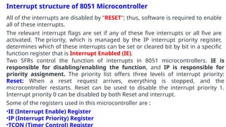
  • 3. Interrupt structure of 8051 Microcontroller All of the interrupts are disabled by "RESET"; thus, software is required to enable all of these interrupts. The relevant interrupt flags are set if any of these five interrupts or all five are activated. The priority, which is managed by the IP interrupt priority register, determines which of these interrupts can be set or cleared bit by bit in a specific function register that is Interrupt Enabled (IE). Two SFRs control the function of interrupts in 8051 microcontrollers. IE is responsible for disabling/enabling the function, and IP is responsible for priority assignment. The priority list offers three levels of interrupt priority: Reset: When a reset request arrives, everything is stopped, and the microcontroller restarts. Reset can be used to disable the interrupt priority 1. Interrupt priority 0 can be disabled by both Reset and interrupt. Some of the registers used in this microcontroller are : •IE (Interrupt Enable) Register •IP (Interrupt Priority) Register •TCON (Timer Control) Register
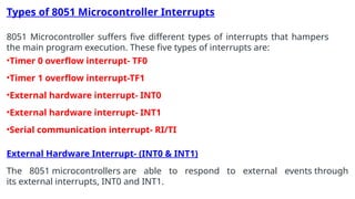
  • 5. Types of 8051 Microcontroller Interrupts 8051 Microcontroller suffers five different types of interrupts that hampers the main program execution. These five types of interrupts are: •Timer 0 overflow interrupt- TF0 •Timer 1 overflow interrupt-TF1 •External hardware interrupt- INT0 •External hardware interrupt- INT1 •Serial communication interrupt- RI/TI External Hardware Interrupt- (INT0 & INT1) The 8051 microcontrollers are able to respond to external events through its external interrupts, INT0 and INT1.
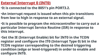
  • 6. External Interrupt 0 (INT0) •It is connected to the 8051's pin PORT3.2. •An interrupt request is issued when this pin transitions from low to high in response to an external signal. •It is possible to program the microcontroller to carry out a particular Interrupt Service Routine (ISR) in response to this interrupt. •Set the IE (Interrupt Enable) bit for INT0 in the TCON register and configure the IT0 (Interrupt Type 0) bit in the TCON register corresponding to the desired triggering condition (edge or level-triggered) in order to enable and configure INT0.
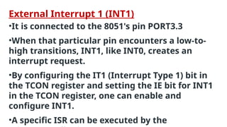
  • 7. External Interrupt 1 (INT1) •It is connected to the 8051's pin PORT3.3 •When that particular pin encounters a low-to- high transitions, INT1, like INT0, creates an interrupt request. •By configuring the IT1 (Interrupt Type 1) bit in the TCON register and setting the IE bit for INT1 in the TCON register, one can enable and configure INT1. •A specific ISR can be executed by the
  • 8. Timer Interrupts (Timer0 and Timer1) Timer 0 and Timer 1 are hardware timers with internal timer interrupts featured in the 8051 microcontrollers. In microcontroller applications, these timers are used to measure time intervals and generate precise delays. The interrupt system of the microcontroller enables it to react quickly to outside events. Interrupts for Timer 0 and Timer 1 are produced when their respective timers exceed their limit. The microcontroller will run the interrupt service
  • 9. Timer0 Interrupt •Since Timer 0 is an 8-bit timer, its count range is 0 to 255. •There are two modes of operation for it, 13-bit and 16-bit. It employs the TH0 (Timer 0 High) and TL0 (Timer 0 Low) registers in 13-bit mode and only the TH0 register in 16-bit mode. •It is possible to set timer 0 to interrupt when it approaches zero instead of staying at its maximum value. The microcontroller can perform a particular interrupt service routine (ISR) in response to the interrupt request that this overflow generates. Timer1 Interrupt •Timer 1 is a 16-bit timer with a counting range of 0 to 65,535. •It can operate in 16- or 8-bit mode. It employs the TL1 (Timer 1 Low) and TH1 (Timer 1 High) registers in 8-bit mode and only the TH1 register in 16-bit mode. •Timer 1 can be set up to produce an interrupt when it overflows, just like
  • 10. Serial Communication Interrupts (UART) UART (Universal Asynchronous Receiver/Transmitter) is a serial communication protocol used with 8051 microcontrollers. Data is sent over a single cable, bit by bit, in serial transmission. In this sense, "interrupts" refers to the processes that enable the microcontroller to react quickly to external events. Addressing UART communication with the 8051's interrupts: •Initialization of UART- Set the data format, baud rate, and enable the UART module by configuring the UART registers. •Interrupt Enable- Depending on the operation you wish to interrupt for, enable the UART's transmit interrupt (TI) or receive interrupt (RI). •ISR (interrupt service routine)- To handle the interrupt, write an ISR. The ISR in UART communication normally verifies whether the transmit buffer is ready (TI) or whether data has been received (RI). •Clearing the Flag- To recognize the interrupt and get ready for the next one,
  • 11. Interrupt Vector Table The addresses of different interrupt service routines (ISRs) are stored in a table called the Interrupt Vector Table (IVT) in an 8051 microcontroller. It is a vital aspect of the interrupt handling mechanism in the microcontroller. Every interrupt has a specific place in the IVT, and the addresses kept there point to the program memory's associated ISR's start. By guiding the program flow to the proper place, the IVT enables the microcontroller to respond to external events like hardware interrupts or external signals quickly and effectively.