SlideShare a Scribd company logo
Introduction to ARM
processor
T.Ramprakash
AP/ECE
Ramco Institute of Technology
1
Flow of Topics
• ARM Architecture
• ARM programmer’s model
• ARM Development tools
• Memory Hierarchy
• ARM Assembly Language Programming
• Simple Examples
• Architectural Support for Operating systems
2
Why ARM
3
Why ARM
• The company has publicly announced 64-bit
architectural licensees:
• Applied Micro,
• Broadcom,
• Cavium,
• Apple,
• Huawei,
• Nvidia,
• AMD and
• Samsung.
4
Why ARM
• It also has another seven publicly announced
32-bit architectural licensees, of which five –
• Marvell,
• Microsoft,
• Qualcomm,
• Intel and
• Faraday
5
Why ARM
• ARM  Advanced RISC Machine
• Low power, Low cost, Tiny
• 8/16/32/64 bit processor
• Thumb mode
• TDMI  Thumb mode Debug interface Multiplier ICE interface
• ARM is one of the most licensed and thus
widespread processor cores in the world
• Used especially in portable devices due to low
power consumption and reasonable
performance 6
ARM Architecture
• Follows RISC Architecture
• Both in Von Neumann and Harvard Architecture
• Both Little endian and Big endian
• 32 bit processor
• 32 bit address line
7
ARM Architecture
• Features Used from RISC design
– A Load/Store Architecture
– Fixed length 32 bit instruction
– 3 address instruction formats
• Features rejected from RISC design
– Register windows
– Delayed branches
– Single cycle execution of all instructions 8
Programming Model
9
Programming Model
• ARM’s Register
• CPSR Register
• Memory System
• Load Store Architecture
• ARM Instruction Set
• I/O system
• ARM exceptions
10
ARM Registers
• When writing user-level programs, only
the 15 general purpose 32bit registers
(r0 to r14), the program counter (r15)
and the current program status register
(CPSR) need be considered
• The remaining registers are used only
for system level programming and for
handling exceptions
11
Current Program Status Registers
• Condition code flags
– N = Negative result from ALU
– Z = Zero result from ALU
– C = ALU operation Carried out
– V = ALU operation oVerflowed
• Mode bits
– Specify the processor mode
• Interrupt Disable bits.
– I = 1: Disables the IRQ.
– F = 1: Disables the FIQ.
• T Bit
– Architecture xT only
– T = 0: Processor in ARM state
– T = 1: Processor in Thumb state
12
Current Program Status Registers
13
Operating Modes
• The ARM7TDMI processor has seven modes of operations:
– User mode(usr)
• Normal program execution mode
– Fast Interrupt mode(fiq)
• Supports a high-speed data transfer or channel process.
– Interrupt mode(irq)
• Used for general-purpose interrupt handling.
– Supervisor mode(svc)
• Protected mode for the operating system.
– Abort mode(abt)
• implements virtual memory and/or memory protection
– System mode(sys)
• A privileged user mode for the operating system. (runs OS
tasks)
– Undefined mode(und)
• supports a software emulation of hardware coprocessors
• Except user mode, all are known as privileged mode. 14
Register Organization Summary
User
mode
r0-r7,
r15,
and
cpsr
r8
r9
r10
r11
r12
r13 (sp)
r14 (lr)
spsr
FIQ
r8
r9
r10
r11
r12
r13 (sp)
r14 (lr)
r15 (pc)
cpsr
r0
r1
r2
r3
r4
r5
r6
r7
User
r13 (sp)
r14 (lr)
spsr
IRQ
User
mode
r0-r12,
r15,
and
cpsr
r13 (sp)
r14 (lr)
spsr
Undef
User
mode
r0-r12,
r15,
and
cpsr
r13 (sp)
r14 (lr)
spsr
SVC
User
mode
r0-r12,
r15,
and
cpsr
r13 (sp)
r14 (lr)
spsr
Abort
User
mode
r0-r12,
r15,
and
cpsr
Thumb state
Low registers
Thumb state
High registers
Note: System mode uses the User mode register set
15
Memory System
• In addition to the processor register, ARM
system has memory state
• Memory may be viewed as a linear array of
bytes numbered form 0 up to 232 – 1
• Data items may be 8 bit bytes, 16 bit half
words or 32 bit words
• Words are always aligned on 4 byte
boundaries
• Half words are aligned on even byte
boundaries
16
Memory System
• Byte may occupy any of these locations
• Half-words occupy two byte locations starting at an
even byte address.
• A word-sized data item must occupy a group of four
byte locations starting at a byte address which is a
multiple of four
17
Load Store Architecture
• ARM employs a load-store architecture
• This means that the instruction set will only
process values which are in registers, and will
always place the results of such processing
into a register.
• The only operations which apply to memory
state are ones which copy memory values into
registers (load instructions) or copy register
values into memory (store instructions).
18
Load Store Architecture
• ARM does not support such 'memory-to-memory' operations.
• Therefore all ARM instructions fall into one of the following
three categories:
• Data processing instructions.
– These use and change only register values. For example, an
instruction can add two registers and place the result in a register.
• Data transfer instructions.
– These copy memory values into registers (load instructions) or
copy register values into memory (store instructions).
• Control flow instructions.
– Control flow instructions cause execution to switch to a different
address, either permanently (branch instructions) or saving a
return address to resume the original sequence (branch and link
instructions) or trapping into system code (supervisor calls).
19
Supervisor Mode
• The ARM processor supports a protected supervisor
mode.
• The protection mechanism ensures that user code
cannot gain supervisor privileges without appropriate
checks being carried out to ensure that the code is not
attempting illegal operations.
• The upshot of this for the user-level programmer is
that system-level functions can only be accessed
through specified supervisor calls.
• These functions generally include any accesses to
hardware peripheral registers, and to widely used
operations such as character input and output.
• Supervisor (svc) mode: A privileged mode entered
when an SVC instruction is executed. 20
Arm Instruction Set
• The most notable features of the ARM instruction set are:
– 32 bits wide
– The load-store architecture;
– 3-address data processing instructions
– conditional execution of every instruction;
– The inclusion of very powerful load and store multiple register
instructions;
– The ability to perform a general shift operation and a general ALU
operation in a single instruction that executes in a single clock
cycle
– Open instruction set extension through the coprocessor
instruction set, including adding new registers and data types to
the programmer's model
– A very dense 16-bit compressed representation of the instruction
set in the Thumb architecture. 21
I/O System
• The ARM handles I/O (input/output) peripherals
(such as disk controllers, network interfaces, and so
on) as memory-mapped devices with interrupt
support.
• The internal registers in these devices appear as
addressable locations within the ARM's memory
map and may be read and written using the same
(load-store) instructions as any other memory
locations.
22
ARM Exceptions
• The ARM architecture supports a range of
interrupts, traps and supervisor calls, all grouped
under the general heading of exceptions.
• The general way of handling all these exceptions are
– The current state is saved by copying the PC into rl4_exc
and the CPSR into SPSR_exc
– The processor operating mode is changed to the
appropriate exception mode.
– The PC is forced to a value between 0016 and 1C16, the
particular value depending on the type of exception.
23
ARM Development Tools
24
ARM Development Tools
25
ARM Development Tools
26
ARM C Compiler
• The ARM C compiler is compliant with the ANSI
(American National Standards Institute)
standard for C and is supported by the
appropriate library of standard functions.
• It uses the ARM Procedure Call Standard for all
externally available functions.
• It can be told to produce assembly source
output instead of ARM object format
• The compiler can also produce Thumb code.
27
ARM Assembler
• The ARM assembler is a full macro assembler
which produces ARM object format output that
can be linked with output from the C compiler.
28
Linker
• The linker takes one or more object files and
combines them into an executable program.
• It resolves symbolic references between the
object files and extracts object modules from
libraries as needed by the program.
• It can assemble the various components of the
program in a number of different ways,
depending on whether the code is to run in
RAM (Random Access Memory, which can be
read and written) or ROM (Read Only Memory),
whether overlays are required, and so on 29
ARMsd
• The ARM symbolic debugger is a front-end
interface to assist in debugging programs running
either under emulation (on the ARMulator) or
remotely on a target system such as the ARM
development board
• ARMsd allows an executable program to be loaded
into the ARMulator or a development board and
run.
• It allows the setting of breakpoints, which are
addresses in the code that, if executed, cause
execution to halt so that the processor state can be
examined
30
ARMulator
• The ARMulator (ARM emulator) is a suite of
programs that models the behaviour of various
ARM processor cores in software on a host system.
• It can operate at various levels of accuracy:
– Instruction-accurate modelling gives the exact
behaviour of the system state without regard to the
precise timing characteristics of the processor.
– Cycle-accurate modelling gives the exact behaviour of
the processor on a cycleby-cycle basis, allowing the
exact number of clock cycles that a program requires to
be established.
– Timing-accurate modelling presents signals at the
correct time within a cycle, allowing logic delays to be
accounted for. 31
ARM development board
32
ARM development board
• The ARM Development Board is a circuit board
incorporating a range of components and interfaces to
support the development of ARM-based systems.
• It includes an ARM core (for example, an ARM7TDMI),
memory components which can be configured to
match the performance and bus- width of the memory
in the target system, and electrically programmable
devices which can be configured to emulate
application-specific peripherals.
• It can support both hardware and software
development before the final application-specific
hardware is available. 33
Memory Hierarchy
34
Memory Hierarchy
• A typical system has several different memory
subsystems.
35
Memory Hierarchy
• Processor registers
– are managed directly by the compiler
• Cache
– is managed automatically by the hardware
• On-chip RAM
– is managed by the programmer
• Off-chip Memory
– is managed by the operating system
36
Memory Hierarchy
• Processor registers:
– It is viewed as the top of the memory hierarchy
– 32 – 32bits register
– Access time of few Nano seconds
• On-chip cache or RAM:
– 8 to 32 Kbytes
– Access time around ten nanoseconds.
• second-level off-chip cache
– few hundred Kbytes
– Access time of a few tens of nanoseconds
• Main memory
– tens of megabytes of dynamic RAM
– Access time around 100 nanoseconds.
• Backup store
– usually on a hard disk,
– Capacity will be hundreds of Mbytes up to a few Gbytes
– Access time of a few tens of milliseconds 37
Memory Hierarchy
• The main objective is to approach:
– The performance of the fastest memory at the cost/bit
of the slowest memory
38
On-chip RAM
• System benefits of on-chip memory:
– increased performance
– no wait states
– reduced power consumption
– improved EMC
• On-chip RAM (“Tightly Coupled Memory”) is used
in preference to a cache in some embedded
systems:
– it is simpler, cheaper and uses less power
– its behaviour is more deterministic
– however it requires explicit management 39
Caches
• A cache is a small on-chip memory which
automatically:
– keeps copies of recently used memory values
– supplies these to the processor when it asks for them
again thereby avoiding an off-chip memory access
– Decides which values to over-write when it is full
40
Caches - Classification
• Based up on the storage of Instruction and data,
caches can be classified into
– Unified Cache
– Modified Harvard
41
Unified Cache
• This is a single cache for both instructions and data
42
Modified Harvard
• Separate cache for both instructions and data
43
Memory Hierarchy
• An access to an item which is in the cache is called
a hit
• An access to an item which is not in the cache is a
miss.
• The proportion of all the memory accesses that are
satisfied by the cache is the hit rate, usually
expressed as a percentage, and the proportion that
are not is the miss rate.
44
Direct mapped Cache
Writing is more complicated than reading
Write-through
Write-back 45
Direct mapped Cache
46
Two way set associative Cache
47
Two way set associative Cache
• two (smaller) cache blocks
• two chances to store any line
• better hit rate
• more expensive
• can extend to 4-way, etc.
48
Fully associative Cache
49
Fully associative Cache
• More places to store given line
• Even better hit rate
• Even more expensive
• (Potentially) slower
• Requires CAM (Content Addressable Memory)
50
Comparison
Direct mapped Set associative Fully associative
If each block has only one
place that it can appear in
the cache, it is said to be
direct mapped
If a block can be placed in a
restricted set of places in
the cache, the cache
is said to be set associative
If a block can be placed
anywhere in the cache, the
cache is said to be
fully associative.
simple, cheap, fast compromise slow, expensive
subject to ‘thrashing’ may be 2-, 4-, 8-, etc. way best hit rate
choice for large caches often preferred choice for small caches
51
Comparison
• Write-through
– All write operations are passed to main memory; if the addressed location is
currently held in the cache, the cache is updated to hold the new value. The
processor must slow down to main memory speed while the write takes place.
• Write-through with buffered write
– Here all write operations are still passed to main memory and the cache
updated as appropriate, but instead of slowing the processor down to main
memory speed the write address and data are stored in a write buffer which
can accept the write information at high speed. The write buffer then transfers
the data to main memory, at main memory speed, while the processor
continues with its next task.
• Copy-back (also known as write-back)
– A copy-back cache is not kept coherent with main memory. Write operations
update only the cache, so cache lines must remember when they have been
modified (usually using a dirty bit on each line or block). If a dirty cache line is
allocated to new data it must be copied back to memory before the line is
reused.
52
Memory Management
• There are two principal approaches to
memory management, called
– Segmentation
– Paging
53
Segment
• The simplest form of memory management
allows an application to view its memory as a
set of segments, where each segment
contains a particular sort of information.
• For instance
– Code segment
– Data segment
– Stack segment
54
Segmented memory management
55
Paging
• In a paging memory management scheme
both the logical and the physical address
spaces are divided into fixed-size components
called pages.
• A page is usually a few kilobytes in size, but
different architectures use different page
sizes.
56
Paging
57
ARM Assembly Language Programming
• Data processing Instructions
• Data Transfer Instructions
• Control flow Instruction
58
Data Processing Instructions
• Simple register operands
• Register movement operations
• Comparison operations
• Immediate Operands
• Shifted register operands
• Multiplies
59
Simple Register Operands
60
Simple Register Operands
61
Register movement operations
62
Comparison operations
63
Immediate operands
ADD r3, r3, #1
AND r8, r7, #FF
64
Shifted Register Operands
65
Shifted Register Operands
66
Multiplies
• Immediate second operands are not supported.
• The result register must not be the same as the
first source register.
67
Data Transfer Instructions
• Register indirect addressing mode
• Initializing an address pointer
• Single register load store instruction
• Base plus offset addressing
• Multiple register data transfer
• Block copy addressing
68
Register indirect addressing mode
69
Initializing an address pointer
70
Single register load store instruction
71
Single register load store instruction
72
Base plus offset Addressing
LDR r0, [r1,#4] ; r0= mem32[r1+4]
LDR r0, [r1,#4]! ; r0= mem32[r1+4]
; r1=r1+4
73
Base plus offset Addressing
74
Base plus offset Addressing
75
Multiple register data transfer
76
SWAP Instruction
77
Control Flow Instructions
• Branch Instructions
• Conditional Branches
78
Branch Instructions
79
Conditional Branches
80
Conditional Branches
Z=1
C=1
C=0
N=1
N=0
V=1
V=0
C=1 & Z=0
C=0 & Z=1
N=V
N!=V
Z=0 & N=V
Z=1 & N!=V
Z=0
81
Examples
82
Examples
If ((a==b )&& (c==d))
{
e++;
}
CMP r0, r1
CMPEQ r2, r3
ADDEQ r4, r4, #1
83
Examples
• Write a program to print ‘Helloworld’
84
Examples
• Move content of table 1 to table 2 and print
85
Examples
• Printout r1 in Hexadecimal
86
Examples
• Output text string immediately following the CALL
87
Architectural Support for Operating systems
• ARM system control coprocessor
• CP15 protection unit registers
• CP15 MMU registers
• ARM MMU architecture
• Context switching
• Input/Output
88
ARM system control coprocessor
• ARM system control coprocessor is an on-chip coprocessor,
using coprocessor number 15 (CP15)
• It controls the operation of the
– On chip cache
– Memory management
– Protections unit
– Write buffer
– Prefetch buffer
– Branch target cache
– System configurations signals
89
CP15 Protection Unit registers
90
CP15 Protection Unit registers
• Register 0 (ID Register)
• Bits [3:0]  revision number,
• bits [15:4] 3-digit part number
• bits [23:16] architecture version
(0 for version 3,
1 for version 4,
2 for version 4T,
4 for version 5T)
• bits [31:24] ASCII code of an implementer's
trademark
91
CP15 Protection Unit registers
• Register 1 (Configuration)
• All bits are cleared on reset.
• M  Protection unit,
• C  data or unified cache,
• W  write buffer,
• B switches from little- to big-endian byte ordering,
• I enables the instruction cache when this is separate from the data cache,
• V causes the exception vectors to move to near the top of the address space,
• S, Lck, F and Bnk are used to control the cache (on the ARM740T), and
• nf and iA control various clock mechanisms (on the ARM940T).
92
CP15 Protection Unit registers
• Register 2 (Cache Control)
• It controls the cache ability of the eight individual protection regions
• Bit 0 enables the cache for loads within region 0,
• Bit 1 likewise for region 1, and so on.
• The ARM940T has separate protection units on its instruction and data ports
• Cop2 is used to determine which unit is accessed:
• Cop2 = 0 gives access to the protection unit on the data port;
• Cop2 = 1 gives access to the protection unit on the instruction port
93
CP15 Protection Unit registers
• Register 3 (Write Buffer Control)
• It defines whether or not the write buffer should be used for each of the
protection regions.
• The ARM940T instruction port is read-only,
• The write buffer can only be enabled for the data port
• and so Cop2 should always be zero
94
CP15 Protection Unit registers
• Register 5 (Access Permission)
• 00  No access
• 01  Privileged modes
• 10  Privileged full access and user read only
• 11  Full access.
• Again the ARM940T uses the Cop2 field to
differentiate
 1 instruction protection units
 0  data protection units. 95
CP15 Protection Unit registers
• Register 6 (Region Base and Size)
• It defines the start address and size of each of the
eight regions.
96
CP15 Protection Unit registers
• Register 7 (Cache Operation)
– It controls various cache operations and
– its operation is different for the ARM740T and the
ARM940T.
• Register 9 (Cache Lock Down)
– It is used in the ARM940T to lock down areas of
the cache.
97
CP15 Protection Unit registers
• Register 15 (Test)
– It is used in the ARM940T to modify the cache
allocation algorithm from random to round-robin.
– This is intended for use only during silicon
production testing.
98
CP15 MMU Registers
99
CP15 MMU Registers
• Register 0
• Bits [3:0]  revision number,
• bits [15:4] 3-digit part number
• bits [23:16] architecture version
(0 for version 3,
1 for version 4)
• bits [31:24] ASCII code of an implementer's
trademark
100
CP15 MMU Registers
• Register 1 (Control)
• All bits are cleared on reset.
• M  MMUunit,
• A  Address Alignment fault checking,
• C data or unified cache
• W  write buffer,
• P  switches from 26 to 32 bit address range
• L  switches to late abort timeing
• B switches from little- to big-endian byte ordering,
• S & R  modify the MMU system and ROM protection states
• F  controls the external coprocessor communications
• Z  enables branch prediction
• I  enables the instruction cache when this is separate from the data cache,
• V causes the exception vectors to move to near the top of the address space,
• RR  enables cache replacement algorithm 101
CP15 MMU Registers
• Register 2 (Translation Table Base)
• It contains the address of the start of the
currently active first-level translation table
102
CP15 MMU Registers
• Register 3(Domain Access Control)
103
CP15 MMU Registers
• Register 5 (Fault Status)
• It indicates the type of fault and the domain of
the last data access that aborted.
• D is set on a data breakpoint.
104
CP15 MMU Registers
• Register 6 (Fault Address)
• It contains the address of the last data access
that aborted.
105
CP15 MMU Registers
• Register 7 (Cache Operation)
• It is used to perform a
– Number of cache,
– Write buffer,
– Prefetch buffer and
– Branch target cache clean and/or
– Flush operations.
• The data supplied should be either zero or a
relevant virtual address.
106
CP15 MMU Registers
• Register 8 (TLB Operations)
• It is used to perform a number of
– TLB operations,
– Flushing single entries or the whole TLB and
– Supporting unified or separate instruction and
data TLBs
107
CP15 MMU Registers
• Register 9 (Read Buffer Operation)
– It is used to control the read buffer
• Register 10 (TLB Lockdown)
– It is used to control TLB lockdown functions
• Register 13 (Process ID Mapping)
– It is used to remap virtual addresses through a
process ID register.
108
ARM MMU Architecture
• An MMU performs two primary functions:
– It translates virtual addresses into physical
addresses.
– It controls memory access permissions, aborting
illegal accesses.
109
Memory Granularity
• The units that can be used are:
– Sections.
• These are 1 Mbyte blocks of memory.
– Large pages.
• These are 64 Kbyte blocks of memory, and within a
large page access control is applied to individual 16
Kbyte subpages.
– Small pages.
• These are 4 Kbyte blocks of memory, and within a small
page access control is applied to individual 1 Kbyte
subpages.
– Tiny pages.
• Some of the latest CPUs also support 1 Kbyte 'tiny'
pages. 110
Domains
• Domain is a group of sections or pages which
have particular access permission
• The access control is based on two sorts of
programs
– Clients
• Clients are users of domains and must observe the
access permissions of the individual sections and pages
that make up the domain.
– Managers
• Managers are the controllers of the domain and can
bypass the access permissions of individual sections or
pages
111
Translation Process
• First Translation fetch
• Section Translation
• Page Translation
• Access Permissions
112
First Translation fetch
113
Section Translation
114
Page Translation
115
Access Permission Checking Scheme
116
Access Permission Checking Scheme
117
Context Switching
• When a process switch takes place, the
context of the old process must be saved and
that of the new process restored
118
Context Switching
• A process runs in a context, which is all the
system state that must be established for the
process to run correctly.
• This state includes:
– Processor's registers,
– Program counter,
– Stack pointer, and so on;
– the values in the floating-point registers,
– the translation tables in memory
– Data values used by the process in memory.
119
Memory mapped peripherals
• A peripheral device, such as a serial line
controller, contains a number of registers.
• In a memory-mapped system, each of these
registers appears like a memory location at a
particular address.
• A serial line controller may have a set of registers
as follows:
• A transmit data register (write only);
• A receive data register (read only);
• A control register (read/write);
• RTS (request to send).
• An interrupt enable register (read/write);
• A status register (read only). 120
Memory mapped Issues
• Note that a memory-mapped peripheral register behaves
differently from memory.
• Two consecutive reads to the read data register will
probably deliver different results even though no write to
that location has taken place
• Such locations are termed read-sensitive
• Programs must be written very carefully where read-
sensitive locations are involved, and, in particular, such
locations must not be copied into a cache memory 121
Reference
1. Peatman,J.B., “Design with PIC Micro
Controllers”PearsonEducation,3rdEdition,
2004.
2. Furber,S., “ARM System on Chip Architecture”
Addison Wesley trade Computer
Publication, 2000
122

More Related Content

What's hot (20)

PDF
ARM Architecture
Dwight Sabio
 
PPT
06. thumb instructions
balaji raja rajan Venkatachalam
 
DOCX
ARM7-ARCHITECTURE
Dr.YNM
 
PPTX
LPC 2148 ARM MICROCONTROLLER
sravannunna24
 
PPTX
ARM Processor
Aniket Thakur
 
PDF
ARM architcture
Hossam Adel
 
PPT
EPROM, PROM & ROM
Abhilash Nair
 
PPTX
4.programmable dma controller 8257
MdFazleRabbi18
 
PPT
SPI Bus Protocol
Sudhanshu Janwadkar
 
PPT
FPGA
subin mathew
 
PDF
ARM CORTEX M3 PPT
Gaurav Verma
 
PPT
ARM - Advance RISC Machine
EdutechLearners
 
PPSX
LECT 1: ARM PROCESSORS
Dr.YNM
 
PDF
8086 modes
PDFSHARE
 
PPT
8086 pin details
AJAL A J
 
PPTX
PIC Microcontrollers
Abdullah Saghir Ahmad
 
PDF
RTOS for Embedded System Design
anand hd
 
PPTX
I2C Protocol
Sudhanshu Janwadkar
 
PPTX
I/O Ports
Islam Samir
 
PDF
Introduction to arm architecture
Zakaria Gomaa
 
ARM Architecture
Dwight Sabio
 
06. thumb instructions
balaji raja rajan Venkatachalam
 
ARM7-ARCHITECTURE
Dr.YNM
 
LPC 2148 ARM MICROCONTROLLER
sravannunna24
 
ARM Processor
Aniket Thakur
 
ARM architcture
Hossam Adel
 
EPROM, PROM & ROM
Abhilash Nair
 
4.programmable dma controller 8257
MdFazleRabbi18
 
SPI Bus Protocol
Sudhanshu Janwadkar
 
ARM CORTEX M3 PPT
Gaurav Verma
 
ARM - Advance RISC Machine
EdutechLearners
 
LECT 1: ARM PROCESSORS
Dr.YNM
 
8086 modes
PDFSHARE
 
8086 pin details
AJAL A J
 
PIC Microcontrollers
Abdullah Saghir Ahmad
 
RTOS for Embedded System Design
anand hd
 
I2C Protocol
Sudhanshu Janwadkar
 
I/O Ports
Islam Samir
 
Introduction to arm architecture
Zakaria Gomaa
 

Similar to Introduction to arm processor (20)

PPTX
Arm architecture chapter2_steve_furber
asodariyabhavesh
 
PPTX
Mod 3.pptx
lekha349785
 
PDF
Introduction to ARM Architecture
Racharla Rohit Varma
 
PPT
Digital circuits, including digital computers, are formed from binary circuits
RAJESHSKR
 
PPTX
Arm processor
PrashantSingh056
 
PPTX
MPU Chp2.pptx
EE2k2016YasirJavaid
 
PPTX
ARM introduction registers architectures
KNaveenKumarECE
 
PPTX
EC8791 ARM Processor and Peripherals.pptx
deviifet2015
 
PPTX
It very good ppt because it is good ppt method
rameshkumar638260
 
PPTX
Arm Processors Architectures
Mohammed Hilal
 
PDF
Arm cm3 architecture_and_programmer_model
Ganesh Naik
 
PPTX
Arm arc-2016
Mohammed Gomaa
 
PDF
Archi arm2
Ajit Saraf
 
PPTX
Mces MOD 1.pptx
RadhaC10
 
PDF
18CS44-MODULE1-PPT.pdf
VanshikaRajvanshi1
 
PPTX
ARM-7 ADDRESSING MODES INSTRUCTION SET
SasiBhushan22
 
PPT
ARM Introduction 1.ppthhhhhhhhhhhhhuuuuuuu
venur239
 
PDF
Unit-I_ES.pdf
Bogiri Nagaraju
 
PPTX
ARM_CPSR_Full_Detailed_Presentation.pptx
hemalathacse1
 
PPTX
ARM Processor ppt.pptx
jayesh205437
 
Arm architecture chapter2_steve_furber
asodariyabhavesh
 
Mod 3.pptx
lekha349785
 
Introduction to ARM Architecture
Racharla Rohit Varma
 
Digital circuits, including digital computers, are formed from binary circuits
RAJESHSKR
 
Arm processor
PrashantSingh056
 
MPU Chp2.pptx
EE2k2016YasirJavaid
 
ARM introduction registers architectures
KNaveenKumarECE
 
EC8791 ARM Processor and Peripherals.pptx
deviifet2015
 
It very good ppt because it is good ppt method
rameshkumar638260
 
Arm Processors Architectures
Mohammed Hilal
 
Arm cm3 architecture_and_programmer_model
Ganesh Naik
 
Arm arc-2016
Mohammed Gomaa
 
Archi arm2
Ajit Saraf
 
Mces MOD 1.pptx
RadhaC10
 
18CS44-MODULE1-PPT.pdf
VanshikaRajvanshi1
 
ARM-7 ADDRESSING MODES INSTRUCTION SET
SasiBhushan22
 
ARM Introduction 1.ppthhhhhhhhhhhhhuuuuuuu
venur239
 
Unit-I_ES.pdf
Bogiri Nagaraju
 
ARM_CPSR_Full_Detailed_Presentation.pptx
hemalathacse1
 
ARM Processor ppt.pptx
jayesh205437
 
Ad

More from RAMPRAKASHT1 (10)

PPTX
Embedded computing platform design
RAMPRAKASHT1
 
PPTX
Introduction to embedded systems
RAMPRAKASHT1
 
PPTX
Block ciphers & public key cryptography
RAMPRAKASHT1
 
PPTX
Special semiconductor devices
RAMPRAKASHT1
 
PPTX
Semiconductor diode
RAMPRAKASHT1
 
PPTX
Peripherals and interfacing
RAMPRAKASHT1
 
PPTX
System design techniques and networks
RAMPRAKASHT1
 
PPTX
Processes and operating systems
RAMPRAKASHT1
 
PDF
Introduction to pic microcontroller
RAMPRAKASHT1
 
PPTX
Introduction to embedded computing and arm processors
RAMPRAKASHT1
 
Embedded computing platform design
RAMPRAKASHT1
 
Introduction to embedded systems
RAMPRAKASHT1
 
Block ciphers & public key cryptography
RAMPRAKASHT1
 
Special semiconductor devices
RAMPRAKASHT1
 
Semiconductor diode
RAMPRAKASHT1
 
Peripherals and interfacing
RAMPRAKASHT1
 
System design techniques and networks
RAMPRAKASHT1
 
Processes and operating systems
RAMPRAKASHT1
 
Introduction to pic microcontroller
RAMPRAKASHT1
 
Introduction to embedded computing and arm processors
RAMPRAKASHT1
 
Ad

Recently uploaded (20)

PPTX
ISO/IEC JTC 1/WG 9 (MAR) Convenor Report
Kurata Takeshi
 
PPTX
Types of Bearing_Specifications_PPT.pptx
PranjulAgrahariAkash
 
PDF
Book.pdf01_Intro.ppt algorithm for preperation stu used
archu26
 
PDF
Zilliz Cloud Demo for performance and scale
Zilliz
 
PPTX
Thermal runway and thermal stability.pptx
godow93766
 
PDF
MAD Unit - 1 Introduction of Android IT Department
JappanMavani
 
PPTX
The Role of Information Technology in Environmental Protectio....pptx
nallamillisriram
 
DOCX
CS-802 (A) BDH Lab manual IPS Academy Indore
thegodhimself05
 
PDF
6th International Conference on Machine Learning Techniques and Data Science ...
ijistjournal
 
PDF
Ethics and Trustworthy AI in Healthcare – Governing Sensitive Data, Profiling...
AlqualsaDIResearchGr
 
PPTX
Introduction to Neural Networks and Perceptron Learning Algorithm.pptx
Kayalvizhi A
 
PPTX
EC3551-Transmission lines Demo class .pptx
Mahalakshmiprasannag
 
PPTX
265587293-NFPA 101 Life safety code-PPT-1.pptx
chandermwason
 
PPTX
Green Building & Energy Conservation ppt
Sagar Sarangi
 
PPTX
Hashing Introduction , hash functions and techniques
sailajam21
 
PDF
UNIT-4-FEEDBACK AMPLIFIERS AND OSCILLATORS (1).pdf
Sridhar191373
 
PPT
Oxygen Co2 Transport in the Lungs(Exchange og gases)
SUNDERLINSHIBUD
 
DOC
MRRS Strength and Durability of Concrete
CivilMythili
 
PPTX
原版一样(Acadia毕业证书)加拿大阿卡迪亚大学毕业证办理方法
Taqyea
 
PPTX
Solar Thermal Energy System Seminar.pptx
Gpc Purapuza
 
ISO/IEC JTC 1/WG 9 (MAR) Convenor Report
Kurata Takeshi
 
Types of Bearing_Specifications_PPT.pptx
PranjulAgrahariAkash
 
Book.pdf01_Intro.ppt algorithm for preperation stu used
archu26
 
Zilliz Cloud Demo for performance and scale
Zilliz
 
Thermal runway and thermal stability.pptx
godow93766
 
MAD Unit - 1 Introduction of Android IT Department
JappanMavani
 
The Role of Information Technology in Environmental Protectio....pptx
nallamillisriram
 
CS-802 (A) BDH Lab manual IPS Academy Indore
thegodhimself05
 
6th International Conference on Machine Learning Techniques and Data Science ...
ijistjournal
 
Ethics and Trustworthy AI in Healthcare – Governing Sensitive Data, Profiling...
AlqualsaDIResearchGr
 
Introduction to Neural Networks and Perceptron Learning Algorithm.pptx
Kayalvizhi A
 
EC3551-Transmission lines Demo class .pptx
Mahalakshmiprasannag
 
265587293-NFPA 101 Life safety code-PPT-1.pptx
chandermwason
 
Green Building & Energy Conservation ppt
Sagar Sarangi
 
Hashing Introduction , hash functions and techniques
sailajam21
 
UNIT-4-FEEDBACK AMPLIFIERS AND OSCILLATORS (1).pdf
Sridhar191373
 
Oxygen Co2 Transport in the Lungs(Exchange og gases)
SUNDERLINSHIBUD
 
MRRS Strength and Durability of Concrete
CivilMythili
 
原版一样(Acadia毕业证书)加拿大阿卡迪亚大学毕业证办理方法
Taqyea
 
Solar Thermal Energy System Seminar.pptx
Gpc Purapuza
 

Introduction to arm processor

  • 2. Flow of Topics • ARM Architecture • ARM programmer’s model • ARM Development tools • Memory Hierarchy • ARM Assembly Language Programming • Simple Examples • Architectural Support for Operating systems 2
  • 4. Why ARM • The company has publicly announced 64-bit architectural licensees: • Applied Micro, • Broadcom, • Cavium, • Apple, • Huawei, • Nvidia, • AMD and • Samsung. 4
  • 5. Why ARM • It also has another seven publicly announced 32-bit architectural licensees, of which five – • Marvell, • Microsoft, • Qualcomm, • Intel and • Faraday 5
  • 6. Why ARM • ARM  Advanced RISC Machine • Low power, Low cost, Tiny • 8/16/32/64 bit processor • Thumb mode • TDMI  Thumb mode Debug interface Multiplier ICE interface • ARM is one of the most licensed and thus widespread processor cores in the world • Used especially in portable devices due to low power consumption and reasonable performance 6
  • 7. ARM Architecture • Follows RISC Architecture • Both in Von Neumann and Harvard Architecture • Both Little endian and Big endian • 32 bit processor • 32 bit address line 7
  • 8. ARM Architecture • Features Used from RISC design – A Load/Store Architecture – Fixed length 32 bit instruction – 3 address instruction formats • Features rejected from RISC design – Register windows – Delayed branches – Single cycle execution of all instructions 8
  • 10. Programming Model • ARM’s Register • CPSR Register • Memory System • Load Store Architecture • ARM Instruction Set • I/O system • ARM exceptions 10
  • 11. ARM Registers • When writing user-level programs, only the 15 general purpose 32bit registers (r0 to r14), the program counter (r15) and the current program status register (CPSR) need be considered • The remaining registers are used only for system level programming and for handling exceptions 11
  • 12. Current Program Status Registers • Condition code flags – N = Negative result from ALU – Z = Zero result from ALU – C = ALU operation Carried out – V = ALU operation oVerflowed • Mode bits – Specify the processor mode • Interrupt Disable bits. – I = 1: Disables the IRQ. – F = 1: Disables the FIQ. • T Bit – Architecture xT only – T = 0: Processor in ARM state – T = 1: Processor in Thumb state 12
  • 13. Current Program Status Registers 13
  • 14. Operating Modes • The ARM7TDMI processor has seven modes of operations: – User mode(usr) • Normal program execution mode – Fast Interrupt mode(fiq) • Supports a high-speed data transfer or channel process. – Interrupt mode(irq) • Used for general-purpose interrupt handling. – Supervisor mode(svc) • Protected mode for the operating system. – Abort mode(abt) • implements virtual memory and/or memory protection – System mode(sys) • A privileged user mode for the operating system. (runs OS tasks) – Undefined mode(und) • supports a software emulation of hardware coprocessors • Except user mode, all are known as privileged mode. 14
  • 15. Register Organization Summary User mode r0-r7, r15, and cpsr r8 r9 r10 r11 r12 r13 (sp) r14 (lr) spsr FIQ r8 r9 r10 r11 r12 r13 (sp) r14 (lr) r15 (pc) cpsr r0 r1 r2 r3 r4 r5 r6 r7 User r13 (sp) r14 (lr) spsr IRQ User mode r0-r12, r15, and cpsr r13 (sp) r14 (lr) spsr Undef User mode r0-r12, r15, and cpsr r13 (sp) r14 (lr) spsr SVC User mode r0-r12, r15, and cpsr r13 (sp) r14 (lr) spsr Abort User mode r0-r12, r15, and cpsr Thumb state Low registers Thumb state High registers Note: System mode uses the User mode register set 15
  • 16. Memory System • In addition to the processor register, ARM system has memory state • Memory may be viewed as a linear array of bytes numbered form 0 up to 232 – 1 • Data items may be 8 bit bytes, 16 bit half words or 32 bit words • Words are always aligned on 4 byte boundaries • Half words are aligned on even byte boundaries 16
  • 17. Memory System • Byte may occupy any of these locations • Half-words occupy two byte locations starting at an even byte address. • A word-sized data item must occupy a group of four byte locations starting at a byte address which is a multiple of four 17
  • 18. Load Store Architecture • ARM employs a load-store architecture • This means that the instruction set will only process values which are in registers, and will always place the results of such processing into a register. • The only operations which apply to memory state are ones which copy memory values into registers (load instructions) or copy register values into memory (store instructions). 18
  • 19. Load Store Architecture • ARM does not support such 'memory-to-memory' operations. • Therefore all ARM instructions fall into one of the following three categories: • Data processing instructions. – These use and change only register values. For example, an instruction can add two registers and place the result in a register. • Data transfer instructions. – These copy memory values into registers (load instructions) or copy register values into memory (store instructions). • Control flow instructions. – Control flow instructions cause execution to switch to a different address, either permanently (branch instructions) or saving a return address to resume the original sequence (branch and link instructions) or trapping into system code (supervisor calls). 19
  • 20. Supervisor Mode • The ARM processor supports a protected supervisor mode. • The protection mechanism ensures that user code cannot gain supervisor privileges without appropriate checks being carried out to ensure that the code is not attempting illegal operations. • The upshot of this for the user-level programmer is that system-level functions can only be accessed through specified supervisor calls. • These functions generally include any accesses to hardware peripheral registers, and to widely used operations such as character input and output. • Supervisor (svc) mode: A privileged mode entered when an SVC instruction is executed. 20
  • 21. Arm Instruction Set • The most notable features of the ARM instruction set are: – 32 bits wide – The load-store architecture; – 3-address data processing instructions – conditional execution of every instruction; – The inclusion of very powerful load and store multiple register instructions; – The ability to perform a general shift operation and a general ALU operation in a single instruction that executes in a single clock cycle – Open instruction set extension through the coprocessor instruction set, including adding new registers and data types to the programmer's model – A very dense 16-bit compressed representation of the instruction set in the Thumb architecture. 21
  • 22. I/O System • The ARM handles I/O (input/output) peripherals (such as disk controllers, network interfaces, and so on) as memory-mapped devices with interrupt support. • The internal registers in these devices appear as addressable locations within the ARM's memory map and may be read and written using the same (load-store) instructions as any other memory locations. 22
  • 23. ARM Exceptions • The ARM architecture supports a range of interrupts, traps and supervisor calls, all grouped under the general heading of exceptions. • The general way of handling all these exceptions are – The current state is saved by copying the PC into rl4_exc and the CPSR into SPSR_exc – The processor operating mode is changed to the appropriate exception mode. – The PC is forced to a value between 0016 and 1C16, the particular value depending on the type of exception. 23
  • 27. ARM C Compiler • The ARM C compiler is compliant with the ANSI (American National Standards Institute) standard for C and is supported by the appropriate library of standard functions. • It uses the ARM Procedure Call Standard for all externally available functions. • It can be told to produce assembly source output instead of ARM object format • The compiler can also produce Thumb code. 27
  • 28. ARM Assembler • The ARM assembler is a full macro assembler which produces ARM object format output that can be linked with output from the C compiler. 28
  • 29. Linker • The linker takes one or more object files and combines them into an executable program. • It resolves symbolic references between the object files and extracts object modules from libraries as needed by the program. • It can assemble the various components of the program in a number of different ways, depending on whether the code is to run in RAM (Random Access Memory, which can be read and written) or ROM (Read Only Memory), whether overlays are required, and so on 29
  • 30. ARMsd • The ARM symbolic debugger is a front-end interface to assist in debugging programs running either under emulation (on the ARMulator) or remotely on a target system such as the ARM development board • ARMsd allows an executable program to be loaded into the ARMulator or a development board and run. • It allows the setting of breakpoints, which are addresses in the code that, if executed, cause execution to halt so that the processor state can be examined 30
  • 31. ARMulator • The ARMulator (ARM emulator) is a suite of programs that models the behaviour of various ARM processor cores in software on a host system. • It can operate at various levels of accuracy: – Instruction-accurate modelling gives the exact behaviour of the system state without regard to the precise timing characteristics of the processor. – Cycle-accurate modelling gives the exact behaviour of the processor on a cycleby-cycle basis, allowing the exact number of clock cycles that a program requires to be established. – Timing-accurate modelling presents signals at the correct time within a cycle, allowing logic delays to be accounted for. 31
  • 33. ARM development board • The ARM Development Board is a circuit board incorporating a range of components and interfaces to support the development of ARM-based systems. • It includes an ARM core (for example, an ARM7TDMI), memory components which can be configured to match the performance and bus- width of the memory in the target system, and electrically programmable devices which can be configured to emulate application-specific peripherals. • It can support both hardware and software development before the final application-specific hardware is available. 33
  • 35. Memory Hierarchy • A typical system has several different memory subsystems. 35
  • 36. Memory Hierarchy • Processor registers – are managed directly by the compiler • Cache – is managed automatically by the hardware • On-chip RAM – is managed by the programmer • Off-chip Memory – is managed by the operating system 36
  • 37. Memory Hierarchy • Processor registers: – It is viewed as the top of the memory hierarchy – 32 – 32bits register – Access time of few Nano seconds • On-chip cache or RAM: – 8 to 32 Kbytes – Access time around ten nanoseconds. • second-level off-chip cache – few hundred Kbytes – Access time of a few tens of nanoseconds • Main memory – tens of megabytes of dynamic RAM – Access time around 100 nanoseconds. • Backup store – usually on a hard disk, – Capacity will be hundreds of Mbytes up to a few Gbytes – Access time of a few tens of milliseconds 37
  • 38. Memory Hierarchy • The main objective is to approach: – The performance of the fastest memory at the cost/bit of the slowest memory 38
  • 39. On-chip RAM • System benefits of on-chip memory: – increased performance – no wait states – reduced power consumption – improved EMC • On-chip RAM (“Tightly Coupled Memory”) is used in preference to a cache in some embedded systems: – it is simpler, cheaper and uses less power – its behaviour is more deterministic – however it requires explicit management 39
  • 40. Caches • A cache is a small on-chip memory which automatically: – keeps copies of recently used memory values – supplies these to the processor when it asks for them again thereby avoiding an off-chip memory access – Decides which values to over-write when it is full 40
  • 41. Caches - Classification • Based up on the storage of Instruction and data, caches can be classified into – Unified Cache – Modified Harvard 41
  • 42. Unified Cache • This is a single cache for both instructions and data 42
  • 43. Modified Harvard • Separate cache for both instructions and data 43
  • 44. Memory Hierarchy • An access to an item which is in the cache is called a hit • An access to an item which is not in the cache is a miss. • The proportion of all the memory accesses that are satisfied by the cache is the hit rate, usually expressed as a percentage, and the proportion that are not is the miss rate. 44
  • 45. Direct mapped Cache Writing is more complicated than reading Write-through Write-back 45
  • 47. Two way set associative Cache 47
  • 48. Two way set associative Cache • two (smaller) cache blocks • two chances to store any line • better hit rate • more expensive • can extend to 4-way, etc. 48
  • 50. Fully associative Cache • More places to store given line • Even better hit rate • Even more expensive • (Potentially) slower • Requires CAM (Content Addressable Memory) 50
  • 51. Comparison Direct mapped Set associative Fully associative If each block has only one place that it can appear in the cache, it is said to be direct mapped If a block can be placed in a restricted set of places in the cache, the cache is said to be set associative If a block can be placed anywhere in the cache, the cache is said to be fully associative. simple, cheap, fast compromise slow, expensive subject to ‘thrashing’ may be 2-, 4-, 8-, etc. way best hit rate choice for large caches often preferred choice for small caches 51
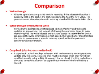
  • 52. Comparison • Write-through – All write operations are passed to main memory; if the addressed location is currently held in the cache, the cache is updated to hold the new value. The processor must slow down to main memory speed while the write takes place. • Write-through with buffered write – Here all write operations are still passed to main memory and the cache updated as appropriate, but instead of slowing the processor down to main memory speed the write address and data are stored in a write buffer which can accept the write information at high speed. The write buffer then transfers the data to main memory, at main memory speed, while the processor continues with its next task. • Copy-back (also known as write-back) – A copy-back cache is not kept coherent with main memory. Write operations update only the cache, so cache lines must remember when they have been modified (usually using a dirty bit on each line or block). If a dirty cache line is allocated to new data it must be copied back to memory before the line is reused. 52
  • 53. Memory Management • There are two principal approaches to memory management, called – Segmentation – Paging 53
  • 54. Segment • The simplest form of memory management allows an application to view its memory as a set of segments, where each segment contains a particular sort of information. • For instance – Code segment – Data segment – Stack segment 54
  • 56. Paging • In a paging memory management scheme both the logical and the physical address spaces are divided into fixed-size components called pages. • A page is usually a few kilobytes in size, but different architectures use different page sizes. 56
  • 58. ARM Assembly Language Programming • Data processing Instructions • Data Transfer Instructions • Control flow Instruction 58
  • 59. Data Processing Instructions • Simple register operands • Register movement operations • Comparison operations • Immediate Operands • Shifted register operands • Multiplies 59
  • 64. Immediate operands ADD r3, r3, #1 AND r8, r7, #FF 64
  • 67. Multiplies • Immediate second operands are not supported. • The result register must not be the same as the first source register. 67
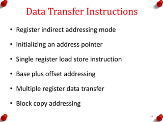
  • 68. Data Transfer Instructions • Register indirect addressing mode • Initializing an address pointer • Single register load store instruction • Base plus offset addressing • Multiple register data transfer • Block copy addressing 68
  • 71. Single register load store instruction 71
  • 72. Single register load store instruction 72
  • 73. Base plus offset Addressing LDR r0, [r1,#4] ; r0= mem32[r1+4] LDR r0, [r1,#4]! ; r0= mem32[r1+4] ; r1=r1+4 73
  • 74. Base plus offset Addressing 74
  • 75. Base plus offset Addressing 75
  • 76. Multiple register data transfer 76
  • 78. Control Flow Instructions • Branch Instructions • Conditional Branches 78
  • 81. Conditional Branches Z=1 C=1 C=0 N=1 N=0 V=1 V=0 C=1 & Z=0 C=0 & Z=1 N=V N!=V Z=0 & N=V Z=1 & N!=V Z=0 81
  • 83. Examples If ((a==b )&& (c==d)) { e++; } CMP r0, r1 CMPEQ r2, r3 ADDEQ r4, r4, #1 83
  • 84. Examples • Write a program to print ‘Helloworld’ 84
  • 85. Examples • Move content of table 1 to table 2 and print 85
  • 86. Examples • Printout r1 in Hexadecimal 86
  • 87. Examples • Output text string immediately following the CALL 87
  • 88. Architectural Support for Operating systems • ARM system control coprocessor • CP15 protection unit registers • CP15 MMU registers • ARM MMU architecture • Context switching • Input/Output 88
  • 89. ARM system control coprocessor • ARM system control coprocessor is an on-chip coprocessor, using coprocessor number 15 (CP15) • It controls the operation of the – On chip cache – Memory management – Protections unit – Write buffer – Prefetch buffer – Branch target cache – System configurations signals 89
  • 90. CP15 Protection Unit registers 90
  • 91. CP15 Protection Unit registers • Register 0 (ID Register) • Bits [3:0]  revision number, • bits [15:4] 3-digit part number • bits [23:16] architecture version (0 for version 3, 1 for version 4, 2 for version 4T, 4 for version 5T) • bits [31:24] ASCII code of an implementer's trademark 91
  • 92. CP15 Protection Unit registers • Register 1 (Configuration) • All bits are cleared on reset. • M  Protection unit, • C  data or unified cache, • W  write buffer, • B switches from little- to big-endian byte ordering, • I enables the instruction cache when this is separate from the data cache, • V causes the exception vectors to move to near the top of the address space, • S, Lck, F and Bnk are used to control the cache (on the ARM740T), and • nf and iA control various clock mechanisms (on the ARM940T). 92
  • 93. CP15 Protection Unit registers • Register 2 (Cache Control) • It controls the cache ability of the eight individual protection regions • Bit 0 enables the cache for loads within region 0, • Bit 1 likewise for region 1, and so on. • The ARM940T has separate protection units on its instruction and data ports • Cop2 is used to determine which unit is accessed: • Cop2 = 0 gives access to the protection unit on the data port; • Cop2 = 1 gives access to the protection unit on the instruction port 93
  • 94. CP15 Protection Unit registers • Register 3 (Write Buffer Control) • It defines whether or not the write buffer should be used for each of the protection regions. • The ARM940T instruction port is read-only, • The write buffer can only be enabled for the data port • and so Cop2 should always be zero 94
  • 95. CP15 Protection Unit registers • Register 5 (Access Permission) • 00  No access • 01  Privileged modes • 10  Privileged full access and user read only • 11  Full access. • Again the ARM940T uses the Cop2 field to differentiate  1 instruction protection units  0  data protection units. 95
  • 96. CP15 Protection Unit registers • Register 6 (Region Base and Size) • It defines the start address and size of each of the eight regions. 96
  • 97. CP15 Protection Unit registers • Register 7 (Cache Operation) – It controls various cache operations and – its operation is different for the ARM740T and the ARM940T. • Register 9 (Cache Lock Down) – It is used in the ARM940T to lock down areas of the cache. 97
  • 98. CP15 Protection Unit registers • Register 15 (Test) – It is used in the ARM940T to modify the cache allocation algorithm from random to round-robin. – This is intended for use only during silicon production testing. 98
  • 100. CP15 MMU Registers • Register 0 • Bits [3:0]  revision number, • bits [15:4] 3-digit part number • bits [23:16] architecture version (0 for version 3, 1 for version 4) • bits [31:24] ASCII code of an implementer's trademark 100
  • 101. CP15 MMU Registers • Register 1 (Control) • All bits are cleared on reset. • M  MMUunit, • A  Address Alignment fault checking, • C data or unified cache • W  write buffer, • P  switches from 26 to 32 bit address range • L  switches to late abort timeing • B switches from little- to big-endian byte ordering, • S & R  modify the MMU system and ROM protection states • F  controls the external coprocessor communications • Z  enables branch prediction • I  enables the instruction cache when this is separate from the data cache, • V causes the exception vectors to move to near the top of the address space, • RR  enables cache replacement algorithm 101
  • 102. CP15 MMU Registers • Register 2 (Translation Table Base) • It contains the address of the start of the currently active first-level translation table 102
  • 103. CP15 MMU Registers • Register 3(Domain Access Control) 103
  • 104. CP15 MMU Registers • Register 5 (Fault Status) • It indicates the type of fault and the domain of the last data access that aborted. • D is set on a data breakpoint. 104
  • 105. CP15 MMU Registers • Register 6 (Fault Address) • It contains the address of the last data access that aborted. 105
  • 106. CP15 MMU Registers • Register 7 (Cache Operation) • It is used to perform a – Number of cache, – Write buffer, – Prefetch buffer and – Branch target cache clean and/or – Flush operations. • The data supplied should be either zero or a relevant virtual address. 106
  • 107. CP15 MMU Registers • Register 8 (TLB Operations) • It is used to perform a number of – TLB operations, – Flushing single entries or the whole TLB and – Supporting unified or separate instruction and data TLBs 107
  • 108. CP15 MMU Registers • Register 9 (Read Buffer Operation) – It is used to control the read buffer • Register 10 (TLB Lockdown) – It is used to control TLB lockdown functions • Register 13 (Process ID Mapping) – It is used to remap virtual addresses through a process ID register. 108
  • 109. ARM MMU Architecture • An MMU performs two primary functions: – It translates virtual addresses into physical addresses. – It controls memory access permissions, aborting illegal accesses. 109
  • 110. Memory Granularity • The units that can be used are: – Sections. • These are 1 Mbyte blocks of memory. – Large pages. • These are 64 Kbyte blocks of memory, and within a large page access control is applied to individual 16 Kbyte subpages. – Small pages. • These are 4 Kbyte blocks of memory, and within a small page access control is applied to individual 1 Kbyte subpages. – Tiny pages. • Some of the latest CPUs also support 1 Kbyte 'tiny' pages. 110
  • 111. Domains • Domain is a group of sections or pages which have particular access permission • The access control is based on two sorts of programs – Clients • Clients are users of domains and must observe the access permissions of the individual sections and pages that make up the domain. – Managers • Managers are the controllers of the domain and can bypass the access permissions of individual sections or pages 111
  • 112. Translation Process • First Translation fetch • Section Translation • Page Translation • Access Permissions 112
  • 118. Context Switching • When a process switch takes place, the context of the old process must be saved and that of the new process restored 118
  • 119. Context Switching • A process runs in a context, which is all the system state that must be established for the process to run correctly. • This state includes: – Processor's registers, – Program counter, – Stack pointer, and so on; – the values in the floating-point registers, – the translation tables in memory – Data values used by the process in memory. 119
  • 120. Memory mapped peripherals • A peripheral device, such as a serial line controller, contains a number of registers. • In a memory-mapped system, each of these registers appears like a memory location at a particular address. • A serial line controller may have a set of registers as follows: • A transmit data register (write only); • A receive data register (read only); • A control register (read/write); • RTS (request to send). • An interrupt enable register (read/write); • A status register (read only). 120
  • 121. Memory mapped Issues • Note that a memory-mapped peripheral register behaves differently from memory. • Two consecutive reads to the read data register will probably deliver different results even though no write to that location has taken place • Such locations are termed read-sensitive • Programs must be written very carefully where read- sensitive locations are involved, and, in particular, such locations must not be copied into a cache memory 121
  • 122. Reference 1. Peatman,J.B., “Design with PIC Micro Controllers”PearsonEducation,3rdEdition, 2004. 2. Furber,S., “ARM System on Chip Architecture” Addison Wesley trade Computer Publication, 2000 122

Editor's Notes

  • #13: Green psr bits are only in certain versions of the ARM architecture ALU status flags (set if "S" bit set, implied in Thumb state). Sticky overflow flag (Q flag) is set either when saturation occurs during QADD, QDADD, QSUB or QDSUB, or the result of SMLAxy or SMLAWx overflows 32-bits Once flag has been set can not be modified by one of the above instructions and must write to CPSR using MSR instruction to cleared PSRs split into four 8-bit fields that can be individually written: Control (c) bits 0-7 Extension (x) bits 8-15 Reserved for future use Status (s) bits 16-23 Reserved for future use Flags (f) bits 24-31 Bits that are reserved for future use should not be modified by current software. Typically, a read-modify-write strategy should be used to update the value of a status register to ensure future compatibility. Note that the T/J bits in the CPSR should never be changed directly by writing to the PSR (use the BX/BXJ instruction to change state instead). However, in cases where the processor state is known in advance (e.g. on reset, following an interrupt, or some other exception), an immediate value may be written directly into the status registers, to change only specific bits (e.g. to change mode). New ARM V6 bits now shown.
  • #14: Green psr bits are only in certain versions of the ARM architecture ALU status flags (set if "S" bit set, implied in Thumb state). Sticky overflow flag (Q flag) is set either when saturation occurs during QADD, QDADD, QSUB or QDSUB, or the result of SMLAxy or SMLAWx overflows 32-bits Once flag has been set can not be modified by one of the above instructions and must write to CPSR using MSR instruction to cleared PSRs split into four 8-bit fields that can be individually written: Control (c) bits 0-7 Extension (x) bits 8-15 Reserved for future use Status (s) bits 16-23 Reserved for future use Flags (f) bits 24-31 Bits that are reserved for future use should not be modified by current software. Typically, a read-modify-write strategy should be used to update the value of a status register to ensure future compatibility. Note that the T/J bits in the CPSR should never be changed directly by writing to the PSR (use the BX/BXJ instruction to change state instead). However, in cases where the processor state is known in advance (e.g. on reset, following an interrupt, or some other exception), an immediate value may be written directly into the status registers, to change only specific bits (e.g. to change mode). New ARM V6 bits now shown.
  • #16: This slide shows the registers visible in each mode - basically in a more static fashion than the previous animated slide that is more useful for reference. The main point to state here is the splitting of the registers in Thumb state into Low and High registers. ARM register banking is the minimum necessary for fast handling of overlapping exceptions of different types (e.g. ABORT during SWI during IRQ). For nested exceptions of the same type (e.g. re-entrant interrupts) some additional pushing of registers to the stack is required.