SlideShare a Scribd company logo
INTRODUCTION TO DATA LINK
LAYER
DONE BY:
NAME: Shashank HP
SJC Inititute of Technology
Data Communication – 18CS46
Physical layer
Gives services to
Receives services
from
OVERVIEW OF DLL
● The data link layer transforms the physical layer, a raw transmission
facility, to a link responsible for node-to-node communication.
● Specific responsibilities of the data link layer include framing,
addressing, flow control, error control and media access control
L
A
N
s
W
A
N
s
Network layer
Packetizing
Flow
control
Media
Access
control
Addressing
Error
control
Data Link Layer
DLL DESIGN
● Services Provided to the Network Layer:
The network layer wants to send packets to its neighbours without
worrying about the details of it in one piece.
● Framing:
Group the physical layer bit stream into units called frames. Frames are
nothing more than “packets” or “messages”. By convention , we use the term
“frames” when discussing DLL.
● Error Control:
Sender checksums the frame and transmits checksums together with data.
Receiver re-computes the checksum and compares it with the received
value.
● Flow control:
Prevent a fast sender from overwhelming a slower receiver.
SERVICES PROVIDED TO THE NETWORK LAYER
● The function of the data link layer is to
provide services to the network layer.
● The principal service is transferring data
from the network layer on the source
machine to the network layer on the
destination machine.
● The data link layer can be designed to offer
various services. The actual services offered
can vary from system.
FRAMING
● DLL translates the physical layer’s raw stream into discrete units (messages) called frames.
● How can the frame be transmitted so the receiver can detect frame boundaries? That is, how can the
receiver recognize the start and end of a frame?
○ Character Count.
○ Flag byte with Byte Stuffing.
○ Starting and ending flag with bit stuffing.
○ Encoding Violations.
FRAMING - CHARACTER COUNT
● The first framing method uses a field in the header to specify the number of characters in the frame. When
the data link layer at the destination sees the character count, it knows how many characters follow and
hence where the end of the frame is.
FRAMING - BYTE STUFFING
● Use reserved characters to indicate the start and end of a frame. For instance, use the
two-character sequence DLE STX(Data-Link Escape, Start of TeXt) to signal the beginning
of a frame, and the sequence DLE ETX(End of TeXt) to flag the frame’s end.
● The second framing method, Starting and ending character stuffing, gets around the
problem of resynchronization after an error by having each frame start with the
sequence DLE ETX.
● EXAMPLE: If the frame contained “A B DLE D E DLE”, the characters transmitted over
the channel would be “DLE STX A B DLE DLE D E DLE DLE DLE ETX”
FRAMING-BIT STUFFING
● This technique allows data frames to contain an arbitrary number of bits and allows character
codes with an arbitrary number of bits per character. Each frame begins and ends with a
special bit pattern, 01111110.
● Whenever the sender’s data link layer encounters five consecutive 1s in the data, it
automatically stuffs a 0 bit into the outgoing bit stream.
● This bit stuffing is analogous to byte stuffing ,in which an escape byte is stuffed into the
outgoing character stream before a flag byte in the data. When the receiver sees five
consecutive incoming 1 bits,followed by a 0 bit, it automatically destuffs (i.e deletes) the 0 bit.
PHYSICAL LAYER CODING VIOLATIONS
● This Framing Method is used only in those networks in which Encoding on the Physical
Medium contains some redundancy.
● Some LANs encode each bit of data by using two Physical Bits i.e. Manchester coding is
Used. Here, Bit 1 is encoded into high-low(10) pair and Bit 0 is encoded into low-high(01)
pair.
● The scheme means that every data bit has a transition in the middle, making it easy for
the receiver to locate the bit boundaries. The combinations high-high and low-low are not
used for data but are used for delimiting frames in some protocols.
ERROR CONTROL
There are many reasons such as noise, cross-talk etc., which may help data to get corrupted during
transmission. Error control is concerned with insuring that all frames are eventually delivered (possibly
in order) to destination.
Data-link layer uses some error control mechanism to ensure that frames (data bit streams) are
transmitted with certain level of accuracy. But to understand how errors is controlled, it is essential to
know what types of errors may occur.
Types of Errors
There may be three types of errors:
Single bit error
Multiple bits error
Burst error
Error Detection
Errors in the received frames are detected by means of Parity Check and Cyclic
Redundancy Check (CRC). In both cases, few extra bits are sent along with actual data
to confirm that bits received at other end are same as they were sent. If the counter-
check at receiver’ end fails, the bits are considered corrupted.
• Parity Check
One extra bit is sent along with the original bits to make number of 1s either even in case of even
parity, or odd in case of odd parity.
For example, if even parity is used and number of 1s is even then one bit with value 0 is added. This
way number of 1s remains even. If the number of 1s is odd, to make it even a bit with value 1 is
added.
● Cyclic Redundancy Check (CRC)
CRC is a different approach to detect if the received frame contains valid data. This technique
involves binary division of the data bits being sent. The divisor is generated using polynomials. The
sender performs a division operation on the bits being sent and calculates the remainder. Before
sending the actual bits, the sender adds the remainder at the end of the actual bits. Actual data bits
plus the remainder is called a codeword. The sender transmits data bits as codewords.
At the other end, the receiver
performs division operation on
codewords using the same CRC
divisor. If the remainder contains
all zeros the data bits are
accepted, otherwise it is
considered as there some data
corruption occurred in transit.
Error Correction
In the digital world, error correction can be done in two ways:
● Backward Error Correction When the receiver detects an error in the data received, it requests
back the sender to retransmit the data unit.
● Forward Error Correction When the receiver detects some error in the data received, it
executes error-correcting code, which helps it to auto-recover and to correct some kinds of
errors.
The first one, Backward Error Correction, is simple and can only be efficiently used where retransmitting is not expensive.
For example, fiber optics. But in case of wireless transmission retransmitting may cost too much. In the latter case,
Forward Error Correction is used.
To correct the error in data frame, the receiver must know exactly which bit in the frame is corrupted. To locate the bit in
error, redundant bits are used as parity bits for error detection. For example, we take ASCII words (7 bits data), then there
could be 8 kind of information we need: first seven bits to tell us which bit is error and one more bit to tell that there is no
error.
FLOW CONTROL
● Flow control deals with throttling the speed of the sender to match that of the receiver.
● Two Approaches:
○ Feedback-based flow control, the receiver send back information to the sender giving it permission
to send more data or atleast telling the sender how the receiver is doing.
○ rate -based flow control, the protocol has a built-in mechanism that limits the rate at which senders
may transmit data, without using feedback from the receiver.
● Various Flow Control schemes uses a common protocol that contains well-defined rules
about when a sender may transmit the next frame. These rules often prohibit frames from
being sent until the receiver has granted permission, either implicitly or explicitly.
Network Layer Features
With its standard functionalities, various features as:
● Quality of service management
● Load balancing and link management
● Security
● Interrelation of different protocols and subnets with different schema.
● Different logical network design over the physical network design.
● L3 VPN and tunnels can be used to provide end to end dedicated
connectivity.
THANK YOU!

More Related Content

What's hot (20)

PDF
IEEE standards 802.3.&802.11
Keshav Maheshwari
 
PPT
Layer 2 switching fundamentals(networking)
welcometofacebook
 
PPT
Data link layer
sbkbca
 
PPTX
Unit 4 UDP
Nivetha Palanisamy
 
PPTX
Data link layer elementry protocols
sabitha sairam
 
PPT
Chapter 4 data link layer
Naiyan Noor
 
PPTX
TCP & UDP ( Transmission Control Protocol and User Datagram Protocol)
Kruti Niranjan
 
PPTX
Physical layer OSI Model & Transmission Media
Mukesh Chinta
 
PPTX
Digital to digital
Dr. ABHISHEK K PANDEY
 
PPSX
Physical layer ppt
Najam Khattak
 
ODP
C I D R
colmbennett
 
PPTX
Network layer
Hasib Shaikh
 
PPT
Flow & Error Control
tameemyousaf
 
PPT
Ethernet
T Uppili Srinivasan
 
PPT
Data link control
Iffat Anjum
 
PPTX
Transport layer protocols : TCP and UDP
Kongu Engineering College, Perundurai, Erode
 
PPTX
Routing algorithms
Parameswaran Selvakumar
 
PPT
Mac sub layer
DIKSHA_LAHRANI
 
IEEE standards 802.3.&802.11
Keshav Maheshwari
 
Layer 2 switching fundamentals(networking)
welcometofacebook
 
Data link layer
sbkbca
 
Unit 4 UDP
Nivetha Palanisamy
 
Data link layer elementry protocols
sabitha sairam
 
Chapter 4 data link layer
Naiyan Noor
 
TCP & UDP ( Transmission Control Protocol and User Datagram Protocol)
Kruti Niranjan
 
Physical layer OSI Model & Transmission Media
Mukesh Chinta
 
Digital to digital
Dr. ABHISHEK K PANDEY
 
Physical layer ppt
Najam Khattak
 
C I D R
colmbennett
 
Network layer
Hasib Shaikh
 
Flow & Error Control
tameemyousaf
 
Data link control
Iffat Anjum
 
Transport layer protocols : TCP and UDP
Kongu Engineering College, Perundurai, Erode
 
Routing algorithms
Parameswaran Selvakumar
 
Mac sub layer
DIKSHA_LAHRANI
 

Similar to Introduction to data link layer (20)

PDF
Data Communication and Computer Networks unit 2
ShanmukhaRao35
 
PPTX
data link layer - Chapter 3
SakthiVinoth78
 
PPT
Jaimin chp-3 - data-link layer- 2011 batch
Jaimin Jani
 
PPTX
Computer networks unit three presentation
manidheergorikapudi
 
PDF
Lecture Notes Unit III The DataLink Layer
Murugan146644
 
PPTX
Data Link layer in computer netwroks.pptx
RAJASEKARAN G
 
PPTX
datalinklayermukesh-150130061041-conversion-gate01.pptx
lathass5
 
PDF
DLL
Laxma Reddy
 
PPTX
Unit 2
APARNA P
 
PPTX
Data Communication Unit - II Data Link Layer.pptx
durgakru
 
PPTX
Data link layer
Mukesh Chinta
 
PDF
datalinklayermukesh
TamiratDejene1
 
PPTX
Dcn ppt on data link layer
roma bora
 
PPT
Unit 2 ppt 3.ppt
Selvakanmani S
 
PPTX
U2CH1Data Link Layerxxxxxxxxxxxxxxxxx.pptx
k2w9psdb96
 
PPTX
Computer network coe351- part4- final
Taymoor Nazmy
 
PPTX
ACchapter 3-Part I Data Communication.pptx
abdisa767
 
PPTX
Computer Networks (Computer Engineering) Unit-3 Data Link Layer & its Protoco...
smitkagathara7
 
PDF
CN R16 -UNIT-3.pdf
Joshuaeeda1
 
PPTX
Data communication network ppt_Unit_4.pptx
BHAVYPATEL34
 
Data Communication and Computer Networks unit 2
ShanmukhaRao35
 
data link layer - Chapter 3
SakthiVinoth78
 
Jaimin chp-3 - data-link layer- 2011 batch
Jaimin Jani
 
Computer networks unit three presentation
manidheergorikapudi
 
Lecture Notes Unit III The DataLink Layer
Murugan146644
 
Data Link layer in computer netwroks.pptx
RAJASEKARAN G
 
datalinklayermukesh-150130061041-conversion-gate01.pptx
lathass5
 
Unit 2
APARNA P
 
Data Communication Unit - II Data Link Layer.pptx
durgakru
 
Data link layer
Mukesh Chinta
 
datalinklayermukesh
TamiratDejene1
 
Dcn ppt on data link layer
roma bora
 
Unit 2 ppt 3.ppt
Selvakanmani S
 
U2CH1Data Link Layerxxxxxxxxxxxxxxxxx.pptx
k2w9psdb96
 
Computer network coe351- part4- final
Taymoor Nazmy
 
ACchapter 3-Part I Data Communication.pptx
abdisa767
 
Computer Networks (Computer Engineering) Unit-3 Data Link Layer & its Protoco...
smitkagathara7
 
CN R16 -UNIT-3.pdf
Joshuaeeda1
 
Data communication network ppt_Unit_4.pptx
BHAVYPATEL34
 
Ad

Recently uploaded (20)

PDF
Avatar for apidays apidays PRO June 07, 2025 0 5 apidays Helsinki & North 2...
apidays
 
PPTX
apidays Helsinki & North 2025 - Vero APIs - Experiences of API development in...
apidays
 
PPT
Growth of Public Expendituuure_55423.ppt
NavyaDeora
 
PPTX
apidays Helsinki & North 2025 - Running a Successful API Program: Best Practi...
apidays
 
PPTX
Module-5-Measures-of-Central-Tendency-Grouped-Data-1.pptx
lacsonjhoma0407
 
PPTX
apidays Munich 2025 - Building Telco-Aware Apps with Open Gateway APIs, Subhr...
apidays
 
PDF
Early_Diabetes_Detection_using_Machine_L.pdf
maria879693
 
PPTX
Exploring Multilingual Embeddings for Italian Semantic Search: A Pretrained a...
Sease
 
PPT
Data base management system Transactions.ppt
gandhamcharan2006
 
PPTX
apidays Helsinki & North 2025 - API access control strategies beyond JWT bear...
apidays
 
PPTX
apidays Singapore 2025 - Designing for Change, Julie Schiller (Google)
apidays
 
PPTX
apidays Helsinki & North 2025 - Agentic AI: A Friend or Foe?, Merja Kajava (A...
apidays
 
PDF
Data Chunking Strategies for RAG in 2025.pdf
Tamanna
 
PDF
Context Engineering for AI Agents, approaches, memories.pdf
Tamanna
 
PDF
R Cookbook - Processing and Manipulating Geological spatial data with R.pdf
OtnielSimopiaref2
 
PPTX
Climate Action.pptx action plan for climate
justfortalabat
 
PPTX
apidays Singapore 2025 - From Data to Insights: Building AI-Powered Data APIs...
apidays
 
PDF
What does good look like - CRAP Brighton 8 July 2025
Jan Kierzyk
 
PPT
deep dive data management sharepoint apps.ppt
novaprofk
 
PDF
apidays Helsinki & North 2025 - REST in Peace? Hunting the Dominant Design fo...
apidays
 
Avatar for apidays apidays PRO June 07, 2025 0 5 apidays Helsinki & North 2...
apidays
 
apidays Helsinki & North 2025 - Vero APIs - Experiences of API development in...
apidays
 
Growth of Public Expendituuure_55423.ppt
NavyaDeora
 
apidays Helsinki & North 2025 - Running a Successful API Program: Best Practi...
apidays
 
Module-5-Measures-of-Central-Tendency-Grouped-Data-1.pptx
lacsonjhoma0407
 
apidays Munich 2025 - Building Telco-Aware Apps with Open Gateway APIs, Subhr...
apidays
 
Early_Diabetes_Detection_using_Machine_L.pdf
maria879693
 
Exploring Multilingual Embeddings for Italian Semantic Search: A Pretrained a...
Sease
 
Data base management system Transactions.ppt
gandhamcharan2006
 
apidays Helsinki & North 2025 - API access control strategies beyond JWT bear...
apidays
 
apidays Singapore 2025 - Designing for Change, Julie Schiller (Google)
apidays
 
apidays Helsinki & North 2025 - Agentic AI: A Friend or Foe?, Merja Kajava (A...
apidays
 
Data Chunking Strategies for RAG in 2025.pdf
Tamanna
 
Context Engineering for AI Agents, approaches, memories.pdf
Tamanna
 
R Cookbook - Processing and Manipulating Geological spatial data with R.pdf
OtnielSimopiaref2
 
Climate Action.pptx action plan for climate
justfortalabat
 
apidays Singapore 2025 - From Data to Insights: Building AI-Powered Data APIs...
apidays
 
What does good look like - CRAP Brighton 8 July 2025
Jan Kierzyk
 
deep dive data management sharepoint apps.ppt
novaprofk
 
apidays Helsinki & North 2025 - REST in Peace? Hunting the Dominant Design fo...
apidays
 
Ad

Introduction to data link layer

  • 1. INTRODUCTION TO DATA LINK LAYER DONE BY: NAME: Shashank HP SJC Inititute of Technology Data Communication – 18CS46
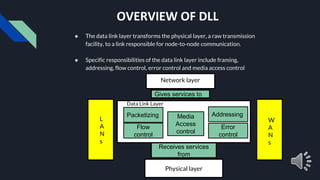
  • 2. Physical layer Gives services to Receives services from OVERVIEW OF DLL ● The data link layer transforms the physical layer, a raw transmission facility, to a link responsible for node-to-node communication. ● Specific responsibilities of the data link layer include framing, addressing, flow control, error control and media access control L A N s W A N s Network layer Packetizing Flow control Media Access control Addressing Error control Data Link Layer
  • 3. DLL DESIGN ● Services Provided to the Network Layer: The network layer wants to send packets to its neighbours without worrying about the details of it in one piece. ● Framing: Group the physical layer bit stream into units called frames. Frames are nothing more than “packets” or “messages”. By convention , we use the term “frames” when discussing DLL. ● Error Control: Sender checksums the frame and transmits checksums together with data. Receiver re-computes the checksum and compares it with the received value. ● Flow control: Prevent a fast sender from overwhelming a slower receiver.
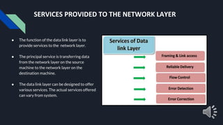
  • 4. SERVICES PROVIDED TO THE NETWORK LAYER ● The function of the data link layer is to provide services to the network layer. ● The principal service is transferring data from the network layer on the source machine to the network layer on the destination machine. ● The data link layer can be designed to offer various services. The actual services offered can vary from system.
  • 5. FRAMING ● DLL translates the physical layer’s raw stream into discrete units (messages) called frames. ● How can the frame be transmitted so the receiver can detect frame boundaries? That is, how can the receiver recognize the start and end of a frame? ○ Character Count. ○ Flag byte with Byte Stuffing. ○ Starting and ending flag with bit stuffing. ○ Encoding Violations.
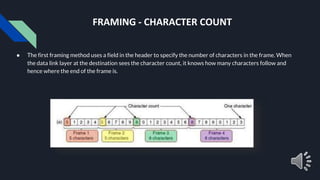
  • 6. FRAMING - CHARACTER COUNT ● The first framing method uses a field in the header to specify the number of characters in the frame. When the data link layer at the destination sees the character count, it knows how many characters follow and hence where the end of the frame is.
  • 7. FRAMING - BYTE STUFFING ● Use reserved characters to indicate the start and end of a frame. For instance, use the two-character sequence DLE STX(Data-Link Escape, Start of TeXt) to signal the beginning of a frame, and the sequence DLE ETX(End of TeXt) to flag the frame’s end. ● The second framing method, Starting and ending character stuffing, gets around the problem of resynchronization after an error by having each frame start with the sequence DLE ETX. ● EXAMPLE: If the frame contained “A B DLE D E DLE”, the characters transmitted over the channel would be “DLE STX A B DLE DLE D E DLE DLE DLE ETX”
  • 8. FRAMING-BIT STUFFING ● This technique allows data frames to contain an arbitrary number of bits and allows character codes with an arbitrary number of bits per character. Each frame begins and ends with a special bit pattern, 01111110. ● Whenever the sender’s data link layer encounters five consecutive 1s in the data, it automatically stuffs a 0 bit into the outgoing bit stream. ● This bit stuffing is analogous to byte stuffing ,in which an escape byte is stuffed into the outgoing character stream before a flag byte in the data. When the receiver sees five consecutive incoming 1 bits,followed by a 0 bit, it automatically destuffs (i.e deletes) the 0 bit.
  • 9. PHYSICAL LAYER CODING VIOLATIONS ● This Framing Method is used only in those networks in which Encoding on the Physical Medium contains some redundancy. ● Some LANs encode each bit of data by using two Physical Bits i.e. Manchester coding is Used. Here, Bit 1 is encoded into high-low(10) pair and Bit 0 is encoded into low-high(01) pair. ● The scheme means that every data bit has a transition in the middle, making it easy for the receiver to locate the bit boundaries. The combinations high-high and low-low are not used for data but are used for delimiting frames in some protocols.
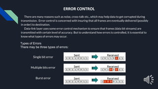
  • 10. ERROR CONTROL There are many reasons such as noise, cross-talk etc., which may help data to get corrupted during transmission. Error control is concerned with insuring that all frames are eventually delivered (possibly in order) to destination. Data-link layer uses some error control mechanism to ensure that frames (data bit streams) are transmitted with certain level of accuracy. But to understand how errors is controlled, it is essential to know what types of errors may occur. Types of Errors There may be three types of errors: Single bit error Multiple bits error Burst error
  • 11. Error Detection Errors in the received frames are detected by means of Parity Check and Cyclic Redundancy Check (CRC). In both cases, few extra bits are sent along with actual data to confirm that bits received at other end are same as they were sent. If the counter- check at receiver’ end fails, the bits are considered corrupted. • Parity Check One extra bit is sent along with the original bits to make number of 1s either even in case of even parity, or odd in case of odd parity. For example, if even parity is used and number of 1s is even then one bit with value 0 is added. This way number of 1s remains even. If the number of 1s is odd, to make it even a bit with value 1 is added.
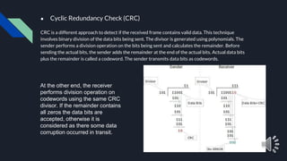
  • 12. ● Cyclic Redundancy Check (CRC) CRC is a different approach to detect if the received frame contains valid data. This technique involves binary division of the data bits being sent. The divisor is generated using polynomials. The sender performs a division operation on the bits being sent and calculates the remainder. Before sending the actual bits, the sender adds the remainder at the end of the actual bits. Actual data bits plus the remainder is called a codeword. The sender transmits data bits as codewords. At the other end, the receiver performs division operation on codewords using the same CRC divisor. If the remainder contains all zeros the data bits are accepted, otherwise it is considered as there some data corruption occurred in transit.
  • 13. Error Correction In the digital world, error correction can be done in two ways: ● Backward Error Correction When the receiver detects an error in the data received, it requests back the sender to retransmit the data unit. ● Forward Error Correction When the receiver detects some error in the data received, it executes error-correcting code, which helps it to auto-recover and to correct some kinds of errors. The first one, Backward Error Correction, is simple and can only be efficiently used where retransmitting is not expensive. For example, fiber optics. But in case of wireless transmission retransmitting may cost too much. In the latter case, Forward Error Correction is used. To correct the error in data frame, the receiver must know exactly which bit in the frame is corrupted. To locate the bit in error, redundant bits are used as parity bits for error detection. For example, we take ASCII words (7 bits data), then there could be 8 kind of information we need: first seven bits to tell us which bit is error and one more bit to tell that there is no error.
  • 14. FLOW CONTROL ● Flow control deals with throttling the speed of the sender to match that of the receiver. ● Two Approaches: ○ Feedback-based flow control, the receiver send back information to the sender giving it permission to send more data or atleast telling the sender how the receiver is doing. ○ rate -based flow control, the protocol has a built-in mechanism that limits the rate at which senders may transmit data, without using feedback from the receiver. ● Various Flow Control schemes uses a common protocol that contains well-defined rules about when a sender may transmit the next frame. These rules often prohibit frames from being sent until the receiver has granted permission, either implicitly or explicitly.
  • 15. Network Layer Features With its standard functionalities, various features as: ● Quality of service management ● Load balancing and link management ● Security ● Interrelation of different protocols and subnets with different schema. ● Different logical network design over the physical network design. ● L3 VPN and tunnels can be used to provide end to end dedicated connectivity.