SlideShare a Scribd company logo
Digital Communication
Dr. S. M. Gulhane
Professor & Head, Dept. of Electronics & Telecommunication Engineering,
Jawaharlal Darda Institute of Engineering & Technology, Yavatmal
Sant Gadge Baba Amravati University, Maharashtra, India
Unit-1 : Introduction to Digital Communication
1 1
0
0
1
1
0
1
1
0
0
0
1
Introduction to Digital
Communication
Content
• Communication System
• Elements of Digital Communication
• Line Coding
• Scrambling
Unit-1 : Introduction to Digital Communication
The Presentation is as per the syllabus of the subject ”Digital Communication” of B.E. VIth
Semester of Sant Gadge Baba Amravati University, Maharashtra, India
Dr. S.M.Gulhane JDIET,Yavatmal
1 Introduction
• The communication Process
Analog sources of information
• Voice, video, are analog continuous time signals
Digital sources of information
• Text, data files etc.
Dr. S.M.Gulhane JDIET,Yavatmal
Communication System
Three major parts
• Transmitter:
▪ process and modify the message signal into a form suitable
for efficient transmission over the channel
▪ amplification, filtering, modulation etc
• Communication channel:
▪ medium between transmitter and receiver
▪ provides the electrical connection between the transmitter
and receiver
▪ transmission line, an optical fiber, a wire, coaxial cable,
waveguide or a radio link
• Receiver :
▪ Recreate the original message from the degraded version
of the transmitted signal after propagation through the
channel.
Dr. S.M.Gulhane JDIET, Yavatmal
Degradation of the signal
Reasons
• Distortion of signal due to nonlinearities and/or
imperfection in the frequency response of the
channel
▪ channel acts as a filter to attenuate the signal and distort
its waveform.
▪ signal attenuation increases with the length of channel
▪ The waveform is distorted because of different amount of
attenuation and phase shift suffered by different
frequency components of the signal
• noise and interference picked up by the signal
while travelling through the channel
Dr. S.M.Gulhane JDIET,Yavatmal
Degradation of the signal
• Noise and signal distortion are two basic problems of
electrical communication.
• These problems set limit on the rate of communication
• The transmitter and receiver in communication system
should be carefully designed to avoid signal distortion and
minimize the effect of noise so that faithful reproduction of
the information is possible.
Dr. S.M.Gulhane JDIET,Yavatmal
Why Digital?
• It is difficult to distinguish the noise from the analog signal
• It is easy to distinguish the noise from a digital signal. Digital
receiver only need to make a threshold decision (‘0’ or ‘1’?)
No loss of signal quality: Complete clean-up and regeneration is
possible
Dr. S.M.Gulhane JDIET,Yavatmal
Why Digital?
 Advanced processing is possible, such as:
◦ Channel coding
◦ Source coding
◦ Encryption
◦ Multiplexing different users (TDMA, CDMA…)
◦ Multiplexing data from different sources (voice, video,
data, medical…)
◦ Lossless storing and retrieval
◦
◦ Many more advantages
Dr. S.M.Gulhane JDIET,Yavatmal
Communication Resources
• Transmitted power
• Channel bandwidth
• A general system design objective is to use these two
resources as efficiently as possible
• In most communication channels one resource may be
considered more important than the other.
• Accordingly we classify channels as power limited or band
limited.
• For e.g. telephone circuit is typically band limited channel
whereas space communication link or satellite channel is
typically power limited and mobile communication is both
power limited and band limited
Dr. S.M.Gulhane JDIET,Yavatmal
Communication Resources
• The goals of digital communication system are
▪ Transmission at high rate i.e. transmission of
message as fast as possible
▪ Error free transmission i.e. transmission should be
error free and accurate.
• The performance of digital communication
system is measured in terms of
▪ Probability of error in received signal
▪ Transmission rate
Dr. S.M.Gulhane JDIET,Yavatmal
Elements of Digital Communication
• Information source
• may either be analog or digital
▪ In digital comm. system it is the discrete information which is processed
and transmitted.
• Discrete information sources are characterized by
▪ Source alphabets: these are letters, characters, symbols or special
character available from the information source.
▪ Symbol rate: rate at which the information source generate source
alphabets. normally represented as symbols/ sec.
▪ Source alphabets probabilities: The rate of occurrence of each source
alphabet is different and hence the prob. of occurrence of each source
alphabets become one of most important property
▪ Entropy of the source sequence: the average information content per
symbol in a long message. It is denoted by H & unit is bits per symbol.
▪ Source information rate: It is defined as the product of the source entropy
& symbol rate & has the unit of bits per second. It is denoted by R.
Elements of Digital Communication
• Source encoder/decoder
▪ The function of source encoder is to efficiently represent the
discrete source (using the minimum possible number of bits)
▪ The source encoder encodes the source information into a digital
format for transmission
▪ The source encoder converts the symbol sequence into a binary
sequence by assigning code words to the symbol in the input
sequence.
▪ Codeword assigned may be
o Fixed or Variable
• The Source encoder is characterized by
▪ Codeword length: it is the no. of bits used to represent each codeword
▪ Block size: it is the maximum number of distinct codeword that the
encoder can represent.
▪ Average data rate: it is the average data rate available from the encoder.
▪ Efficiency of encoder: it is the actual o/p data rate compare to the
maximum achievable rate R.
Elements of Digital Communication
• Source encoder/decoder
▪ At the receiver the decoder converts the Binary o/p of the
channel into a symbol sequence
• Source encoder are vital in determining the
transmitted bit rate and the quality of the
recovered information
• The quality and transmission rate are two factors
that directly conflict each other.
• The lower is the bit rate the more is the signal
quality and vice versa.
Dr. S.M.Gulhane JDIET,Yavatmal
Elements of Digital Communication
• Channel encoder/decoder
▪ The channel encoder enables the receiver to correct error that occur
during transmission.
▪ To do so channel encoder add some redundant bit to the input bit
sequence.
▪ This extra bits carry no information but they are used by the decoder in
the receiver to detect and correct the error in the signal received.
▪ Addition of extra bit by the channel coding increases the bit rate hence
required more bandwidth for transmission. However it allows the
receiver to perform error detection and correction.
▪ Two methods
o Block coding
o Convolutional coding
• The Channel encoder is characterized by
▪ Methods of coding used
▪ Rate or efficiency of the coder
▪ Error control capabilities
▪ Complexity of the encoder Dr. S.M.Gulhane JDIET,Yavatmal
Elements of Digital Communication
• Modulator and demodulator
▪ The process of modulation convert the channel coded signal into
the format suitable for transmission over a communication
channel.
▪ The signal of binary bits from the channel coder is given to the
digital modulator which maps input binary sequence of 1’s and
0’s to the analog in order
o to match the freq. spectrum
o to minimize the effect of channel noise
o to provide the capability to multiplex many signals
o to overcome equipment limitation
Dr. S.M.Gulhane JDIET,Yavatmal
Introduction to Digital Communication
Line Coding
• The communication Process
how to represent digital data by using digital signals.?
• There are numerous ways we can convert a string of logical
1’s and 0’s to a sequence of pulses.
• Line coding involves converting a sequence of 1s and 0s to a
sequence of pulses suitable for transmission over a channel.
ADC
Analog message
1 0 1 1 0 1...
?
1
0
1 1
0
1
OR
1 1 1 1
0 0
Line Coding
• There are various ways of Line coding suitable for
▪ Different channel characteristics
▪ Different applications and
▪ Performance requirements.
Each line code has its own distinct properties
• The most desirable features that are considered while
choosing line codes are
• Zero DC content
• Enough Timing Content
• Small Bandwidth
• Small probability of error
• Good power efficiency
• Transparency
• Built-in error detection
Dr. S.M.Gulhane JDIET,Yavatmal
Desirable features of Line coding
• DC Content
▪ Signal obtained at the output of line coder may have dc component
in it
▪ DC levels are inherently wasteful of power.
▪ If a signal is to pass through an ac coupled lines (or ac coupling in
the transformers and repeaters) that does not allow the passage of
a dc component, the signal is distorted and may create errors in the
output.
▪ It is desirable to have zero dc in the waveform produced by a given
line code
• Bandwidth
• We need small BW in order to be able to send more signals in a
communication channel.
• Different encoding of data leads to different spectrum of the signal.
• The power spectrum and bandwidth of the transmitted signal should
be matched with the spectrum of the channel to avoid distortion.
• The transmission bandwidth needs to be sufficiently small compared
to the channel bandwidth so that inter-symbol interference will not
be a problem. .
Desirable features of Line coding
• Timing Content
▪ The waveform produced by a given line code should contain enough
timing information so that the receiver can extract the clock
information and decode the received signal properly.
▪ The timing content should be independent of source characteristics
▪ A long string of 1s or 0s may result in loss of timing at the receiver.
• Built-in error detection
▪ It is desirable for the line coder to have error detection capability.
• Transparency
▪ It should be possible to transmit every signal sequence correctly
regardless of the patterns of 1s and 0s.
• Probability of error
▪ The average error probability should be as small as possible.
▪ The lower probability of error makes the line code more reliable.
• In addition complexity and economy are the determining
factors for the choice of line coder.
Line Coding Techniques
• Generally there are 2 group of line codes
• Level codes
They are independent of the past data and they carry information on
their voltage level, They are further categorized as
▪ Unipolar: Only one polarity is used.( + or -)
▪ Polar: Both voltage levels are used
▪ Bipolar: Uses three levels: positive, zero, and negative.
They are further classified as
▪ RZ: The pulse level will go to zero for a portion of bit duration
▪ NRZ: The pulse level remains constant during the bit duration
• Transition codes
The current bit level depends on the previous levels. These codes have
memory
Dr. S.M.Gulhane JDIET,Yavatmal
Line Coding Techniques
Dr. S.M.Gulhane JDIET,Yavatmal
Level Coding
Transition Coding
Bi-phase Coding
BNZS
HDBn
CMI Miller (DM)
Unipolar NRZ
• In unipolar encoding, only one polarity of voltage level is
used
• a binary ‘1’ is represented by positive voltage level and a
binary ‘0 is represented by zero voltage.
• 0 1 0 0 1 1 1 0 0 0 0
Unipolar NRZ
The power spectral density for a unipolar NRZ signal with pulse
duration of Tb is
Dr. S.M.Gulhane JDIET,Yavatmal
Unipolar NRZ
Unipolar NRZ
The power spectral density contain a delta function at dc.
Advantages
• Relatively easy to generate the signal (TTL/CMOS) from a single power
supply
• Relatively low bandwidth of R Hz.
Drawback
• A dc component is always present corresponding to a waste of
transmission power.
• It has a large power spectral density near dc.
• Poor clock recovery: A long stream of 0s or 1s will cause a loss of clock
signal.
• Has no error detection capability
• Poor error rate performance
• This line code is mostly used in magnetic tape recording.
Dr. S.M.Gulhane JDIET,Yavatmal
Unipolar RZ
• In this line code, a binary ‘1’ is represented by nonzero
voltage level for half of the bit period and a zero voltage
level for rest of the bit duration. A binary ‘0 is represented
by zero voltage level for the entire bit duration.
Unipolar RZ
The power spectral density for a unipolar RZ signal with a pulse
duration of Tb/2 is
Dr. S.M.Gulhane JDIET,Yavatmal
Unipolar RZ
Dr. S.M.Gulhane JDIET,Yavatmal
Unipolar RZ
Advantages
• Ease of generation, requires only one power supply
• Good clock recovery - periodic impulses at f = n/Tb can be used for
clock recovery.
Drawback
• The first null bandwidth is 2R Hz. So the bandwidth requirement is
higher than NRZ
• Content significant dc component
• The spectrum is not negligible near dc
• Has no error detection capability
• Poor error rate performance
This code is mostly used in baseband data transmission and
magnetic tape recording
Dr. S.M.Gulhane JDIET,Yavatmal
Polar NRZ
• Polar encoding uses two voltage levels (positive and
negative).
• Encoding rule:
▪ A binary 1 is represented by a positive voltage +V and a
binary 0 is represented by the negative voltage –V over the
full bit period.
▪ Alternately, a 1 is represented by a -V and a binary 0 is
represented by +V, without changing the spectral
characteristics and performance.
1 0 1 1 0 0 0 0 1 0 1
Polar NRZ
Polar NRZ
• The power spectral density for a polar NRZ signal with a
pulse duration of Tb is
Polar NRZ
• Advantages
▪ Low bandwidth R Hz
▪ Relatively easy to generate the signal but requires dual supply voltages.
▪ Bit error probability performance is superior to other line encoding
schemes.
• Disadvantages
▪ No error detection capability
▪ It has a large power spectral density near dc.
▪ Poor clock recovery: A long string of 1s and 0s will cause a loss of clock
signal.
▪ Two power supplies required
Polar RZ
• A 1 bit is represented by positive-to-zero and a 0 bit by
negative-to-zero.
1 0 1 1 0 0 0 0 1 0 1
• Advantage:
▪ Ensure synchronization since there is a signal change for each bit.
The receiver can use these changes to build up, update and
synchronize its clock.
▪ No dc component
• The main disadvantage of RZ is that it requires two
signal changes to encode one bit and therefore occupies
more bandwidth.
Polar RZ
Bipolar Encoding
• Bipolar encoding uses three levels: positive, zero, and
negative.
• In bipolar encoding the 1’s are represented by
alternating positive and negative voltages the binary 0s
are represented by zero level.
• This line coding is often called as Alternate Mark
Inversion (AMI) since 1’s (marks) are represented by
alternating positive and negative pulses. The word mark
comes from telegraphy and it means 1.
• This code is also referred as pseudoternary since three
different levels are used.
Bipolar Encoding
Bipolar NRZ
Bipolar RZ
Bipolar RZ
Bipolar Encoding
• Advantages
▪ Has no dc component
▪ capable of recovering clock information - the clock signal can
be easily extracted by converting the bipolar RZ signal to a
unipolar RZ signal using full-wave rectification.
▪ capable of single error detection since a single error will cause
a violation (the reception of 2 or more consecutive 1s with the
same polarity)
▪ Low bandwidth requirements R Hz
▪ good error probability
• Disadvantages
▪ A long string of zeros could result in loss of clock signal
▪ it needs twice much power as unipolar
▪ Two power supplies are required for generation
▪ The receiver has to distinguish between 3 logic levels
AMI code is well known for its use in telephony. This code has
memory. It is type of transition code.
Biphase (Split-phase, Twined-Binary) Coding
• In this coding pulses with 00 and 1800 phase are used
▪ Manchester and differential Manchester Coding are the two
common Bi-phase techniques
• Encoding rule for Manchester coding:
▪ A binary 1 is represented by a pulse that has positive voltage for
first half of the bit duration and negative voltage for second half of
the bit duration.
▪ A binary 0 is represented by a pulse that has negative voltage for
first half of the bit duration and positive voltage for second half of
the bit duration.
• In this line code transitions occur at the middle of each bit. A high to
low transition represents a 1 and a low to high transition represents a
0 or vice versa.
• 1 is represented by-->
• 0 is represented by--> Bit length
Manchester Coding
1 0 1 1 0 0 0 0 1 0 1
The power spectral density for a Manchester signal with
pulse duration of Tb/2 is
Manchester Coding
• Advantages:
▪ Zero DC because of half positive/half negative pulses
▪ Transparent: string of 1’s and 0’s will not affect DC levels
▪ Mid bit transitions are always present making it easy to extract
timing information
▪ Bit changes at the Middle (mid bit Transition) serves as a clocking
mechanism.
▪ Has good error rate performance
• Disadvantage
▪ Require larger Bandwidth
▪ Has no error detection capability
• It is well known for use in Ethernet
Dr. S.M.Gulhane JDIET,Yavatmal
Differential Manchester Encoding
• Encoding Rule:
▪ Use Bi-phase coding
▪ 0 represented by no transition
▪ 1 represented by transition
This results in presence or absence of transition at the beginning of the bit
• In differential Manchester encoding, the presence (0) or
absence (1) of transition at the beginning of the interval is
used to identify the bit.
• The transition at the middle of the bit is used only for
synchronization.
• The bit representation is defined by the inversion or non-
inversion at the beginning of the bit.
Frequency Spectrum
Dr. S.M.Gulhane JDIET,Yavatmal
BNZS (Binary N Zero Substitution) Code
• Bipolar code AMI has many desirable properties, but its major limitation
is that a long stream of zeros can lead to loss of clock signal and timing
jitter.
• BNZS attempts to improve AMI by substituting a special code of length
N for strings of N zeros.
• This special code look like binary 1s but purposely produce violations of
the AMI pulse convention.
• The special code is chosen such that the desirable properties of AMI is
retained.
• The special code contain pulses facilitating synchronization even when
long string of zeros occurs.
• Three commonly used BNZS codes in telephony are B3ZS, B6ZS and
B8ZS
Dr. S.M.Gulhane JDIET,Yavatmal
HDBn (High Density Binary)
• High density binary n line code is just like BNZS with the
following modification:
• A string of N+1 consecutive zeros are replaced by a special
code of length N+1 containing AMI violation.
• Most commonly used HDBn code is HDB3 where a string of 4
zeros is replaced by a special code
• A string of 4 zeros is replaced by either 000V or 100V. V is a
binary 1 with the sign chosen to violate the AMI rule. This will
let the receiver to know about the substitution.
• corresponding HDB3 coding for sequence 10110000101.
V
1 0 1 1 0 0 0 0 1 0 1
Must alternate in polarity
HDBn (High Density Binary)
• B00V is used when there are an even number of ones
following the last special sequence and 000V is used when
there are an odd number of ones following the last special
sequence.
▪ where V’s are bipolar violation and B’s are valid bipolar signals.
• Consecutive V pulses alternate in sign to avoid dc wander.
• Because violation just happens at the fourth bit of the special
code , it can be easily detected and will be replaced by a zero
at the receiver.
• It is also capable of error detecting because a sign error would
make the number of bipolar pulses between violations even
instead of odd.
Dr. S.M.Gulhane JDIET,Yavatmal
HDBn (High Density Binary)
Dr. S.M.Gulhane JDIET,Yavatmal
Coded Mark Inversion(CMI)
• CMI is a modified polar NRZ code. Pulses corresponding to 1’s
are encoded as an NRZ pulse with alternate polarity +V or –V
and binary 0’s are encoded with midbit transition.
• Spectrum is similar to bipolar-NRZ but has a clock component
at the pulse rate
• Has no dc component
1 0 1 1 0 0 0 0 1 0 1
• A ‘1’ is represented by a transition at the middle of the bit and
a ‘0’ is represented by no transition unless it is followed by
another zero.
• In this case another transition will occur at the end of the bit
duration between 2 ‘0s’.
1 0 1 1 0 0 0 1 1 1 0
Miller code (DM)
Miller code (Delay Modulation)
• Advantages
▪ Has no dc component
▪ Majority of signal energy lies in frequencies less than 0.5R.
▪ Low bandwidth requirements R Hz
▪ good timing information recovery. The clock frequency is
embedded in the code for all symbol sequences
▪ good error probability
• Disadvantages
▪ not capable of error detecting
▪ Small spectrum at dc may not be acceptable for some
transmission channels
Attractive for magnetic recording and PSK signaling
Dr. S.M.Gulhane JDIET,Yavatmal
Introduction to Digital Communication
Line coding review
In general, there is no optimum waveform choice for all digital
transmission systems.
• Return-to-zero (RZ) waveforms may be attractive when the
bandwidth is available. Because RZ waveforms always have two level
transitions per symbol interval, symbol timing recovery can easily be
achieved.
• For bandwidth-efficient systems, non-return-to- zero (NRZ)
waveforms are more attractive. However, long strings of ones or
zeros should be avoided to allow accurate recovery of symbol timing.
• Polar or unipolar signals are found in most digital circuits, but they
may have a nonzero dc level.
• Bipolar and Manchester signals will always have a zero dc level
regardless of the data sequence.
Dr. S.M.Gulhane JDIET,Yavatmal
Line coding review
Scrambling
• Scrambler may be used as a data randomizer or for
encryption
• As a randomizer, it makes the data more random by
removing long strings of 1’s or 0’s. thus helpful in timing
extraction.
• As an encryption, scramblers may be used for preventing
unauthorized access to the data
• The simplest form of scrambling is to add a long PN sequence
to the data sequence (via modulo 2 addition).
• A scrambler consist of a feedback register. A corresponding
descrambler has a feed forward register
• In receiver, descrambling is done using the same PN
sequence.
• A scrambler/descrambler is defined by the polynomial of its
LFSR and its initial state.
Dr. S.M.Gulhane JDIET,Yavatmal
Polynomial is 1+x2+x5
T = S  FT = S  D2T  D5T
R= T  FT = S  FT  FT = S
In scrambler T is operated by F and added to S
F- stands for operator, where F= D2  D5
- D denotes the effect of delaying sequence by one
- DkT - represents sequence T delayed by k bits
RT’TS
Dr. S.M.Gulhane JDIET,Yavatmal
Scrambling
Scrambling Example
• Exercise: 100000000000
• Scrambler
• Descrambler
S
T
S T
S’T’S’
T’
initial state
Scrambling Example
• Realize the scrambler and descrambler with a PN Sequence LSFR polynomial 1+x3+x5
and determine the sequence obtained at the output of scrambler and descrambler for the
input sequence 11010
• Descrambler
S’
1 1 0 0 1
5
3
4
2
1
+
+ TS
0 0 0 0 0 1
0 0 0 1 1 0
0 0 0 0 1 1
0 0 1 1 0 0
0 1 1 0 0 1
0 1 0 1 1
initial state
5
3
4
2
1
T
0 0 0 0 0 1
0 0 0 1 1 0
0 0 0 0 1 1
0 0 1 1 0 1
0 1 1 0 1 0
1 0 0 1 1 1 1 0 1 0
Dr. S.M.Gulhane JDIET,Yavatmal
Scrambling Example
• Realize the scrambler and descrambler with a PN Sequence LSFR polynomial 1+x3+x5
and determine the sequence obtained at the output of scrambler and descrambler for the
input sequence 11010
S’
0 1 0 1 0
5
3
4
2
1
+
+ TS
0 0 0 0 0 0
0 0 0 0 1 0
0 0 0 0 0 1
0 0 0 1 0 1
0 0 1 0 1 0
1 1 0 1 0
initial state
5
3
4
2
1
T
0 0 0 0 0 1
0 0 0 0 1 0
0 0 0 0 0 1
0 0 0 1 0 1
0 0 1 0 1 0
0 1 0 1 0 0 1 0 1 1
Scrambler
Descrambler
Thus the sequence is 11011
Thank You…..

More Related Content

What's hot (20)

PPT
Dsss final
AJAL A J
 
PPTX
Tdm and fdm
shyamaliamale
 
PPTX
Chap 5 (small scale fading)
asadkhan1327
 
PPT
Introduction to communication system lecture1
Jumaan Ally Mohamed
 
PPTX
Digital Modulation Techniques ppt
Pankaj Singh
 
PPTX
Multirate DSP
@zenafaris91
 
PPTX
Power delay profile,delay spread and doppler spread
Manish Srivastava
 
PPT
Modulation Techniques for Mobile Radio
METHODIST COLLEGE OF ENGG & TECH
 
PPT
Pulse code modulation
Naveen Sihag
 
PPTX
Digital modulation techniques...
Nidhi Baranwal
 
PPTX
cellular concepts in wireless communication
asadkhan1327
 
PPT
Delta Modulation
Nahian Ahmed
 
PPTX
Pulse code modulation (PCM)
Mahima Shastri
 
PPT
1 . introduction to communication system
abhijitjnec
 
PPTX
Digital Communication Unit 1
Anjuman College of Engg. & Tech.
 
PPT
Time Division Multiplexing
Spandit Lenka
 
PPTX
OFDM
Suman Yadav
 
PPTX
Digital t carriers and multiplexing power point (laurens)
Laurens Luis Bugayong
 
Dsss final
AJAL A J
 
Tdm and fdm
shyamaliamale
 
Chap 5 (small scale fading)
asadkhan1327
 
Introduction to communication system lecture1
Jumaan Ally Mohamed
 
Digital Modulation Techniques ppt
Pankaj Singh
 
Multirate DSP
@zenafaris91
 
Power delay profile,delay spread and doppler spread
Manish Srivastava
 
Modulation Techniques for Mobile Radio
METHODIST COLLEGE OF ENGG & TECH
 
Pulse code modulation
Naveen Sihag
 
Digital modulation techniques...
Nidhi Baranwal
 
cellular concepts in wireless communication
asadkhan1327
 
Delta Modulation
Nahian Ahmed
 
Pulse code modulation (PCM)
Mahima Shastri
 
1 . introduction to communication system
abhijitjnec
 
Digital Communication Unit 1
Anjuman College of Engg. & Tech.
 
Time Division Multiplexing
Spandit Lenka
 
Digital t carriers and multiplexing power point (laurens)
Laurens Luis Bugayong
 

Similar to Introduction to Digital Communication (20)

PDF
Data Communication & Computer Networks:Digital Signal Encoding
Dr Rajiv Srivastava
 
PDF
lect-1-introduction in digital communication
hassan2lsaadi
 
PPTX
Unit-2-04-digitatoDogitalconversion.pptx
Shilpachaudhari10
 
PPT
Lecture 08
Sehrish Rafiq
 
PDF
Mobile & Satellite Communications Overview of Digital Communication Systems
pangunpark
 
PPTX
Basic block diagram.pptfyr6r5e5ee5tr68t6ryfyifty
SHASHANK787429
 
PPT
Digital Communications 1167236_634502156284084624.ppt
hardiktank87
 
PPT
Digital Communication Lecture module - 1
SaralaT3
 
PPTX
Digital communication system
babak danyal
 
PPT
digital-communication-lecture-1 (1).ppt
Kevin317696
 
PDF
Ilovepdf merged
xyxz
 
PPTX
1.1Information & Coding Theory:Communication System.pptx
logeswarisaravanan
 
PDF
Communication Networks II
anishgoel
 
PPT
CCN
NICE
 
PPTX
Communication Networks Ii
anishgoel
 
PPT
communication system ch1
moeen khan afridi
 
PPTX
DC NOTES.pptx
AzhagesvaranTamilsel
 
PPT
1630944221ghfgthgfxcffcbcfgbfcgfdgfccgfd.ppt
LakshmishaRALakshmis
 
PPT
A communication system is a framework that enables the transfer of informatio...
FawadKhanFacultyEEDB
 
Data Communication & Computer Networks:Digital Signal Encoding
Dr Rajiv Srivastava
 
lect-1-introduction in digital communication
hassan2lsaadi
 
Unit-2-04-digitatoDogitalconversion.pptx
Shilpachaudhari10
 
Lecture 08
Sehrish Rafiq
 
Mobile & Satellite Communications Overview of Digital Communication Systems
pangunpark
 
Basic block diagram.pptfyr6r5e5ee5tr68t6ryfyifty
SHASHANK787429
 
Digital Communications 1167236_634502156284084624.ppt
hardiktank87
 
Digital Communication Lecture module - 1
SaralaT3
 
Digital communication system
babak danyal
 
digital-communication-lecture-1 (1).ppt
Kevin317696
 
Ilovepdf merged
xyxz
 
1.1Information & Coding Theory:Communication System.pptx
logeswarisaravanan
 
Communication Networks II
anishgoel
 
CCN
NICE
 
Communication Networks Ii
anishgoel
 
communication system ch1
moeen khan afridi
 
DC NOTES.pptx
AzhagesvaranTamilsel
 
1630944221ghfgthgfxcffcbcfgbfcgfdgfccgfd.ppt
LakshmishaRALakshmis
 
A communication system is a framework that enables the transfer of informatio...
FawadKhanFacultyEEDB
 
Ad

More from Dr. Sanjay M. Gulhane (7)

PDF
MOSFET....complete PPT
Dr. Sanjay M. Gulhane
 
PDF
E- MOSFET
Dr. Sanjay M. Gulhane
 
PDF
Field Effect Transistor
Dr. Sanjay M. Gulhane
 
PPT
Digital Communication: Channel Coding
Dr. Sanjay M. Gulhane
 
PPT
Digital Communication: Information Theory
Dr. Sanjay M. Gulhane
 
PDF
Course Content of 6ET3 Digital communication
Dr. Sanjay M. Gulhane
 
PDF
How to carry out research work : Tips for beginners
Dr. Sanjay M. Gulhane
 
MOSFET....complete PPT
Dr. Sanjay M. Gulhane
 
Field Effect Transistor
Dr. Sanjay M. Gulhane
 
Digital Communication: Channel Coding
Dr. Sanjay M. Gulhane
 
Digital Communication: Information Theory
Dr. Sanjay M. Gulhane
 
Course Content of 6ET3 Digital communication
Dr. Sanjay M. Gulhane
 
How to carry out research work : Tips for beginners
Dr. Sanjay M. Gulhane
 
Ad

Recently uploaded (20)

PDF
67243-Cooling and Heating & Calculation.pdf
DHAKA POLYTECHNIC
 
PPTX
Ground improvement techniques-DEWATERING
DivakarSai4
 
PPTX
FUNDAMENTALS OF ELECTRIC VEHICLES UNIT-1
MikkiliSuresh
 
PDF
Machine Learning All topics Covers In This Single Slides
AmritTiwari19
 
PPTX
Precedence and Associativity in C prog. language
Mahendra Dheer
 
PDF
2010_Book_EnvironmentalBioengineering (1).pdf
EmilianoRodriguezTll
 
PDF
SG1-ALM-MS-EL-30-0008 (00) MS - Isolators and disconnecting switches.pdf
djiceramil
 
PPTX
Online Cab Booking and Management System.pptx
diptipaneri80
 
PDF
CAD-CAM U-1 Combined Notes_57761226_2025_04_22_14_40.pdf
shailendrapratap2002
 
PPTX
MSME 4.0 Template idea hackathon pdf to understand
alaudeenaarish
 
PPTX
ENSA_Module_7.pptx_wide_area_network_concepts
RanaMukherjee24
 
PDF
settlement FOR FOUNDATION ENGINEERS.pdf
Endalkazene
 
PDF
Advanced LangChain & RAG: Building a Financial AI Assistant with Real-Time Data
Soufiane Sejjari
 
PPTX
Water resources Engineering GIS KRT.pptx
Krunal Thanki
 
PDF
Air -Powered Car PPT by ER. SHRESTH SUDHIR KOKNE.pdf
SHRESTHKOKNE
 
DOCX
SAR - EEEfdfdsdasdsdasdasdasdasdasdasdasda.docx
Kanimozhi676285
 
PDF
All chapters of Strength of materials.ppt
girmabiniyam1234
 
PPTX
ETP Presentation(1000m3 Small ETP For Power Plant and industry
MD Azharul Islam
 
PDF
4 Tier Teamcenter Installation part1.pdf
VnyKumar1
 
PPTX
Information Retrieval and Extraction - Module 7
premSankar19
 
67243-Cooling and Heating & Calculation.pdf
DHAKA POLYTECHNIC
 
Ground improvement techniques-DEWATERING
DivakarSai4
 
FUNDAMENTALS OF ELECTRIC VEHICLES UNIT-1
MikkiliSuresh
 
Machine Learning All topics Covers In This Single Slides
AmritTiwari19
 
Precedence and Associativity in C prog. language
Mahendra Dheer
 
2010_Book_EnvironmentalBioengineering (1).pdf
EmilianoRodriguezTll
 
SG1-ALM-MS-EL-30-0008 (00) MS - Isolators and disconnecting switches.pdf
djiceramil
 
Online Cab Booking and Management System.pptx
diptipaneri80
 
CAD-CAM U-1 Combined Notes_57761226_2025_04_22_14_40.pdf
shailendrapratap2002
 
MSME 4.0 Template idea hackathon pdf to understand
alaudeenaarish
 
ENSA_Module_7.pptx_wide_area_network_concepts
RanaMukherjee24
 
settlement FOR FOUNDATION ENGINEERS.pdf
Endalkazene
 
Advanced LangChain & RAG: Building a Financial AI Assistant with Real-Time Data
Soufiane Sejjari
 
Water resources Engineering GIS KRT.pptx
Krunal Thanki
 
Air -Powered Car PPT by ER. SHRESTH SUDHIR KOKNE.pdf
SHRESTHKOKNE
 
SAR - EEEfdfdsdasdsdasdasdasdasdasdasdasda.docx
Kanimozhi676285
 
All chapters of Strength of materials.ppt
girmabiniyam1234
 
ETP Presentation(1000m3 Small ETP For Power Plant and industry
MD Azharul Islam
 
4 Tier Teamcenter Installation part1.pdf
VnyKumar1
 
Information Retrieval and Extraction - Module 7
premSankar19
 

Introduction to Digital Communication

  • 1. Digital Communication Dr. S. M. Gulhane Professor & Head, Dept. of Electronics & Telecommunication Engineering, Jawaharlal Darda Institute of Engineering & Technology, Yavatmal Sant Gadge Baba Amravati University, Maharashtra, India Unit-1 : Introduction to Digital Communication 1 1 0 0 1 1 0 1 1 0 0 0 1 Introduction to Digital Communication
  • 2. Content • Communication System • Elements of Digital Communication • Line Coding • Scrambling Unit-1 : Introduction to Digital Communication The Presentation is as per the syllabus of the subject ”Digital Communication” of B.E. VIth Semester of Sant Gadge Baba Amravati University, Maharashtra, India Dr. S.M.Gulhane JDIET,Yavatmal
  • 3. 1 Introduction • The communication Process Analog sources of information • Voice, video, are analog continuous time signals Digital sources of information • Text, data files etc. Dr. S.M.Gulhane JDIET,Yavatmal
  • 4. Communication System Three major parts • Transmitter: ▪ process and modify the message signal into a form suitable for efficient transmission over the channel ▪ amplification, filtering, modulation etc • Communication channel: ▪ medium between transmitter and receiver ▪ provides the electrical connection between the transmitter and receiver ▪ transmission line, an optical fiber, a wire, coaxial cable, waveguide or a radio link • Receiver : ▪ Recreate the original message from the degraded version of the transmitted signal after propagation through the channel. Dr. S.M.Gulhane JDIET, Yavatmal
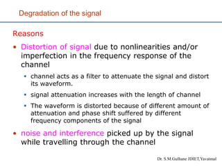
  • 5. Degradation of the signal Reasons • Distortion of signal due to nonlinearities and/or imperfection in the frequency response of the channel ▪ channel acts as a filter to attenuate the signal and distort its waveform. ▪ signal attenuation increases with the length of channel ▪ The waveform is distorted because of different amount of attenuation and phase shift suffered by different frequency components of the signal • noise and interference picked up by the signal while travelling through the channel Dr. S.M.Gulhane JDIET,Yavatmal
  • 6. Degradation of the signal • Noise and signal distortion are two basic problems of electrical communication. • These problems set limit on the rate of communication • The transmitter and receiver in communication system should be carefully designed to avoid signal distortion and minimize the effect of noise so that faithful reproduction of the information is possible. Dr. S.M.Gulhane JDIET,Yavatmal
  • 7. Why Digital? • It is difficult to distinguish the noise from the analog signal • It is easy to distinguish the noise from a digital signal. Digital receiver only need to make a threshold decision (‘0’ or ‘1’?) No loss of signal quality: Complete clean-up and regeneration is possible Dr. S.M.Gulhane JDIET,Yavatmal
  • 8. Why Digital?  Advanced processing is possible, such as: ◦ Channel coding ◦ Source coding ◦ Encryption ◦ Multiplexing different users (TDMA, CDMA…) ◦ Multiplexing data from different sources (voice, video, data, medical…) ◦ Lossless storing and retrieval ◦ ◦ Many more advantages Dr. S.M.Gulhane JDIET,Yavatmal
  • 9. Communication Resources • Transmitted power • Channel bandwidth • A general system design objective is to use these two resources as efficiently as possible • In most communication channels one resource may be considered more important than the other. • Accordingly we classify channels as power limited or band limited. • For e.g. telephone circuit is typically band limited channel whereas space communication link or satellite channel is typically power limited and mobile communication is both power limited and band limited Dr. S.M.Gulhane JDIET,Yavatmal
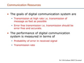
  • 10. Communication Resources • The goals of digital communication system are ▪ Transmission at high rate i.e. transmission of message as fast as possible ▪ Error free transmission i.e. transmission should be error free and accurate. • The performance of digital communication system is measured in terms of ▪ Probability of error in received signal ▪ Transmission rate Dr. S.M.Gulhane JDIET,Yavatmal
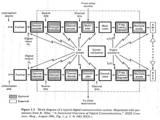
  • 11. Elements of Digital Communication
  • 12. Elements of Digital Communication • Information source • may either be analog or digital ▪ In digital comm. system it is the discrete information which is processed and transmitted. • Discrete information sources are characterized by ▪ Source alphabets: these are letters, characters, symbols or special character available from the information source. ▪ Symbol rate: rate at which the information source generate source alphabets. normally represented as symbols/ sec. ▪ Source alphabets probabilities: The rate of occurrence of each source alphabet is different and hence the prob. of occurrence of each source alphabets become one of most important property ▪ Entropy of the source sequence: the average information content per symbol in a long message. It is denoted by H & unit is bits per symbol. ▪ Source information rate: It is defined as the product of the source entropy & symbol rate & has the unit of bits per second. It is denoted by R.
  • 13. Elements of Digital Communication • Source encoder/decoder ▪ The function of source encoder is to efficiently represent the discrete source (using the minimum possible number of bits) ▪ The source encoder encodes the source information into a digital format for transmission ▪ The source encoder converts the symbol sequence into a binary sequence by assigning code words to the symbol in the input sequence. ▪ Codeword assigned may be o Fixed or Variable • The Source encoder is characterized by ▪ Codeword length: it is the no. of bits used to represent each codeword ▪ Block size: it is the maximum number of distinct codeword that the encoder can represent. ▪ Average data rate: it is the average data rate available from the encoder. ▪ Efficiency of encoder: it is the actual o/p data rate compare to the maximum achievable rate R.
  • 14. Elements of Digital Communication • Source encoder/decoder ▪ At the receiver the decoder converts the Binary o/p of the channel into a symbol sequence • Source encoder are vital in determining the transmitted bit rate and the quality of the recovered information • The quality and transmission rate are two factors that directly conflict each other. • The lower is the bit rate the more is the signal quality and vice versa. Dr. S.M.Gulhane JDIET,Yavatmal
  • 15. Elements of Digital Communication • Channel encoder/decoder ▪ The channel encoder enables the receiver to correct error that occur during transmission. ▪ To do so channel encoder add some redundant bit to the input bit sequence. ▪ This extra bits carry no information but they are used by the decoder in the receiver to detect and correct the error in the signal received. ▪ Addition of extra bit by the channel coding increases the bit rate hence required more bandwidth for transmission. However it allows the receiver to perform error detection and correction. ▪ Two methods o Block coding o Convolutional coding • The Channel encoder is characterized by ▪ Methods of coding used ▪ Rate or efficiency of the coder ▪ Error control capabilities ▪ Complexity of the encoder Dr. S.M.Gulhane JDIET,Yavatmal
  • 16. Elements of Digital Communication • Modulator and demodulator ▪ The process of modulation convert the channel coded signal into the format suitable for transmission over a communication channel. ▪ The signal of binary bits from the channel coder is given to the digital modulator which maps input binary sequence of 1’s and 0’s to the analog in order o to match the freq. spectrum o to minimize the effect of channel noise o to provide the capability to multiplex many signals o to overcome equipment limitation Dr. S.M.Gulhane JDIET,Yavatmal
  • 18. Line Coding • The communication Process how to represent digital data by using digital signals.? • There are numerous ways we can convert a string of logical 1’s and 0’s to a sequence of pulses. • Line coding involves converting a sequence of 1s and 0s to a sequence of pulses suitable for transmission over a channel. ADC Analog message 1 0 1 1 0 1... ? 1 0 1 1 0 1 OR 1 1 1 1 0 0
  • 19. Line Coding • There are various ways of Line coding suitable for ▪ Different channel characteristics ▪ Different applications and ▪ Performance requirements. Each line code has its own distinct properties • The most desirable features that are considered while choosing line codes are • Zero DC content • Enough Timing Content • Small Bandwidth • Small probability of error • Good power efficiency • Transparency • Built-in error detection Dr. S.M.Gulhane JDIET,Yavatmal
  • 20. Desirable features of Line coding • DC Content ▪ Signal obtained at the output of line coder may have dc component in it ▪ DC levels are inherently wasteful of power. ▪ If a signal is to pass through an ac coupled lines (or ac coupling in the transformers and repeaters) that does not allow the passage of a dc component, the signal is distorted and may create errors in the output. ▪ It is desirable to have zero dc in the waveform produced by a given line code • Bandwidth • We need small BW in order to be able to send more signals in a communication channel. • Different encoding of data leads to different spectrum of the signal. • The power spectrum and bandwidth of the transmitted signal should be matched with the spectrum of the channel to avoid distortion. • The transmission bandwidth needs to be sufficiently small compared to the channel bandwidth so that inter-symbol interference will not be a problem. .
  • 21. Desirable features of Line coding • Timing Content ▪ The waveform produced by a given line code should contain enough timing information so that the receiver can extract the clock information and decode the received signal properly. ▪ The timing content should be independent of source characteristics ▪ A long string of 1s or 0s may result in loss of timing at the receiver. • Built-in error detection ▪ It is desirable for the line coder to have error detection capability. • Transparency ▪ It should be possible to transmit every signal sequence correctly regardless of the patterns of 1s and 0s. • Probability of error ▪ The average error probability should be as small as possible. ▪ The lower probability of error makes the line code more reliable. • In addition complexity and economy are the determining factors for the choice of line coder.
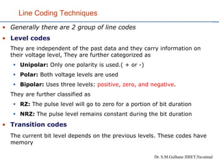
  • 22. Line Coding Techniques • Generally there are 2 group of line codes • Level codes They are independent of the past data and they carry information on their voltage level, They are further categorized as ▪ Unipolar: Only one polarity is used.( + or -) ▪ Polar: Both voltage levels are used ▪ Bipolar: Uses three levels: positive, zero, and negative. They are further classified as ▪ RZ: The pulse level will go to zero for a portion of bit duration ▪ NRZ: The pulse level remains constant during the bit duration • Transition codes The current bit level depends on the previous levels. These codes have memory Dr. S.M.Gulhane JDIET,Yavatmal
  • 23. Line Coding Techniques Dr. S.M.Gulhane JDIET,Yavatmal Level Coding Transition Coding Bi-phase Coding BNZS HDBn CMI Miller (DM)
  • 24. Unipolar NRZ • In unipolar encoding, only one polarity of voltage level is used • a binary ‘1’ is represented by positive voltage level and a binary ‘0 is represented by zero voltage. • 0 1 0 0 1 1 1 0 0 0 0 Unipolar NRZ The power spectral density for a unipolar NRZ signal with pulse duration of Tb is Dr. S.M.Gulhane JDIET,Yavatmal
  • 26. Unipolar NRZ The power spectral density contain a delta function at dc. Advantages • Relatively easy to generate the signal (TTL/CMOS) from a single power supply • Relatively low bandwidth of R Hz. Drawback • A dc component is always present corresponding to a waste of transmission power. • It has a large power spectral density near dc. • Poor clock recovery: A long stream of 0s or 1s will cause a loss of clock signal. • Has no error detection capability • Poor error rate performance • This line code is mostly used in magnetic tape recording. Dr. S.M.Gulhane JDIET,Yavatmal
  • 27. Unipolar RZ • In this line code, a binary ‘1’ is represented by nonzero voltage level for half of the bit period and a zero voltage level for rest of the bit duration. A binary ‘0 is represented by zero voltage level for the entire bit duration. Unipolar RZ The power spectral density for a unipolar RZ signal with a pulse duration of Tb/2 is Dr. S.M.Gulhane JDIET,Yavatmal
  • 28. Unipolar RZ Dr. S.M.Gulhane JDIET,Yavatmal
  • 29. Unipolar RZ Advantages • Ease of generation, requires only one power supply • Good clock recovery - periodic impulses at f = n/Tb can be used for clock recovery. Drawback • The first null bandwidth is 2R Hz. So the bandwidth requirement is higher than NRZ • Content significant dc component • The spectrum is not negligible near dc • Has no error detection capability • Poor error rate performance This code is mostly used in baseband data transmission and magnetic tape recording Dr. S.M.Gulhane JDIET,Yavatmal
  • 30. Polar NRZ • Polar encoding uses two voltage levels (positive and negative). • Encoding rule: ▪ A binary 1 is represented by a positive voltage +V and a binary 0 is represented by the negative voltage –V over the full bit period. ▪ Alternately, a 1 is represented by a -V and a binary 0 is represented by +V, without changing the spectral characteristics and performance. 1 0 1 1 0 0 0 0 1 0 1 Polar NRZ
  • 31. Polar NRZ • The power spectral density for a polar NRZ signal with a pulse duration of Tb is
  • 32. Polar NRZ • Advantages ▪ Low bandwidth R Hz ▪ Relatively easy to generate the signal but requires dual supply voltages. ▪ Bit error probability performance is superior to other line encoding schemes. • Disadvantages ▪ No error detection capability ▪ It has a large power spectral density near dc. ▪ Poor clock recovery: A long string of 1s and 0s will cause a loss of clock signal. ▪ Two power supplies required
  • 33. Polar RZ • A 1 bit is represented by positive-to-zero and a 0 bit by negative-to-zero. 1 0 1 1 0 0 0 0 1 0 1 • Advantage: ▪ Ensure synchronization since there is a signal change for each bit. The receiver can use these changes to build up, update and synchronize its clock. ▪ No dc component • The main disadvantage of RZ is that it requires two signal changes to encode one bit and therefore occupies more bandwidth. Polar RZ
  • 34. Bipolar Encoding • Bipolar encoding uses three levels: positive, zero, and negative. • In bipolar encoding the 1’s are represented by alternating positive and negative voltages the binary 0s are represented by zero level. • This line coding is often called as Alternate Mark Inversion (AMI) since 1’s (marks) are represented by alternating positive and negative pulses. The word mark comes from telegraphy and it means 1. • This code is also referred as pseudoternary since three different levels are used.
  • 35. Bipolar Encoding • Bipolar encoding uses three levels: positive, zero, and negative. • In bipolar encoding the 1’s are represented by alternating positive and negative voltages the binary 0s are represented by zero level. • This line coding is often called as Alternate Mark Inversion (AMI) since 1’s (marks) are represented by alternating positive and negative pulses. The word mark comes from telegraphy and it means 1. • This code is also referred as pseudoternary since three different levels are used.
  • 37. Bipolar Encoding • Advantages ▪ Has no dc component ▪ capable of recovering clock information - the clock signal can be easily extracted by converting the bipolar RZ signal to a unipolar RZ signal using full-wave rectification. ▪ capable of single error detection since a single error will cause a violation (the reception of 2 or more consecutive 1s with the same polarity) ▪ Low bandwidth requirements R Hz ▪ good error probability • Disadvantages ▪ A long string of zeros could result in loss of clock signal ▪ it needs twice much power as unipolar ▪ Two power supplies are required for generation ▪ The receiver has to distinguish between 3 logic levels AMI code is well known for its use in telephony. This code has memory. It is type of transition code.
  • 38. Biphase (Split-phase, Twined-Binary) Coding • In this coding pulses with 00 and 1800 phase are used ▪ Manchester and differential Manchester Coding are the two common Bi-phase techniques • Encoding rule for Manchester coding: ▪ A binary 1 is represented by a pulse that has positive voltage for first half of the bit duration and negative voltage for second half of the bit duration. ▪ A binary 0 is represented by a pulse that has negative voltage for first half of the bit duration and positive voltage for second half of the bit duration. • In this line code transitions occur at the middle of each bit. A high to low transition represents a 1 and a low to high transition represents a 0 or vice versa. • 1 is represented by--> • 0 is represented by--> Bit length
  • 39. Manchester Coding 1 0 1 1 0 0 0 0 1 0 1 The power spectral density for a Manchester signal with pulse duration of Tb/2 is
  • 40. Manchester Coding • Advantages: ▪ Zero DC because of half positive/half negative pulses ▪ Transparent: string of 1’s and 0’s will not affect DC levels ▪ Mid bit transitions are always present making it easy to extract timing information ▪ Bit changes at the Middle (mid bit Transition) serves as a clocking mechanism. ▪ Has good error rate performance • Disadvantage ▪ Require larger Bandwidth ▪ Has no error detection capability • It is well known for use in Ethernet Dr. S.M.Gulhane JDIET,Yavatmal
  • 41. Differential Manchester Encoding • Encoding Rule: ▪ Use Bi-phase coding ▪ 0 represented by no transition ▪ 1 represented by transition This results in presence or absence of transition at the beginning of the bit • In differential Manchester encoding, the presence (0) or absence (1) of transition at the beginning of the interval is used to identify the bit. • The transition at the middle of the bit is used only for synchronization. • The bit representation is defined by the inversion or non- inversion at the beginning of the bit.
  • 43. BNZS (Binary N Zero Substitution) Code • Bipolar code AMI has many desirable properties, but its major limitation is that a long stream of zeros can lead to loss of clock signal and timing jitter. • BNZS attempts to improve AMI by substituting a special code of length N for strings of N zeros. • This special code look like binary 1s but purposely produce violations of the AMI pulse convention. • The special code is chosen such that the desirable properties of AMI is retained. • The special code contain pulses facilitating synchronization even when long string of zeros occurs. • Three commonly used BNZS codes in telephony are B3ZS, B6ZS and B8ZS Dr. S.M.Gulhane JDIET,Yavatmal
  • 44. HDBn (High Density Binary) • High density binary n line code is just like BNZS with the following modification: • A string of N+1 consecutive zeros are replaced by a special code of length N+1 containing AMI violation. • Most commonly used HDBn code is HDB3 where a string of 4 zeros is replaced by a special code • A string of 4 zeros is replaced by either 000V or 100V. V is a binary 1 with the sign chosen to violate the AMI rule. This will let the receiver to know about the substitution. • corresponding HDB3 coding for sequence 10110000101. V 1 0 1 1 0 0 0 0 1 0 1 Must alternate in polarity
  • 45. HDBn (High Density Binary) • B00V is used when there are an even number of ones following the last special sequence and 000V is used when there are an odd number of ones following the last special sequence. ▪ where V’s are bipolar violation and B’s are valid bipolar signals. • Consecutive V pulses alternate in sign to avoid dc wander. • Because violation just happens at the fourth bit of the special code , it can be easily detected and will be replaced by a zero at the receiver. • It is also capable of error detecting because a sign error would make the number of bipolar pulses between violations even instead of odd. Dr. S.M.Gulhane JDIET,Yavatmal
  • 46. HDBn (High Density Binary) Dr. S.M.Gulhane JDIET,Yavatmal
  • 47. Coded Mark Inversion(CMI) • CMI is a modified polar NRZ code. Pulses corresponding to 1’s are encoded as an NRZ pulse with alternate polarity +V or –V and binary 0’s are encoded with midbit transition. • Spectrum is similar to bipolar-NRZ but has a clock component at the pulse rate • Has no dc component 1 0 1 1 0 0 0 0 1 0 1
  • 48. • A ‘1’ is represented by a transition at the middle of the bit and a ‘0’ is represented by no transition unless it is followed by another zero. • In this case another transition will occur at the end of the bit duration between 2 ‘0s’. 1 0 1 1 0 0 0 1 1 1 0 Miller code (DM)
  • 49. Miller code (Delay Modulation) • Advantages ▪ Has no dc component ▪ Majority of signal energy lies in frequencies less than 0.5R. ▪ Low bandwidth requirements R Hz ▪ good timing information recovery. The clock frequency is embedded in the code for all symbol sequences ▪ good error probability • Disadvantages ▪ not capable of error detecting ▪ Small spectrum at dc may not be acceptable for some transmission channels Attractive for magnetic recording and PSK signaling Dr. S.M.Gulhane JDIET,Yavatmal
  • 51. Line coding review In general, there is no optimum waveform choice for all digital transmission systems. • Return-to-zero (RZ) waveforms may be attractive when the bandwidth is available. Because RZ waveforms always have two level transitions per symbol interval, symbol timing recovery can easily be achieved. • For bandwidth-efficient systems, non-return-to- zero (NRZ) waveforms are more attractive. However, long strings of ones or zeros should be avoided to allow accurate recovery of symbol timing. • Polar or unipolar signals are found in most digital circuits, but they may have a nonzero dc level. • Bipolar and Manchester signals will always have a zero dc level regardless of the data sequence. Dr. S.M.Gulhane JDIET,Yavatmal
  • 53. Scrambling • Scrambler may be used as a data randomizer or for encryption • As a randomizer, it makes the data more random by removing long strings of 1’s or 0’s. thus helpful in timing extraction. • As an encryption, scramblers may be used for preventing unauthorized access to the data • The simplest form of scrambling is to add a long PN sequence to the data sequence (via modulo 2 addition). • A scrambler consist of a feedback register. A corresponding descrambler has a feed forward register • In receiver, descrambling is done using the same PN sequence. • A scrambler/descrambler is defined by the polynomial of its LFSR and its initial state. Dr. S.M.Gulhane JDIET,Yavatmal
  • 54. Polynomial is 1+x2+x5 T = S  FT = S  D2T  D5T R= T  FT = S  FT  FT = S In scrambler T is operated by F and added to S F- stands for operator, where F= D2  D5 - D denotes the effect of delaying sequence by one - DkT - represents sequence T delayed by k bits RT’TS Dr. S.M.Gulhane JDIET,Yavatmal Scrambling
  • 55. Scrambling Example • Exercise: 100000000000 • Scrambler • Descrambler S T S T S’T’S’ T’ initial state
  • 56. Scrambling Example • Realize the scrambler and descrambler with a PN Sequence LSFR polynomial 1+x3+x5 and determine the sequence obtained at the output of scrambler and descrambler for the input sequence 11010 • Descrambler S’ 1 1 0 0 1 5 3 4 2 1 + + TS 0 0 0 0 0 1 0 0 0 1 1 0 0 0 0 0 1 1 0 0 1 1 0 0 0 1 1 0 0 1 0 1 0 1 1 initial state 5 3 4 2 1 T 0 0 0 0 0 1 0 0 0 1 1 0 0 0 0 0 1 1 0 0 1 1 0 1 0 1 1 0 1 0 1 0 0 1 1 1 1 0 1 0 Dr. S.M.Gulhane JDIET,Yavatmal
  • 57. Scrambling Example • Realize the scrambler and descrambler with a PN Sequence LSFR polynomial 1+x3+x5 and determine the sequence obtained at the output of scrambler and descrambler for the input sequence 11010 S’ 0 1 0 1 0 5 3 4 2 1 + + TS 0 0 0 0 0 0 0 0 0 0 1 0 0 0 0 0 0 1 0 0 0 1 0 1 0 0 1 0 1 0 1 1 0 1 0 initial state 5 3 4 2 1 T 0 0 0 0 0 1 0 0 0 0 1 0 0 0 0 0 0 1 0 0 0 1 0 1 0 0 1 0 1 0 0 1 0 1 0 0 1 0 1 1 Scrambler Descrambler Thus the sequence is 11011