SlideShare a Scribd company logo
Software
Engineering
V1.8
Nov 2024
Agenda
• Software Engineering Overview
• Software Methodologies
• Software Project Management Concepts
– Software Process and Project Metrics
– Software Project Estimation
– Risk Management
• Software Requirements Analysis
• Software Design
• Software Testing
• Software Quality Assurance
• Software Configuration Management
2
Software Engineering
Software
4
Software
• Instructions (Computer Programs) that when executed provide desired features,
function and performance
What is a Project?
5
What is a Project?
• A project is defined as a “temporary endeavour with a beginning and an end and it
must be used to create a unique product, service or result”
• End results have specific goals – Time, Cost, Performance & Quality
Software Characteristics
6
• Software is a logical rather than a physical system element
• Software doesn’t wear-out
• Software is not susceptible to the environment maladies
• Software however deteriorates with time mainly due to change
• Software failure rate is high at the beginning but tapers out due to defect fixing
V/S
• Hardware wears out with time due to the effects of environment (dust, vibration, temp….)
• Hardware failure rate shows a bathtub curve
• Hardware failure can be corrected by spare part replacement
Software Application Domains
7
• System Software – A collection of programs written to serve other programs (compilers, editors,
Operating system components, drivers, networking software…..)
• Application Software – Stand alone programs that solve a specific business need
• Engineering/scientific Software – number crunching programs, astronomy, CAD, Meteorology)
• Embedded Software – Resides within a product or system (Automobile, Medical Equipment, Industrial
Automation……)
• Web/Mobile Applications – Browser based apps and mobile devices
• Artificial Intelligence Software – Applications include Robotics, Expert Systems, Artificial neural
networks, gaming
Changing Nature of Software
8
• WebApps – Sophisticated computing tools that not only provide stand alone function to the end
user but have now integrated with corporate databases and business applications
• Mobile Applications – Specifically designed to reside on a mobile platform (IOS, Android) with
persistent storage capabilities within the platform
• Cloud Computing – Encompasses an infrastructure or ecosystem that enables any user, anywhere,
to use a computing device to share computing resources on a broad scale
• Product Line Software – A set of software –intensive systems that share a common managed set of
features satisfying the specific needs of a particular market segment
Software Engineering
9
Software Engineering:
• Software engineering is the application of a systematic, disciplined, quantifiable
approach to the development, operation, and maintenance of software
• Software Engineering is the establishment and use of sound engineering
principles in order to obtain economically software that is reliable and works
efficiently on real machines
Software Engineering – A layered Technology
10
➢ Software Engineering rests on a commitment to Quality
➢ Process Layer is the foundation
➢ Engineering methods provide the “how to’s”
➢ Tools provide automated or semi automated support for the process and the methods
A Quality Focus
Process
Methods
Tools
Software Engineering Process
11
• The Software Process:
• A collection of activities , actions , and tasks that are performed when some work product is to be
created with a broad objective
• Is applied irrespective of the application domain, size, complexity, efforts
• Not a rigid prescription but an adaptable approach
• The Process Framework:
• Communication – Process of understanding Customer requirements, needs, pain areas
• Planning – A map that guides the team – Project Plan
• Modeling – The design of how to implement the requirements
• Construction –Execution or building the product
• Deployment – Delivery to the Customer
Process Framework – Umbrella Activities
12
• Monitoring and Control – Allows the team to assess progress against plan and take corrective
actions wherever required
• Risk Management – Assess risks that may affect the outcome of the project
• Quality Assurance – Define and conduct activities to ensure quality
• Technical reviews – Assess engineering work products to uncover and remove errors
• Measurement – Defines and collects process, project, and product measures that assists the team
to deliver software that meets stakeholders needs
• Software Configuration Management – Manages the effects of change throughout the life cycle
• Reusability Management – Defines criteria for work product reuse
• Work product preparation and production – Encompasses the activities required to creat work
products such as models, documents, logs, forms and lists
Software Engineering Practice
13
• Understand the problem:
• Who are the stakeholders?
• What are the unknowns? What data functions and features are required to solve the problem
• Can the problem be compartmentalized? Is it possible to represent smaller problems that may
be easier to understand?
• Can the problem be represented graphically? Can an analysis model be created?
• Plan the Solution:
• Have you seen similar problems before? Have we done a similar project before?
• Has a similar problem been solved? If so, are elements of the solution reusable?
• Can subproblems be defined?
• Can you represent a solution in a manner that leads to effective implementation? Can a design
model be created?
Software Engineering Practice
14
• Carry out the Plan:
• Does the solution conform to the plan? Is source code traceable to the design model?
• Is each component part of the solution provable correct? Has the design code been reviewed?
• Examine the Result:
• Is it possible to test each component part of the solution? Has a reasonable testing strategy
been implemented?
• Does the solution produce results that conform to the data, functions, and features that are
required?
The overall approach is commonsense. In fact, it is reasonable to state that a commonsense
approach to software engineering will never lead you astray!
General Principles
15
• The reason it all exists – To provide value to users – To address a pain area
• Keep it Simple Stupid (KISS) – All design should be as simple as possible. The payoff is software that
is more maintainable and less error-prone
• Maintain the Vision – A clear vision is essential to the success of a software project
• What you produce others will consume – Always specify design, and implement knowing someone
else will have to understand what you are doing. Specify with an eye to the users
• Be open to the future – A system with a long lifetime will add more value. Easy to adapt to change
• Plan ahead for Reuse – Reuse saves time and effort. Planning ahead for reuse reduces cost and
increases the value
• Think – Placing clear complete thought before action almost always produces better results
Software Development Myths
16
Management Myths:
• We already have a book of standards and procedures……Is it being used?
• If we get behind schedule, we can add more programmers and catch up……Adding people to a late software
makes it later (Brooks)
• If we decide to outsource the software project to a third party, I can relax……If we cannot understand how to
manage and control projects internally, outsourcing will not help
Customer Myths:
• A general statement of objectives is sufficient to begin writing programs – we can fill in the details later……An
ambiguous statement of objectives is a recipe for disaster
• Software requirements continually change, but change can be easily accommodated because software is
flexible……Impact of change varies with time. Later the changes in the life cycle, the more it costs
Practitioner’s Myths:
• Once we write a program and get it to work, our job is done……The sooner you will begin writing code, the longer
it will take
• Until I get the program running, I have no way of assessing its quality……Software reviews are one of the most
effective ways for assessing the quality
• The only deliverable work product for a successful project is the working program……A working program is only
one part of a software configuration. A variety of work products such as models, documents, plans are included
• Software Engineering will make us create voluminous and unnecessary documentation and will slow us
down……Software Engineering is not about creating documents. It is about creating a quality product. Better
quality leads to reduced rework and thereby faster delivery times
Software Process Structure
17
Software Process:
Process Framework:
Umbrella Activities:
Framework Activity # 1:
Software engineering action # 1.1
Tasks Sets
Work Tasks
Work Products
Quality Assurance points
Project Milestones
Software engineering action # 1.k
Tasks Sets Work Tasks
Work Products
Quality Assurance points
Project Milestones
Framework Activity # n:
Software engineering action # n.1
Tasks Sets Work Tasks
Work Products
Quality Assurance points
Project Milestones
Software engineering action # n.m
Tasks Sets
Work Tasks
Work Products
Quality Assurance points
Project Milestones
Software Process Flows
18
Communication Planning Modeling Construction Deployment
Linear Process Flow:
Iterative Process Flow:
Communication Planning Modeling Construction Deployment
Software Process Flows
19
Evolutionary Process Flow:
Parallel Process Flow:
Communication
Planning Modeling
Construction
Deployment
Communication Planning
Modeling
Construction Deployment
Increment Released:
Software Process Models
20
• The word ‘Process’ emphasizes the idea of a system in action. In order to achieve an
outcome, the system will have to execute one or more activities: This is its process
• These activities can be organized in different ways – ‘Process Models’
•A classical Model also known as one-shot or once-through model
•A sequence of activities working from Top to Bottom
•Best suited where the Requirements are well defined & development methods well
understood
Waterfall
•A Feasibility Study is carried out at the beginning of the project
•Greater level of detail is considered at every stage of the project
•Portrayed as a loop or a Spiral where the system to be developed is considered in more
detail in every step
Spiral
•The approach is more incremental and iterative
•Also called as Dynamic Systems Development Method
•8 Core principles: Focus on Business Need, OTD, Collaborate with user, Quality, Iterative
Development, Incremental Build, Communicate & Control
Atern/DSDM
•Also referred to as Rapid Prototyping Model
•The major aim is to reduce costs and cycle time and improved Change Management
•Increased Customer involvement as feedback is sought on successive developed
prototypes which are refined
RAD
•Designed to overcome important disadvantages of the Traditional Methodologies
•The approach involves development of one feature at a time and released to the
Customer for their use and feedback
•Includes various sub methods: Scrum, XP, Kanban
Agile
Waterfall
21
Concept
Design
Develop
Test
Deliver
Waterfall
Requirements
Analysis
Architectural
Design
Component
Design
Code
Design
Acceptance
Testing
System
Testing
Integration
Testing
Unit
Testing
Executable Software
Incremental Process
22
Incremental Process Model
Project Calendar Time
Software
Functionality
and
Features
Communication
Planning
Modeling (Analysis,
Design)
Construction (Code,
Test)
Deployment
(Delivery, Feedback)
Increment # 1
Delivery of 1st Increment
Increment # 2
Delivery of 2nd Increment
Increment # n
Delivery of nth Increment
Quick Plan
Modeling Quick
Design
Construction of
Prototype
Deployment
Delivery &
Feedback
Communication
Evolutionary Process Models
23
Prototyping
• Best suited when the Customer defines a set of general objectives but does not identify detailed requirements for
functions and features
• The developer may be unsure of the efficiency of an algorithm, the adaptability of an operating system or the
form that human-machine interaction should take place
Spiral Model – Different Phases
24
• An evolutionary software process that couples the iterative nature of prototyping with the controlled and
systematic aspects of Waterfall model
• The software is developed in a series of evolutionary releases. Early iterations release might be a prototype and
later iterations would be more complete versions of the system
The Unified Process
25
Inception
Elaboration
Construction
Transition
Production
•Encompasses both Customer communication & Planning activities
•Business requirements (Use Cases) are identified and a rough architecture is proposed
•A plan for the iterative, incremental nature of the project is developed
•Use cases that were developed as part of the inception phase are refined and expanded
•Expands the architecture to include Use Case Model, Analysis Model, Design Model, Implementation
Model, and Deployment Model
•A first cut executable system representation is done
•Using the architectural model as input, the construction phase develops or acquires the components to
make the Use case operational
•Analysis and design models are completed to reflect the final version of the software increment
•All necessary and required functions and features are implemented
•Unit tests are designed and executed and integration activities are conducted
•Encompasses the delivery and feedback activity
•Software is given to end users for beta testing for defects and feedback
•The team creates the necessary support information (User manuals, troubleshooting guides, and
installation procedures
•Ongoing use of the software is monitored
•Support for the operating environment (infrastructure)is provided
•Defect reports and requests for changes are submitted and evaluated
Agile Development
What is Agility?
• Software development today is driven by change. The pervasiveness of change is the primary driver for Agility
• Agility is more than an effective response to change
• It encourages team structures and attitudes that make communication between stakeholders more facile
• It emphasizes rapid delivery of operational software
Agility and the cost of change
• The cost of change increases nonlinearly as the project progresses
• It is easy to accommodate a change during the upper life cycle especially requirements phase
• Changes later in the life cycle require changes across the phases (Requirements, Design, Coding, Testing)
• A well defined Agile process flattens the cost of change curve
Development Schedule progress
Development
Costs
Cost of change using conventional software processes
Cost of change using Agile processes
Idealized Cost of change using Agile processes
Agile Process
27
Key Assumptions
• It is difficult to predict in advance which software requirements will persists and which will change
• It is difficult to predict how Customer priorities will change as the project proceeds
• For many types of software, the design and construction are interleaved. Both activities should be
performed in tandem so that the design models are proven as they are created
• Analysis, Design, Construction, and Testing are not as predictable (from a planning point of view) as
we might like
How do we create a process that can manage unpredictability?
• An incremental development strategy should be instituted!
• Adaptation keeps pace with change (unpredictability)
• This iterative approach enables the Customer to evaluate the software increments
regularly, provide necessary feedback to the development team, and influence the process
adaptations that are made to accommodate the feedback
Agile Principles
28
1. Highest priority is to satisfy the Customer through early and continuous delivery of valuable
software
2. Welcome changing requirements even late in development. Agile processes harness change for the
Customers competitive advantage
3. Deliver working software frequently, from a couple of weeks to a couple of months with a
preference to the shorter time scale
4. Business people and developers must work together daily throughout the project
5. Build projects around motivated individuals, Give them the environment and support they need,
and trust them to get the job done
6. The most efficient and effective method of conveying information to and within a development
team is face-to-face conversation
7. Working software is the primary measure of progress
8. Agile processes promote sustainable development. The sponsors, developers, and users should be
able to maintain a constant pace indefinitely
9. Continuous attention to technical excellence and good design enhances agility
10. Simplicity – the art of maximizing the amount of work done – is essential
11. The best architecture, requirements, and design emerge from self organizing teams
12. At regular intervals the team reflects on how to become more effective, then tunes and adjusts its
behavior accordingly
Agile – Extreme Programing
29
XP Process:
Release – Software increment
Refactoring
User Stories
Values
Acceptance test criteria
Iteration plan
Simple Design
CRC Cards
Spike solutions
Prototypes
Pair programming
Unit test
Acceptance testing
Continuous integration
Agile Scrum Model
30
Develop Develop
Test Reiterate
Design Design
1. The Project is divided into sprints of 2 to 4 weeks where incremental functionality is completed and delivered
2. Key Role holders – Product Owner, Scrum Master, Team Member
3. Key Artefacts – Product Backlog, Sprint Backlog, Sprint Burn Down and Burn Up Charts
4. Scrum Ceremonies – Sprint Planning, Daily Scrum, Sprint Review Meeting
Agile – Scrum
31
Product Backlog
Initiate
Project
P
o
t
e
n
t
i
a
l
P
r
o
j
e
c
t
s
Highest Priority
User Stories
Sprint Backlog
Initial Funding
Initial Architectural
Vision
Release into
Production
Operate and
Support in
Production
Funding &
Feedback
Enhancement
Requests and
Defect Reports
Daily Scrum:
Daily standup meetings
to Share status and
potential issues
2-4 weeks Sprint
• Brainstorm
• What went well
• What went wrong
• Time-boxed issue identification
• Vote / Team Temperature
• Discuss action items
• Follow-up
Sprint Execution:
-Test Driven Development
-Continuous Build & Integration
-Test script Generation
-Automated Testing
Sprint Review Meeting: -
Demo for stakeholders
-Gain approval for next iteration
Sprint Retrospective
Meeting- learn from
experience
Sprint Planning Meeting:
-select work items for the iteration
- Effort estimation and
identification of work items
Release Planning Meeting
= 1 User Story
Legend
Product Owner
Scrum Master
Stakeholders
Scrum Team
Rather than doing all of one thing at a time...
…Scrum teams do a little of everything all the time
Agile – Dynamic Systems Development Method
32
• Provides a framework for building and maintaining systems through the use of incremental prototyping in a
controlled environment
• An iterative software process in which each iteration follows the 80% rule. Only enough work is required for each
increment to facilitate movement to the next increment
Functional
Model iteration
Design and Build
Iteration
Implementation
•Produces a set of incremental prototypes that demonstrate functionality to the Customer
•All DSDM prototypes are intended to evolve into deliverable applications
•Intent is to gather additional requirements through feedback from users as they exercise
the prototype
•Revisit and review prototypes that were built during the functional model iteration
•In some cases the functional model iteration and the design and build iteration occur
concurrently
•Places the latest software increment (An operational prototype) into the operational
environment
•The increment may be 100% complete or changes may be requested as the increment is put
into place
Agile Unified Process
33
• AUP adopts a “serial in the large” and “iterative in the small” philosophy for building computer based systems
• By adopting the classic UP phased activities (Inception, Elaboration, Construction, and Transition) – AUP provides a serial overlay
(linear sequence of software engineering activities)
Modeling
Imlementation
Testing
•UML representations of the business and problem domains are created
•These models should be just barely good enough to allow the team to proceed
•Models are translated into source code
•Delivery of software increment and acquisition of feedback from the end users
Each AUP iteration addresses the following activities:
•Like XP, the team designs and executes a series of tests to uncover defects
Deployment
•Configuration management addresses change management, Risk Management and control
of any persistent work products
•Project Management tracks and controls the progress of the team and coordinates team
activities
Configuration
and Project
Management
Agile Methods – Basic Principles
34
• Incremental Delivery after each time box
• Features are decomposed into small parts that can be incrementally developed
• Each incremental part is developed over an iteration
• The Time to develop an iteration is called a time box
• Face-to-Face communication
• Emphasis on Face-to-Face communication over written documents
• Daily contact through communication channels
• Customer Interactions
• Includes Customer representative in the team
• Customer participates in review meetings and provide feedback
• Minimal Documentation
• Documents are created on a need to know basis
• Documentation is light so easy to keep up-to-date and consistent
• Pair Programming
• In this approach two programmers work together at one station
• The programmers switch roles every hour or so
• Lesser defects are expected
Waterfall V/S Agile
35
Strengths Weaknesses Type of projects
Waterfall:
1. Simple projects
2. Clear Requirements
3. Past projects experience
4. Intuitive and logical
1. Requirements frozen early
2. Does not encourage changes
3. Cycle time is too long
4. Late user feedback
1. Projects with very clear
requirements
2. Short duration projects
3. Automation of existing manual
systems
Agile:
1. Regular deliveries
2. Reduces risks
3. Accommodates changes
4. Quick user feedback
5. Prioritizing requirements
1. Requirements spillover from
sprints
2. Backlog bloating
3. Possibility of rework and
defects
4. System architecture and
structure may suffer as
frequent changes are made
1. For projects where time is of
essence
2. Risk of long projects cannot be
taken
3. Requirements are not known
and will be known only with
time
Agile Methods – Sub Methods
36
• Based on Four Core Values: Communication and Feedback, Simplicity,
Responsibility, Courage
• Code is developed in iterations of 1 to 4 weeks during which specific features
are created. Pair programming is followed
• Small Releases – Time between Releases must be as short as possible
• Simple Design and Testing is done at the same time as coding using
automation tools
Extreme
Programming
(XP)
• The Project is divided into sprints of 2 to 4 weeks where incremental
functionality is completed and delivered
• Key Role holders – Product Owner, Scrum Master, Team Member
• Key Artefacts – Product Backlog, Sprint Backlog, Sprint Burn Down and Burn Up
Charts
• Scrum Ceremonies – Sprint Planning, Daily Scrum, Sprint Review Meeting
Scrum
• Main Objective is to provide visibility to the workflow. This is expected to
debottleneck congestions in the process and minimize delays
• Kanban Board and Kanban Card – Typically a white board on which Kanban
Cards are attached to represent the work items. A card is moved on the board
as the corresponding work is completed at a stage
• Visibility – It shows work assigned to each developer at any time and the work
flow. Bottlenecks get highlighted. Cycle time is tracked and optimized
Kanban
Agile Methods – Kanban Boards example
37
PROJECT MANAGEMENT
What is Project Management?
39
What is Project Management?
• Project Management involves the Planning, Monitoring, and control of the
People, Process and the Events that occur as project evolves from a preliminary
concept to an operational implementation
PSI21892
Project
Profitability
homepage_photo_okfingers
Customer
Satisfaction
newPDRIlogo
Quality Management &
Operational Focus
kmLessonsLearned
Knowledge
Management
team
People
Management
Project
Manager
Project Management & the 4 P’s
40
Effective Project Management focuses on the 4 Ps:
The People
• People must be organized into effective teams, motivated to do high quality
work
The Product
• The requirements / pain areas must be communicated from Customer to
developer, partitioned into logical parts, and positioned for work by the project
team
The Process
• A common framework with an appropriate process engineering paradigm to
come up with a set of tasks
The Project
• The project needs to be organized in a manner that enables the team to
succeed
PMI and Framework Overview
41
About PMI?
• The PMI was founded by Ned Engman (McDonnel Douglas Automation), James Snyder and Susan Gallagher
(SmithKline & French Laboratories), Eric Jenett (Brown & Root) and J Gordon Davis (Georgia Institute of
Technology) at the Georgia Institute of Technology in 1969 as a non-profit organization
PMI Objectives:
• Foster recognition of the need for professionalism in project management
• Provide a forum for the free exchange of project management problems, solutions and applications
• Coordinate industrial and academic research efforts
• Develop common terminology and techniques to improve communications
• Provide interface between users and suppliers of hardware and software systems
• Provide guidelines for instruction and career development in the field of project management
PMI Services:
• Development of standards, research, education, publication, networking-opportunities in local chapters,
hosting conferences and training seminars, and providing accreditation in project management
• PMI has recruited volunteers to create industry standards, such as "A Guide to the Project Management
Body of Knowledge", which has been recognized by the American National Standards Institute (ANSI). In
2012 ISO adapted the project management processes from the PMBOK Guide 4th edition
PMI India:
• PMI India office was established with the sole goal of advancing project management profession and
inculcating a project management culture within the establishments across government, academia, and
industry -- https://pmi.org.in
PMI Framework -- Key Knowledge Areas
42
PMI
Integration
Management
Scope
Management
Time
Management
Cost
Management
Quality
Management
Human
Resources
Management
Communication
Management
Risk
Management
Procurement
Management
Stakeholder
Management
Project Initiation
43
Project Life Cycle:
Components of Project Initiation:
• Project Charter
• Project Management Plan
Initiating Planning
Monitoring
&
Control
Executing
Closing
Project Initiation
44
Project Execution Approach:
• Need to establish a structured approach
• A disciplined and structured approach will ensure:
• Meet the needs of the stakeholders (Customer, Project Manager……)
• Measure performance against the strategic plan of the organization
Steps involved:
• Define Project Scope
• Establishing project priorities
• Creating the WBS
• Integrating the WBS with the Organization
Defining Project Scope
45
Scope definition checklist:
• Project Objective
• Deliverables
• Milestones
• Technical Requirements
• Limits and Exclusions
• Reviews with Customer
Project Scope:
• Defining the project scope sets the stage for developing a project plan
• Project scope is a definition of the end result or mission of the project, a product or service
Establishing project priorities
46
Priority Matrix:
Consider a project for developing a new WiFi
Router:
• Time to Market is important to sales –
Time can be enhanced – reduce
completion time
• In doing so, project going over budget is
acceptable
• But original performance specifications
cannot be compromised
Project Priorities:
• Important to manage the trade-offs among
Time, Cost , and Performance
• Imperative to establish priorities
• Set up a priority Matrix
Time Performance Cost
Constrain
Enhance
Accept
Project Planning -- Estimation
47
What is Estimation?
Estimation is a process of forecasting or approximating the time and cost of completion of the project
Why Estimating Time and Cost are important?
• Estimates are needed to support good decisions
• Estimates are needed to schedule work
• Estimates are needed to determine how long a project should take and its cost
• Estimates are needed to determine whether the project is worth doing
• Estimates are needed to develop cash flow needs
• Estimates are needed to determine how well the project is progressing
Consider this:
• Inaccurate Estimates lead to false expectations and Customer dissatisfaction
• Accuracy is improved with greater efforts, but is it worth the time and costs? Estimating costs
money!
• Project Estimates become a trade-off balancing the benefits of better accuracy against the
costs for securing increased accuracy
• Cost, Time, and Budget estimates are the lifeline for control
Project Planning -- Estimation
48
Project Estimation is indeed a yardstick for
project cost control. If the yardstick is faulty,
you start on the “wrong Foot”
Do not Underestimate the Estimate!!
Estimation – Size by Function Points
49
Measurements Parameters Examples
1.Number of External Inputs(EI) Input screen and tables
2. Number of External Output (EO) Output screens and reports
3. Number of external inquiries (EQ) Prompts and interrupts.
4. Number of internal files (ILF) Databases and directories
5. Number of external interfaces (EIF) Shared databases and shared routines.
• Weighting Factors
• Unadjusted FP
• Complexity Adjustment Factor
FP = UFP * CAF
Planning by Use of Baselines
50
Projects Size (FP) Actual Efforts
(PDs)
Defects
Pr1 100 118 (0.84) 200
Pr2 150 183 (0.81) 330
Pr3 175 224 (0.78) 420
Pr4 200 267 (0.74) 540
Pr5 250 329 (0.75) 725
Pr6 500 602 (0.83) 1000
Pr7 750 1071 (0.70) 2250
Pr8 1000 1471 (0.67) 3200
Pr9 1500 2419 (0.62) 5250
Pr10 4000 7273 (0.54) 14400
Pr1 100/118 = 0.847 Pr7 750/1071 = 0.7
Pr2 150/183 = 0.819 Pr10 4000/7273 = 0.549
If the Size is 1200 FPs, How many PDs will I need?
Regression Equation
PDs = 1.559*FP – 28.85 = (1.559*1200 – 28.85)
= 1890 PDs
Size
Effort
.
.
.
.
. PDs = 1.559*FP – 28.85
Estimation – Size by Function Points
51
International Function Points Users Group IFPUG
Size = 1000 FPs
Productivity = Size / Efforts = FP / PD
0.7 FP in 1 PD of effort = 0.7/1 FP / PD Baselines (Historical Data)
Effort = Size / Productivity
= 1000 / 0.7
= 1428.57 = 1429 PDs (Efforts spread across the life cycle)
Planning by Use of Baselines
52
Size
0
5000
10000
Pr1 Pr2 Pr3 Pr4 Pr5 Pr6 Pr7 Pr8 Pr9
Pr10
100 150 175 200 250 500 750 1000 1500
4000
118 183 224 267 329 602 1071 1471 2419
7273
Pr1 Pr2 Pr3 Pr4 Pr5 Pr6 Pr7 Pr8 Pr9 Pr10
Size 100 150 175 200 250 500 750 1000 1500 4000
Actual Efforts 118 183 224 267 329 602 1071 1471 2419 7273
Productivity
Size Actual Efforts
Size
0
5000
10000
15000
Pr1 Pr2 Pr3 Pr4 Pr5 Pr6 Pr7 Pr8
Pr9
Pr10
100 150 175 200 250 500 750 1000 1500 4000
200 330 420 540 725 1000 2250 3200 5250
14400
Pr1 Pr2 Pr3 Pr4 Pr5 Pr6 Pr7 Pr8 Pr9 Pr10
Size 100 150 175 200 250 500 750 1000 1500 4000
Defects 200 330 420 540 725 1000 2250 3200 5250 14400
Defect Density
Size Defects
Estimation – Type of Costs & Refining
53
Cost Breakdown:
1. Direct Costs:
Cost of Labour, Material, Equipment, Others. These costs are clearly chargeable to a specific work
package
2. Direct Project Overhead Costs
Costs tied to project deliverables or work packages. Salaries….usually a ratio of the dollar value of
the resources
3. General & Administrative Overhead Costs:
These represent organization costs which are not directly linked to the project. These costs are
carried for the duration of the project. (Advertising, Accounting, Senior Management. Generally a
% of the total direct costs
Refining Estimates: Generally a % of adjustment is done over the original estimates
1. Interaction Costs: Time spent on interaction between departments for queries and issues
2. Normal conditions do not apply: Costs associated when project demonstrates variations from
normal assumed conditions
3. Things go wrong on the project: Design flaws, Extreme weather conditions, unplanned leaves……
4. Changes in Scope and plans: Major changes during execution and change management process
5. Overly optimistic: Tendency to overestimate completion of tasks and underestimate duration
6. Strategic misrepresentation: Underestimation of costs and overestimation of benefits in order to
win proposals
Work Breakdown Structure
54
What is a WBS?:
• A WBS is a deliverables oriented collection of project components
• It is a Categorization and Decomposition of the Project Scope Statement
• Breaking down the massive project scope statement into smaller more manageable components
Why do you need a WBS?:
• It serves as an input to 5 key Project Management Activities:
• Cost Estimate
• Resource Planning
• Risk Management Planning
• Activity Definition
• Defines the work required to be done
• Helps in working towards the deliverables – create, manage and control tasks
• Help prevent scope change
What is a Work Package?:
• A work package is the smallest element of the WBS
• A WBS element that you can schedule, estimate the costs, and monitor and control
Create a Milestone List
METRICS IN PROJECT MANAGEMENT
Key Areas …. Measurement & Metrics
56
• Measurement enables managers to improve the software process ; assist in the planning,
tracking, and control of a software project and access the quality of the product that is
developed
Process
Product
Technology
People
Customer
Characteristics
Business
Conditions
Development
Environment
Metrics
57
“If you don`t know where you are going, any road will do” –
CHINESE PROVERB
“ If you don`t know where you are, a map won`t help” WATTS S.
HUMPHREY
“What you cannot measure, you cannot manage-” DRUCKER
Introduction
58
• Why Measure?
• What to Measure?
• Designing a Metrics Program
Why Measure?
59
• Objectives of Measurements
✓ For Projects
• Proper Estimation & Planning
• Tracking progress against plan
• Get early warnings
• Take timely corrective actions
✓ For Organization
• Basis for setting benchmarks
• Basis for driving process improvements
• Tracking Process performance against Business Objectives
(PPM)
What to Measure?
60
Basic measures:
✓ Size (e.g., function points, source lines of code, classes,
features, etc.)
✓ Efforts (e.g., person days, etc.)
✓ Schedule (e.g., start date, end date, etc.)
✓ Defects (e.g., no. of defects – review & testing, no. of
post-delivery defect, etc.)
Example of Metrics:
✓ Variance (size, efforts & schedule related)
✓ Productivity (size / effort)
✓Test Case Adequacy, Test Case Effectiveness, Defect
Detection Index
Frequency of Metrics
61
• When is the metric generated?
✓End of task or milestone or
project
✓End of week or month
✓End of a Sprint
Metrics Report Analysis
Effort Variance (Actual) Schedule Variance
(Actual)
Effort Variance
(Predicted)
Schedule Variance
(Predicted)
10% 1% 25% 5%
Review Effectiveness Defect Density Defect Removal
Efficiency
Defect Age
50% 3 Defects / FP 87% >2
Test Case Adequacy Test Case Efficiency
100% 60%
Analysis:
1. More effort than planned – (Resources facing Technology issues, roadblocks → schedule slippage, High DD, Low DRE, Low RE,
Regression
2. Low RE → Understanding of the requirements, Review process is not streamlined, Skill of the reviewer
3. High DD → Low RE leading to more defects and also due to regression, Coding stds are not followed, Skill of the coder, Issues with
the development / implementation process
4. High defect leakage to the Customer, High defect age
5. Low TCE → Quality of Test cases, Complexity of the requirement, Skill of the tester
Corrective Action:
1. Revisit the SRS / design for new reviews through SMEs, Increase the review cycles
2. Train the resources in the technology being used
3. Review the development / deployment process
4. Use Best practices for Reviews, coding, replace the inefficient resources, peer reviews & testing
5. Optimise the process, remove unwanted process steps → Save valuable efforts
Agile -- Metrics
63
Burn Down Chart
Agile -- Metrics
64
Burn Up Chart
Agile -- Metrics
65
Velocity
Agile – Metrics & Challenges
66
What to measure?
Efforts (Cost), Schedule, Quality of Deliverables, Customer Satisfaction
Traditional Methodology:
Measurements done at phase level
➢ Size : Function Points, LOC, Use-case Points
➢ Efforts / Cost – Effort Variance / Cost Variance
➢ Schedule – Schedule Variance
➢ Quality –
➢ Defect Density, Review Effectiveness, Defect
Removal Efficiency
➢ Efficiency, Test Case Effectiveness
➢ Defect Density – Defects / FP, Defects / KLoc
➢ Defect Age, Defect Acceptance Rate
➢ Critical Chain Concept can be used for effective Buffer
Management
➢ Earned Value can be used for prediction / Forecasts to
facilitate Proactive Project Management
➢ Customer Satisfaction – Customer Satisfaction Survey /
Feedback
Agile Methodology:
Measurements done at Sprint and Iteration level
➢ Size : Story Points
➢ Efforts / Cost – Effort Variance / Cost Variance
➢ Schedule – Schedule Variance
➢ Quality –
➢ Defect Density – Defects/Story Point, Review
Effectiveness, Defect Removal Efficiency
➢ Efficiency, Test Case Effectiveness
➢ Defect Density – Defects / Story Points
➢ Defect Age, Defect Acceptance Rate
➢ Critical Chain Concept can be used for effective Buffer
Management
➢ Earned Value can be used for prediction / Forecasts to
facilitate Proactive Project Management
➢ Customer Satisfaction – Customer Satisfaction Survey /
Feedback
Challenges?
▪ Inconsistencies in Size measurements across projects and inadequate baselines
▪ Short Turn around time in a sprint leading to process gaps
▪ Aggressive schedule and stringent deadlines
Agile Methods – Challenges
67
• Reluctance to Change
• Difficult to break work habits as teams are used to work with a traditional approach. Need
to implement Agile in a phased manner with pilot projects
• Quality, Cost, Time and Scope
• Agile being flexible allows frequent changes in scope which means that Cost, Quality or Time
has to change. In practice, majority of projects have fixed budget and a mandatory deadline
• Establishing when the scope changes to cease is difficult and hence leads to overruns
• Ready to Use Product
• An application under agile development process is always evolving and may have functional
defects. Hence, performance testing can only be performed after substantial number of
deliveries
• Inability to ‘design’ for future requirements
• Irrespective of best design models and most experienced design personnel on a project
team, it is very hard to design a system on the basis of unseen requirements. This often
leads to ‘rework’ at various stages in development and testing
• External and Internal Dependencies
• Majority of projects have external dependencies which are out of control of core project
team and they are discovered only during development
• The selection of work items is dependent on internal teams, hence planning each iteration
becomes tough and needs huge coordination efforts
What is Risk Management?:
What is a Risk?:
Risk Management Overview
• An uncertain event or a condition that, if it occurs has a positive or negative impact
on one or more project objectives such as Scope, Schedule, Cost, and Quality
• A risk is a potential problem – It might happen, it might not
• Regardless if the Risks materializes, we need to:
• To identify it
• Assess its probability of occurrence
• Estimate its impact
• Establish a contingency plan
• If you know the enemy and know yourself, you need not fear the result of a hundred battles – Sun Tzu, a
Chinese general
• For the Project Manager, the enemy is the Risk!
• Risk Analysis and Management are a series of steps that help a project team to
understand and manage uncertainty
74
Risk Management Process and Event Graph
Step 1 Risk Identification
Analyse the project to identify sources
of Risks
Step 2 Risk Assessment
Assess Risks in terms of:
• severity of impact
• Probability of occurring
• Controllability
Step 3 Risk Response Development
• Develop a strategy to reduce
possible damage
• Develop Contingency Plans
Step 4 Risk Response Control
• Implement Risk Strategy
• Monitor and adjust plans for
new Risks
• Change Management
New Risks
New Risks
New Risks
75
Risk Management Plan
Inputs to help plan Risk Management:
• Project Scope Baseline
• Cost Management Plan
• Schedule Management Plan
• Communications Management Plan
• Enterprise Environment Factors
• Organizational Process Assets
The Project Manager will work with the Project Team, Key Stakeholders, SME’s, and Management to plan and
handle the Risks
Key Activities of Risk Management:
• Identify the Risks
• Analyze the Risks
• Creating Risk Responses
76
Qualitative Analysis:
Identifying the Risks:
Risk Management Tasks
• Review Project Documents
• Brainstorming
• Assumption Analysis
• Root Cause Analysis
• SWOT Analysis
• Delphi Technique
Analyze the Risks:
• The Risks have to be analyzed to determine how probable the risks are to occur and,
if the risks do occur, what is the impact of the risk
• This is a high level approach and is subjective. The predicted probability and impact can be based on
past experience, gut instinct, and other subjective inputs
• It uses a Risk Matrix, also called Probability Impact Matrix to score the Risks on an ordinal scale
Quantitative Analysis:
• This approach quantifies the risk
• The risks are tested in a controlled environment whenever possible
Risk Responses:
• Avoidance – Create workarounds by changing schedule, reducing scope, etc.
• Transference – Transfer the Risk to a third party, usually for a fee
• Mitigation – To act in order to reduce the Risk probability and impact (Prototype Development 77
Risk Breakdown Structure
Project
Technical External Organization
Project
Management
Requirements
Technology
Complexity
Performance
& Reliability
Quality
Subcontractor
s & Suppliers
Regulatory
Market
Customer
Weather
Project
Dependencies
Resources
Funding
Prioritization
Estimating
Planning
Controlling
Communication
Project
Risk Assessment
Relative or Numerical Scale
Project Objective
1
Very Low
2
Low
3
Moderate
4
High
5
Very High
Cost
Insignificant cost
increase
< 10% Cost
Increase
10-20% cost
increase
20-40% cost increase > 40% cost
increase
Time
Insignificant time
increase
< 5% time
increase
5-10% time increase 10-20% time increase > 20% time
increase
Scope
Scope decrease
barely noticeable
Minor areas of
scope affected
Major areas of
scope affected
Scope reduction
unacceptable to
sponsor
Project end item
is effectively
useless
Quality
Quality degradation
barely noticeable
Only very
demanding
applications are
affected
Quality reduction
requires sponsor
approval
Quality reduction
unacceptable to
sponsor
Project end item
is effectively
useless
Risk Event Probability Impact Detection difficulty When
Interface problems 4 4 4 Conversion
System freezing 2 5 5 Start-up
User backlash 4 3 3 Post installation
Hardware
malfunctioning
1 5 5 Installation
Risk Assessment Form
Conditions for impact scales of a Risk on major project Objectives
79
Risk Severity Matrix
Impact
Probability
Red Zone (Major Risk)
Yellow Zone (Moderate Risk)
Green Zone (Minor Risk)
1 2 3 4 5
1
2
3
4
5
• The Risk Severity Matrix provides a basis for prioritizing which risks to address
• Red Zone risks receive first priority followed by yellow zone risks
• Green Zone risks are typically considered inconsequential and ignored unless status changes
• Impact is considered more important than Probability (1 10% probability of losing $ 1,000,000 is usually considered a more severe risk
than a 90% probability of losing $ 1000)
User
Backlash
Interface
problems
System
freezing
Hardware
Malfuncti
oning
• Failure Mode and Effects Analysis extends the Risk Severity Matrix by including ease of detection in the equation
• Impact * Probability * Detection = Risk Value
80
Risk Exposure:
Risk Management Quantification and Impact
Risk Probability (%) Damage ($)
Resource
Availability
40 50000
Defects in
Requirements
Gathering
30 100000
Delays from
Client
Approvals
20 70000
Data Loss 10 60000
Risk Exposure
20000
30000
14000
6000
• SAFETY IS NOT A RESULT OF LUCK; IT COMES FROM PREPARATION
81
Risk Contingency Planning
• A contingency plan is an alternative plan that will be used if a possible foreseen risk event becomes a
reality
• The Contingency plan represents actions that will reduce or mitigate the negative impact of the risk
event
• Contingency plans answers questions of What, Where, When, and How much action will take place
• Contingency planning evaluates alternative remedies for possible foreseen events before the risk
event occurs and selects the bet plan among alternatives. This early contingency planning facilitates a
smooth transition to the remedy or work around plan
• The contingency plan should include a cost estimate and identify the source of funding
Contingency Funding and time buffers :
• Contingency Funds are established to cover project risks
• The size and amount of contingency reserves depend on uncertainty inherent in the project
• The contingency reserve fund is typically divided into budget and management reserve funds for
control purposes
• Since all risks are probabilistic, the reserve funds are not included in the baselines. They are only
activated when a risk occurs
• If an identifies risk does not occur and its chance of occurring is past, the fund allocated to the risk
should be deducted from the budget reserve
• Time buffers are sometimes added to the end of the project. This would not appear on the schedule,
it is available if needed
82
Risk Response Control
• The Risk Register details all identified risks, including description, probability, impact, contingency
plans, owners and current status
• Project Managers need to monitor risks just as they monitor project progress
• The Risk register needs to be updated at every specified interval
Change Control Management :
• Most changes fall into the following three categories:
• Scope changes in the form of design or addition in functionality
• Implementation of contingency plans, when risk events occur, represent changes in baseline
costs and schedules
• Improvement changes suggested by project stake holders
83
Requirements Analysis and Specification
78
“I know you think you understand what I said, but what you don’t understand is what I said is not
what I meant”
For large Software systems, requirements analysis is perhaps the most difficult and intractable
activity and is it is error-prone
Why is Requirements Analysis difficult?
• The needs of the system are in the minds of the Customer organization
• The analyst has to identify the requirements by interacting with the Customer and
understanding their needs……visualize
• As the information which is visualized, is not formally stated or organized, the input of the
requirements phase is inherently informal and imprecise, and is likely to be incomplete
• When inputs from multiple people are to be gathered, these inputs are likely to be
inconsistent as well
• User needs keep changing as the environment in which the system is to function changes
with time
The requirement process
• The requirements phase translates the ideas in the minds of the Customer (the input) into a
formal document (the output)
• The output is hopefully complete and consistent, while the input has non of these properties
• Any formal translation process producing a formal output must have a precise and unambiguous
input
Software Requirements
79
Requirement
• A condition of capability needed by a user to solve a problem or achieve an objective
• A condition or capability that must be met or proposed by a system…… to satisfy a contract,
standard, specification, or other formal imposed document
• Requirements of the proposed system, that is the capabilities that the system, which is yet to be
developed should have
• Even while accepting that some requirement change requests are inevitable, it is imperative to
have a high quality and stable SRS (Software Requirement Specification)
Why do we need a high quality and stable SRS?
80
• An SRS establishes the basis for agreement between the Customer and the Supplier on what the
software product will do
• An SRS provides a reference for validation of the final product
• A defect in the SRS will most likely manifest itself as a defect in the final system implementing
the SRS
• A high quality SRS is a prerequisite to high quality software
• Cost of fixing a defect increases almost exponentially as time progresses
• A high quality SRS reduces the development costs
High quality SRS – High quality & Reduced costs
81
Phase Cost (Person-hours)
Requirements 2
Design 5
Coding 15
Acceptance Test 50
Maintenance 150
• Invest an additional 100 person-hours in the requirements phase, an
average of 50 new requirement defects will be detected and
removed
• Distribution of defects that remain after the requirements phase:
• 65% in design, 2% in coding, 30% in Testing, 3% in maintenance
• Assuming that the 50 defects are detected in the later phases after
requirements, the cost of fixing the defects will be:
• (32.5*5) + 1*15) + (15*50) + (1.5*150) = 1152 person hours!!
• By investing additional 100 person hours in the requirements phase,
the development costs could be reduced by 1152 person hours – a
net reduction in cost of 1052 person hours
• It is estimated that 20% to 40% of the total development effort in a software project is due to rework (mainly due to change
in requirements
• Cost of requirements phase is roughly 6% of the total project cost. Consider a project with 50 person months of total effort
• Requirements phase consume 3 person months
• If by spending an additional 33% effort in the requirements phase, we reduce the total requirement change requests by
33%
• Total effort due to rework will reduce from 10 to 20 person months resulting a total saving of 5 to 11 person months i.e a
saving of 10% to 22% of the total cost!!
Requirements process
82
Problem
Analysis
Product
Description
Validation
Customer /
User Needs
• The problem domain and the environment are modelled in an effort
to understand the system behaviour, constraints, inputs & outputs
• Focus is on clearly specifying the requirements in a document
• Issues such as representation, specification languages, and tools are
addressed to organize and describe the requirements
• Focusses on ensuring that what has been specified in the SRS are
indeed all the requirements of the software
• Making sure that the SRS is of a good quality
Validated SRS
Problem Analysis
83
• The basic aim of problem analysis is to obtain a clear understanding of the needs of the clients and the users, what exactly is desired
from the software and what the constraints on the solution are
• The basic principle used in analysis is the same as in any complex task: divide and conquer!
• Partition the problem into subproblems and then try to understand each subproblem and its relationship to other subproblems in
an effort to understand the total problem
Methods of Analysis:
Informal
Approach
Data Flow
Modeling
Object Oriented
Modeling
• An approach where no defined methodology is used
• The information about the system is obtained by interaction with the client, end users, surveys,
study of existing documents, brainstorming
• Also referred to as the structured analysis technique uses function based decomposition while
modeling the problem
• Data Flow diagrams (DFD) and Data Dictionary are created. The system is viewed as a function
that transforms the inputs into desired outputs
• A partial system is constructed which is used by the clients, users , and developers to gain a
better understanding of the problem and the needs
• Two approaches – throwaway and evolutionary prototypes
Prototyping
• The system is viewed as a set of objects (Object Classes). The objects interact with each other
through the services they provide
• Define the classes by specifying what state information they encapsulate and what services they
provide
• Identify relationships that exist between objects of different classes
Data Flow Diagram (DFD)
84
Restaurant Automation System:
Supplier
Make
Payment
Supplier Register
Receive
Supplies
Make
Dishes
Order
Supplies
Supplies
Sale Register
Record
Sale
Take
Order
Process
Order
Produce
Bill
Payment
Customer
Check
Supply
Record
Supplies Supplies
Order Order
Sales
Served Meal Bill
Bill
Money Receipt
Data Dictionary
85
• Supplies_file = [date + [item_no + quantity + cost]*
• Order_file = [date + [menu+item_no + quantity + status]*]*
• Status = satisfied | unsatisfied
• Order = [menu_item_no + quantity]*
• Menu = [menu_item_no + name + price + supplies_used]*
• Supplies_used = [supply_item_no + quantity]*
• Bill = [name + quantity + price]* + total_price + sales_tax + service_charge + grand_total
• Discrepancy_report = [supply_item_no + amt_ordered + amt_left + amt_consumed + desr]*
Object Oriented Modeling
86
Drug-Store
Name
Location
Compute Sales( )
Sale
Amount
GetAmount( )
Chemist
Name
Registration No.
Address
Compute Sales( )
Medicine
Name
Quantity
Expiry Date
Expired ( )
OutofStock ( )
Off-the-shelf
Qty-on-shelf
GetAmount( )
Prescription
Refrigeration
Needs
Warnings
Software Requirements Specifications (SRS)
87
Characteristics of an SRS:
Correct
Complete
Unambiguous
• An SRS is correct if every requirement in the SRS represents something required in the final system
• An SRS is complete if everything the software is supposed to do and the response of the software to
all classes of input data are specified in the SRS
• An SRS is verifiable if and only if every stated requirement is verifiable. The requirements should have
as little subjectivity as possible
Verifiable
• An SRS is unambiguous if and only if every requirement stated has one and only one interpretation
Consistent
Ranked for
importance and
/or stability
Modifiable
Traceable
• An SRS is consistent if there is no requirement that conflicts with another
• Some requirements are core requirements which are not likely to change as time passes while others
are more dependent on time
• SRS is ranked for importance and /or stability. Stability of a requirement reflects the chances of it
changing in future
• An SRS should be easy to modify. This is possible if the structure and style are such that any necessary
changes can be made easily while preserving completeness and consistency
• An SRS is traceable if the origin of each of its requirements is clear and if it facilitates the referencing of
each requirement in future development
Components of an SRS
88
Functionality
• Functionality requirements specify which outputs should be produced from the given
inputs
• They describe the relationship between the input and output of the system
• For each functional requirement, a detailed description of all the data inputs and their
source, the units of measure, and the range of valid inputs must be specified
• All operations to be performed on the input data to obtain the output should be specified.
• Specifying the validity checks on the input and output data, parameters affected by the
operation, and equations or other logical operations that must be used to transform the
inputs into corresponding outputs
• The functional specifications must clearly state the system behavior for invalid inputs and
invalid outputs
Components of an SRS
89
Performance
• This part of the SRS specifies the performance constraints on the software system
• All the requirements relating to the performance characteristics of the system must be
clearly specified
• There are two types of performance requirements – Static and Dynamic
• Static requirements are those that do not impose constraints on the execution
characteristics of the system. These are also called capacity requirements (No. of
terminals to be supported, No. of simultaneous users……)
• Dynamic requirements specify constraints on the execution behavior of the system
(Response time and throughput……)
• The functional specifications must clearly state the system behavior for invalid inputs
and invalid outputs
Components of an SRS
90
Design
Constraints
• Standards Compliance – This specifies the requirements for the standards the system must
follow. For e.g. report format, accounting procedure, audit tracing requirements
• Hardware Limitations – The software may have to operate on some existing or
predetermined hardware, thus imposing restrictions on the design
• Reliability and Fault Tolerance – Requirements about system behavior in the face of certain
kinds of faults is specified
• Security – Security requirements place restrictions on the use of certain commands, control
access to data, different kinds of access requirements for different users, maintain log of
activities.
Components of an SRS
91
External
Interface
Requirements
• All the interactions of the software with people, hardware, and other software should be
clearly specified
• For the user interface, the characteristics of each user interface of the software product
should be specified
• For hardware interface requirements, the SRS should specify the logical characteristics of
each interface between the software product and the hardware components. For e.g.
memory restrictions, load characteristics……
• The interface requirement should specify the interface with other software the system will
use or that will use the system
Structure of an SRS
92
1. Introduction
1.1 Purpose
1.2 Scope
1.3 Definitions, Acronyms, and Abbreviations
1.4 References
1.5 Overview
2. Overall Description
2.1 Product Perspective
2.2 Product Functions
2.3 User Characteristics
2.4 General Constraints
2.5 Assumptions and Dependencies
3. Specific Requirements
Functional Specifications with Use Cases
93
Term Definition
Actors A person or a system which uses the system being built
for achieving some goal
Primary Actor The main actor for whom a use case is initiated and
whose goal satisfaction is the main objective of the use
case
Scenario A set of actions that are performed to achieve a goal
under some specified conditions
Main success scenario Describes the interaction if nothing fails and all steps in
the scenario succeed
Extension scenario Describe the system behavior if some steps in the main
scenario do not complete successfully
• A use case is a written description of how users will perform tasks on the system
• It outlines, from a user's point of view, a system's behavior as it responds to a request
• Each use case is represented as a sequence of simple steps, beginning with a user's goal and
ending when that goal is fulfilled.
Use Case Example
94
* Use Case 1: Put an item for auction
Primary Actor: Seller
Precondition: Seller has logged in
Main Success Scenario:
1. Seller posts an item (its category, description, picture, etc.) for auction
2. System shows past prices of similar items to seller
3. Seller specifies the starting bid price and a date when auction will close
4. System accepts the item and posts it
Exception Scenarios:
- 2 a) There are no past items of this category
* System tells the seller this situation
* Use Case 2: Make a bid
Validation of the SRS
95
• The basic objective of Validating the SRS is to ensure that the SRS reflects the actual requirements
accurately and clearly
• The SRS is of a good quality
• Omission : Some user requirement is simple not included in the SRS
• Inconsistency : Contradictions within the SRS or incompatibility of the stated requirements with
the actual requirements
• Incorrect fact : Some fact recorded in the SRS is not correct
• Ambiguity : Some requirements have multiple meanings i.e. their interpretation is not unique
Types of errors:
Software Architecture
96
• At a top level, architecture is a design of a system which gives a very high level view of the parts of the system
and how they are related to form the whole system
• Architecture partitions the system in logical parts such that each part can be comprehended independently, and
then describes the system in terms of these parts and the relationship between these parts
• Understanding and communication :
• To communicate the system to the various stakeholders (Users, Clients, developers)
• The stakeholders gain an understanding of some macro properties of the system and how the system
intends to fulfill the functional and quality requirements
• Reuse :
• One of the main techniques by which productivity can be improved, thereby reducing the cost of the
software
• Construction and Evolution:
• Some architecture provided partitioning can be used for constructing the system
• Analysis:
• It is highly desirable if some important properties about the behaviour of the system can be determined
before the system is actually built (analyse the response time and throughput for a web site to be
developed)
Important uses of architecture:
Architecture Views
97
• Module:
• The system is viewed as a collection of code units, each implementing some part of the system
functionality
• These views are code based and do not explicitly represent any runtime structure of the system (Packages,
a class, a procedure, a method……)
• Component and connector :
• The system is viewed as a collection of runtime entities called components. A component is a unit which
has an identity in the existing system (Objects, a collection of objects, a process……)
• Components provide means for interaction with others (shared data, middleware……)
• Allocation:
• Focuses on how the different software units are allocated to resources like hardware, file systems, and
people.
Architecture
of Software
system
C&C Views
Runtime Structures
Module Views
Code Structures
Allocation Views
Software & Environment
co-structures
Function Oriented Design
98
• A design methodology is a systematic approach to creating a design by applying of a set of techniques and
guidelines
• The design process has two levels:
• At the first level, the focus is on deciding which modules are needed for the system, the specifications of
these modules and how the modules should be implemented – system design or top level design
• In the second level, the internal design of the modules, or how the specifications of the module can be
satisfied is decided – detailed design or logic design
• Efficiency:
• Proper use of scarce resources by the system – cost considerations
• If some resources are scarce and expensive, it is desirable to use them efficiently (Processor time and
memory)
• Simplicity :
• Most important quality criteria for software systems
• Maintainability of the software is one of the established goals
Design Principles:
Design Principles
99
• Problem partitioning and Hierarchy:
• The goal is to divide the problem into manageable small pieces that can be solved separately
• The cost of solving the entire problem is more than the sum of the cost of solving al the pieces
• The design produced by using problem partitioning can be represented as a hierarchy of components
• Abstraction :
• An abstraction of a component describes the external behaviour of the of that component without
bothering with the internal details that produce the behaviour
• Functional and Data abstraction are common abstraction mechanisms:
• In functional abstraction, a module is specified by the function it performs (A module to compute
the log of a value can be abstractly represented by the function log
• In data abstraction, the system is viewed as a set of objects providing some services
• Modularity:
• A system is considered modular if it consists of discrete components so that each component can be
implemented separately, and a change to one component has minimal impact on other components
• Top-Down and Bottom-Up Strategies:
• The top-down approach starts from the highest level component of the hierarchy and proceeds through to
lower levels
• The bottom-up approach starts with the lowest level component of the hierarchy and proceeds through
progressively higher levels to the top level component
Object Oriented Design
100
• OOA and OOD:
• The Analysis deals with the problem domain while design deals with the solution domain
• OOA models the problem domain leading to an understanding and specification of the problem, while
OOD models the solution to the problem
Problem
Domain
Representation
Solution Domain
Representation
Real World Problem
Analysis
Design
Relationship between OOA and OOD
Unified Modeling Language (UML)
101
• Unified Modeling Language is a graphical notation for expressing object oriented designs . UML helps build
designs that are more likely to satisfy all the requirements of the system
• UML is an aid for understanding the system, designing the system, as well as a notation for representation design
Key concepts:
• Class Diagram:
• Represent the static structure of the system or capture what is the structure of the code that will
implement it and how the classes in the code are related
• Defines the classes that exist in the system – key fields as well as the methods of the classes
• Association between classes
• Subtype, subtype relationship – classes may also form subtypes giving type hierarchies
• Sequence and Collaboration Diagrams:
• Also called as interaction diagrams, it represents how the system behaves when it performs some of its
functions
• Captures the behaviour of the use case and models how the different objects in the system collaborate to
implement the use case
• Drawn to model the interaction between the objects for a particular use case
• Other diagrams and Capabilities:
• Apart from Static and Dynamic behaviour, there are many other aspects that might need to be modelled
such as specifying notation for components
• Also provide a notation for a subsystems, and packages (collection of many elements)
Sequence Diagram
102
ATM Cash withdrawal:
Design Methodology
103
• The design methodology for producing an OO design consists of the following steps:
Sequence of steps:
• Produce the class diagram:
• Produce the dynamic model and use it to define operations on classes:
• Produce the functional model and use it to define operations on classes:
• Identify internal classes and operations
• Optimize and package
Design Verification
104
• The output of the design phase should be verified before proceeding with the next phase
• Tools can be used to check internal consistency, data usage is consistent with declaration……
• Most common approach for verification is design reviews or inspections. The purpose of design reviews is to ensure that the design
satisfies the requirements and is of a good quality
Sample Checklist:
• Is each of the functional requirements taken into account?:
• Are there analyses to demonstrate that performance requirements can be met?
• Are all assumptions explicitly stated, and are they acceptable?
• Are there any limitations or constraints on the design beyond those in the requirements?
• Are external specifications of each module completely specified?
• Have exception conditions been handled?
• Are all the data formats consistent with the requirements?
• Are the operator and user interfaces properly addressed?
• Is the design modular, and does it conform to local standards?
• Are the sizes of data structures estimated? Are provisions made to guard against overflow?
Software Testing
105
Testing is the process of executing a program with the intent of finding errors
What is Software Testing:
Black Box Testing:
White Box Testing:
• The program is viewed as a black box. Also called a data driven testing
• The goal is to be completely unconcerned about the internal behavior or
structure of the program
• concentrate on finding circumstances in which the program does not behave
according to its specifications
• permits you to examine the internal structure of the program. Also called as
Logic driven testing
• This strategy derives test data from an examination of the program’s logic
Software Testing Principles
106
Sr. No. Principle
1 A necessary part of a test case is a definition of the expected
output or result
2 A programmer should avoid attempting to test his or her own
program.
3 Test cases must be written for input conditions that are invalid
and unexpected, as well as for those that are valid and expected
4 Examining a program to see if it does not do what it is supposed
to do is only half the battle; the other half is seeing whether the
program does what it is not supposed to do
5 Avoid throwaway test cases unless the program is truly a
throwaway program
6 Do not plan a testing effort under the tacit assumption that no
errors will be found
7 The probability of the existence of more errors in a section of a
program is proportional to the number of errors already found in
that section
8 Testing is an extremely creative and intellectually challenging
task
Test Design Techniques
107
• Testing, however creative and seemingly complete, cannot guarantee the absence of all
errors
• Test-case design is so important because complete testing is impossible
• The obvious strategy, then, is to try to make tests as complete as possible
What subset of all possible test cases has the highest probability of detecting the most errors?
Black Box White Box
Equivalence partitioning Statement coverage
Boundary value analysis Decision coverage
Cause-effect graphing Condition coverage
Error guessing Decision/condition coverage
Multiple-condition coverage
Test Design Techniques (Black Box)
108
Equivalence Partitioning:
• when testing a program, you are limited to a small subset of all possible inputs
• you want to select the ‘‘right’’ subset, that is, the subset with the highest probability of finding the
most errors
• you should try to partition the input domain of a program into a finite number of equivalence
classes such that
• you can reasonably assume (but, of course, not be absolutely sure) that a test of a
representative value of each class is equivalent to a test of any other value
• if one test case in an equivalence class detects an error, all other test cases in the
equivalence class would be expected to find the same error
• Conversely, if a test case did not detect an error, we would expect that no other test cases in
the equivalence class would fall within another equivalence class
External Condition Valid Equivalence Classes Invalid Equivalence Classes
• The equivalence classes are identified by taking each input condition (usually a sentence or
phrase in the specification) and partitioning it into two or more groups
• valid equivalence classes represent valid inputs to the program, and invalid equivalence classes
represent all other possible states of the condition (i.e., erroneous input values)
Test Design Techniques (Black Box)
109
1. If an input condition specifies a range of values (e.g., ‘‘the item count can be from 1 to 999’’),
identify one valid equivalence class (1<item count<999) and two invalid equivalence classes (item
count<1 and item count>999)
2. If an input condition specifies the number of values (e.g., ‘‘one through six owners can be listed
for the automobile’’), identify one valid equivalence class and two invalid equivalence classes (no
owners and more than six owners)
3. If an input condition specifies a set of input values, and there is reason to believe that the
program handles each differently (‘‘type of vehicle must be BUS, TRUCK, TAXICAB, PASSENGER,
or MOTORCYCLE’’), identify a valid equivalence class for each and one invalid equivalence class
(‘‘TRAILER,’’ for example).
4. If an input condition specifies a ‘‘must-be’’ situation, such as ‘‘first character of the identifier
must be a letter,’’ identify one valid equivalence class (it is a letter) and one invalid equivalence
class (it is not a letter)
Examples of Equivalence Classes:
Test Design Techniques (Black Box)
110
Boundary Value Analysis:
• Boundary conditions are those situations directly on, above, and beneath the edges of input
equivalence classes and output equivalence classes
• Boundary value analysis requires that one or more elements be selected such that each edge of the
equivalence class is the subject of a test
1.If an input condition specifies a range of values, write test cases for the ends of the range, and
invalid-input test cases for situations just beyond the ends. For instance, if the valid domain of an
input value is –1.0 to 1.0, write test cases for the situations –1.0, 1.0, –1.001, and 1.001.
2.If an input condition specifies a number of values, write test cases for the minimum and maximum
number of values and one beneath and beyond these values. For instance, if an input file can
contain 1–255 records, write test cases for 0, 1, 255, and 256 records
Examples of Boundary Value Analysis:
Test Design Techniques (Black Box)
111
Cause Effect Mapping:
• One weakness of boundary value analysis and equivalence partitioning is that they do not
explore combinations of input circumstances
• The testing of input combinations is not a simple task because even if you equivalence-partition
the input conditions, the number of combinations usually is astronomical
• Cause-effect graphing aids in selecting, in a systematic way, a high-yield set of test cases. It has a
beneficial side effect in pointing out incompleteness and ambiguities in the specification
Process:
• The specification is divided into workable pieces
• The causes and effects in the specification are identified. A cause is a distinct input
condition or an equivalence class of input conditions
• An effect is an output condition or a system transformation
• You identify causes and effects by reading the specification word by word and underlining
words or phrases that describe causes and effects
• The semantic content of the specification is analyzed and transformed into a Boolean graph
linking the causes and effects – Cause-effect graph
• By methodically tracing state conditions in the graph, you convert the graph into a limited-
entry decision table. Each column in the table represents a test case
Test Design Techniques (Black Box)
112
Example of Cause Effect Mapping:
• The character in column 1 must be an ‘‘A’’ or a ‘‘B.’’
• The character in column 2 must be a digit. In this situation, the file update is made
• If the first character is incorrect, message X12 is issued. If the second character is not a digit,
message X13 is issued
The Causes:
1.character in column 1 is ‘‘A’’
2.character in column 1 is ‘‘B’’
3.character in column 2 is a digit
The Effects:
1.70—update made
2.71—message X12 is issued
3.72—message X13 is issued
Test Design Techniques (Black Box)
113
Error Guessing:
• It has often been noted that some people seem to be naturally adept at program testing. Without
using any particular methodology such as boundary value analysis of cause-effect graphing, these
people seem to have a knack for sniffing out errors
• One explanation for this is that these people are practicing—subconsciously more often than
not—a test-case design technique that could be termed error guessing
• Given a particular program, they surmise—both by intuition and experience—certain probable
types of errors and then write test cases to expose those errors
Software Reliability
114
• It is desirable to know, in quantifiable terms, the reliability of the software being delivered
• As testing directly impacts the reliability, most reliability models use data obtained during testing
to predict reliability
• Reliability of software depends considerably on the quality if testing. By assessing reliability we
can also judge the quality of testing
• Reliability of a product specifies the probability of failure-free operation of that product for a
given time duration
• Reliability is a probabilistic measure that assumes that the occurrence of failure of software is a
random phenomenon
• If X is the random variable that represents the life of a system, the Reliability of a system is the
probability that the system has not failed by time t.
• R(t) = P(X>t)
• The reliability of a system can also be specified as the mean time to failure (MTTF). MTTF
represents the expected lifetime of the system
Change Control System
Change
Originates
Change Request Submitted
Review Change Request
Approved?
Update Plan of Record
Distribute
for
action
Yes
No
• Every approved change must be identified and
integrated into the plan of record through the WBS and
baseline schedule
• It is imperative to keep the process updated, changes
communicated to the relevant stakeholders
• Project control depends heavily on keeping the change
control process current
• The historical record can be used for satisfying customer
inquiries, identifying problems in post –project audits,
and estimating future project costs
84
Quality Management
116
Plan Quality Management
• The process of identifying quality requirements and/or
standards for the project and its deliverables and documenting
compliance with quality requirements
Perform Quality Assurance
• The process of auditing the quality requirements and the results
from quality control measurements to ensure quality standards
Control Quality
• The process of monitoring and recording results of executing the
quality activities to assess performance and recommend
necessary changes
Thank You

More Related Content

PPTX
Lecture-1,2-Introduction to SE.pptx
YaseenNazir3
 
PDF
The Nature of Software and Software Engineering ppt.pdf
MutwakilElsadig
 
PPTX
Software engineering
AnanthiP8
 
PPTX
Software process is tge helpful for software engineer
rajajacobc
 
PPTX
UNIT 1 - MPP.pptxdfvvnfuvbrrujfvbvndvnbn
rachanahrr123
 
DOC
Chapter1
mansab MIRZA
 
PDF
Various Process of Software Engineering notes
Dr Anuranjan Misra
 
PDF
Unit 1.pdf
dsffdfddv
 
Lecture-1,2-Introduction to SE.pptx
YaseenNazir3
 
The Nature of Software and Software Engineering ppt.pdf
MutwakilElsadig
 
Software engineering
AnanthiP8
 
Software process is tge helpful for software engineer
rajajacobc
 
UNIT 1 - MPP.pptxdfvvnfuvbrrujfvbvndvnbn
rachanahrr123
 
Chapter1
mansab MIRZA
 
Various Process of Software Engineering notes
Dr Anuranjan Misra
 
Unit 1.pdf
dsffdfddv
 

Similar to Introduction to Software Engineering & Project Management.pdf (20)

PPTX
unit 1.pptx regasts sthatbabs shshsbsvsbsh
sagarjsicg
 
PPTX
Week_01-Intro to Software Engineering (1).pptx
aafiakhanam2003
 
PDF
Introduction of software engineering
BhagyashriMore10
 
PPT
SF 9_Unit 1.ppt software engineering ppt
AmarrKannthh
 
PPTX
Lecture 1 SE.pptx
MUHAMMADUMERMEHMOOD1
 
PPTX
Lecture 1 SE.pptx
MaryamMahjabeenYouni
 
PPT
Week_01-Intro to Software Engineering-1.ppt
23017156038
 
PDF
LESSON FOR SOFTWARE ENGINEERING BASED ON MODELS
cosumkondowe
 
PPT
SE_MAIN_OKhsjsjshsndndjdjndndmdnnnxnxmd.ppt
anjaneyainfotech24
 
PPTX
Unit_1(Software and Software Engineering).pptx
taxegap762
 
PPTX
Software Engineering - Introduction to software engineering
letheya
 
PPT
Introduction to Software Engineering.ppt
BambangWahono3
 
PPT
Unit1
anuragmbst
 
PPT
SE Lecture 1.ppt
ssusere16bd9
 
PPT
SE Lecture 1.ppt
ssusere16bd9
 
PPT
Chapter 01
ans ali raza
 
PPT
1. Introduction to Software Engineering and Software Process.ppt
ssuser000e54
 
PPTX
Lecture 3 software_engineering
moduledesign
 
PPTX
Module 1(Introduction to Software Engineering).pptx
317shreyac
 
unit 1.pptx regasts sthatbabs shshsbsvsbsh
sagarjsicg
 
Week_01-Intro to Software Engineering (1).pptx
aafiakhanam2003
 
Introduction of software engineering
BhagyashriMore10
 
SF 9_Unit 1.ppt software engineering ppt
AmarrKannthh
 
Lecture 1 SE.pptx
MUHAMMADUMERMEHMOOD1
 
Lecture 1 SE.pptx
MaryamMahjabeenYouni
 
Week_01-Intro to Software Engineering-1.ppt
23017156038
 
LESSON FOR SOFTWARE ENGINEERING BASED ON MODELS
cosumkondowe
 
SE_MAIN_OKhsjsjshsndndjdjndndmdnnnxnxmd.ppt
anjaneyainfotech24
 
Unit_1(Software and Software Engineering).pptx
taxegap762
 
Software Engineering - Introduction to software engineering
letheya
 
Introduction to Software Engineering.ppt
BambangWahono3
 
Unit1
anuragmbst
 
SE Lecture 1.ppt
ssusere16bd9
 
SE Lecture 1.ppt
ssusere16bd9
 
Chapter 01
ans ali raza
 
1. Introduction to Software Engineering and Software Process.ppt
ssuser000e54
 
Lecture 3 software_engineering
moduledesign
 
Module 1(Introduction to Software Engineering).pptx
317shreyac
 
Ad

Recently uploaded (20)

PDF
flutter Launcher Icons, Splash Screens & Fonts
Ahmed Mohamed
 
PDF
Unit I Part II.pdf : Security Fundamentals
Dr. Madhuri Jawale
 
PPTX
IoT_Smart_Agriculture_Presentations.pptx
poojakumari696707
 
PDF
Traditional Exams vs Continuous Assessment in Boarding Schools.pdf
The Asian School
 
PPTX
Tunnel Ventilation System in Kanpur Metro
220105053
 
PPTX
22PCOAM21 Session 2 Understanding Data Source.pptx
Guru Nanak Technical Institutions
 
PDF
Packaging Tips for Stainless Steel Tubes and Pipes
heavymetalsandtubes
 
PDF
July 2025: Top 10 Read Articles Advanced Information Technology
ijait
 
PDF
Introduction to Ship Engine Room Systems.pdf
Mahmoud Moghtaderi
 
PDF
dse_final_merit_2025_26 gtgfffffcjjjuuyy
rushabhjain127
 
PDF
67243-Cooling and Heating & Calculation.pdf
DHAKA POLYTECHNIC
 
PPT
SCOPE_~1- technology of green house and poyhouse
bala464780
 
PPTX
Chapter_Seven_Construction_Reliability_Elective_III_Msc CM
SubashKumarBhattarai
 
PDF
Introduction to Data Science: data science process
ShivarkarSandip
 
PDF
2010_Book_EnvironmentalBioengineering (1).pdf
EmilianoRodriguezTll
 
PPTX
Information Retrieval and Extraction - Module 7
premSankar19
 
PPTX
Inventory management chapter in automation and robotics.
atisht0104
 
PDF
top-5-use-cases-for-splunk-security-analytics.pdf
yaghutialireza
 
PDF
67243-Cooling and Heating & Calculation.pdf
DHAKA POLYTECHNIC
 
PPTX
Civil Engineering Practices_BY Sh.JP Mishra 23.09.pptx
bineetmishra1990
 
flutter Launcher Icons, Splash Screens & Fonts
Ahmed Mohamed
 
Unit I Part II.pdf : Security Fundamentals
Dr. Madhuri Jawale
 
IoT_Smart_Agriculture_Presentations.pptx
poojakumari696707
 
Traditional Exams vs Continuous Assessment in Boarding Schools.pdf
The Asian School
 
Tunnel Ventilation System in Kanpur Metro
220105053
 
22PCOAM21 Session 2 Understanding Data Source.pptx
Guru Nanak Technical Institutions
 
Packaging Tips for Stainless Steel Tubes and Pipes
heavymetalsandtubes
 
July 2025: Top 10 Read Articles Advanced Information Technology
ijait
 
Introduction to Ship Engine Room Systems.pdf
Mahmoud Moghtaderi
 
dse_final_merit_2025_26 gtgfffffcjjjuuyy
rushabhjain127
 
67243-Cooling and Heating & Calculation.pdf
DHAKA POLYTECHNIC
 
SCOPE_~1- technology of green house and poyhouse
bala464780
 
Chapter_Seven_Construction_Reliability_Elective_III_Msc CM
SubashKumarBhattarai
 
Introduction to Data Science: data science process
ShivarkarSandip
 
2010_Book_EnvironmentalBioengineering (1).pdf
EmilianoRodriguezTll
 
Information Retrieval and Extraction - Module 7
premSankar19
 
Inventory management chapter in automation and robotics.
atisht0104
 
top-5-use-cases-for-splunk-security-analytics.pdf
yaghutialireza
 
67243-Cooling and Heating & Calculation.pdf
DHAKA POLYTECHNIC
 
Civil Engineering Practices_BY Sh.JP Mishra 23.09.pptx
bineetmishra1990
 
Ad

Introduction to Software Engineering & Project Management.pdf

  • 2. Agenda • Software Engineering Overview • Software Methodologies • Software Project Management Concepts – Software Process and Project Metrics – Software Project Estimation – Risk Management • Software Requirements Analysis • Software Design • Software Testing • Software Quality Assurance • Software Configuration Management 2
  • 4. Software 4 Software • Instructions (Computer Programs) that when executed provide desired features, function and performance
  • 5. What is a Project? 5 What is a Project? • A project is defined as a “temporary endeavour with a beginning and an end and it must be used to create a unique product, service or result” • End results have specific goals – Time, Cost, Performance & Quality
  • 6. Software Characteristics 6 • Software is a logical rather than a physical system element • Software doesn’t wear-out • Software is not susceptible to the environment maladies • Software however deteriorates with time mainly due to change • Software failure rate is high at the beginning but tapers out due to defect fixing V/S • Hardware wears out with time due to the effects of environment (dust, vibration, temp….) • Hardware failure rate shows a bathtub curve • Hardware failure can be corrected by spare part replacement
  • 7. Software Application Domains 7 • System Software – A collection of programs written to serve other programs (compilers, editors, Operating system components, drivers, networking software…..) • Application Software – Stand alone programs that solve a specific business need • Engineering/scientific Software – number crunching programs, astronomy, CAD, Meteorology) • Embedded Software – Resides within a product or system (Automobile, Medical Equipment, Industrial Automation……) • Web/Mobile Applications – Browser based apps and mobile devices • Artificial Intelligence Software – Applications include Robotics, Expert Systems, Artificial neural networks, gaming
  • 8. Changing Nature of Software 8 • WebApps – Sophisticated computing tools that not only provide stand alone function to the end user but have now integrated with corporate databases and business applications • Mobile Applications – Specifically designed to reside on a mobile platform (IOS, Android) with persistent storage capabilities within the platform • Cloud Computing – Encompasses an infrastructure or ecosystem that enables any user, anywhere, to use a computing device to share computing resources on a broad scale • Product Line Software – A set of software –intensive systems that share a common managed set of features satisfying the specific needs of a particular market segment
  • 9. Software Engineering 9 Software Engineering: • Software engineering is the application of a systematic, disciplined, quantifiable approach to the development, operation, and maintenance of software • Software Engineering is the establishment and use of sound engineering principles in order to obtain economically software that is reliable and works efficiently on real machines
  • 10. Software Engineering – A layered Technology 10 ➢ Software Engineering rests on a commitment to Quality ➢ Process Layer is the foundation ➢ Engineering methods provide the “how to’s” ➢ Tools provide automated or semi automated support for the process and the methods A Quality Focus Process Methods Tools
  • 11. Software Engineering Process 11 • The Software Process: • A collection of activities , actions , and tasks that are performed when some work product is to be created with a broad objective • Is applied irrespective of the application domain, size, complexity, efforts • Not a rigid prescription but an adaptable approach • The Process Framework: • Communication – Process of understanding Customer requirements, needs, pain areas • Planning – A map that guides the team – Project Plan • Modeling – The design of how to implement the requirements • Construction –Execution or building the product • Deployment – Delivery to the Customer
  • 12. Process Framework – Umbrella Activities 12 • Monitoring and Control – Allows the team to assess progress against plan and take corrective actions wherever required • Risk Management – Assess risks that may affect the outcome of the project • Quality Assurance – Define and conduct activities to ensure quality • Technical reviews – Assess engineering work products to uncover and remove errors • Measurement – Defines and collects process, project, and product measures that assists the team to deliver software that meets stakeholders needs • Software Configuration Management – Manages the effects of change throughout the life cycle • Reusability Management – Defines criteria for work product reuse • Work product preparation and production – Encompasses the activities required to creat work products such as models, documents, logs, forms and lists
  • 13. Software Engineering Practice 13 • Understand the problem: • Who are the stakeholders? • What are the unknowns? What data functions and features are required to solve the problem • Can the problem be compartmentalized? Is it possible to represent smaller problems that may be easier to understand? • Can the problem be represented graphically? Can an analysis model be created? • Plan the Solution: • Have you seen similar problems before? Have we done a similar project before? • Has a similar problem been solved? If so, are elements of the solution reusable? • Can subproblems be defined? • Can you represent a solution in a manner that leads to effective implementation? Can a design model be created?
  • 14. Software Engineering Practice 14 • Carry out the Plan: • Does the solution conform to the plan? Is source code traceable to the design model? • Is each component part of the solution provable correct? Has the design code been reviewed? • Examine the Result: • Is it possible to test each component part of the solution? Has a reasonable testing strategy been implemented? • Does the solution produce results that conform to the data, functions, and features that are required? The overall approach is commonsense. In fact, it is reasonable to state that a commonsense approach to software engineering will never lead you astray!
  • 15. General Principles 15 • The reason it all exists – To provide value to users – To address a pain area • Keep it Simple Stupid (KISS) – All design should be as simple as possible. The payoff is software that is more maintainable and less error-prone • Maintain the Vision – A clear vision is essential to the success of a software project • What you produce others will consume – Always specify design, and implement knowing someone else will have to understand what you are doing. Specify with an eye to the users • Be open to the future – A system with a long lifetime will add more value. Easy to adapt to change • Plan ahead for Reuse – Reuse saves time and effort. Planning ahead for reuse reduces cost and increases the value • Think – Placing clear complete thought before action almost always produces better results
  • 16. Software Development Myths 16 Management Myths: • We already have a book of standards and procedures……Is it being used? • If we get behind schedule, we can add more programmers and catch up……Adding people to a late software makes it later (Brooks) • If we decide to outsource the software project to a third party, I can relax……If we cannot understand how to manage and control projects internally, outsourcing will not help Customer Myths: • A general statement of objectives is sufficient to begin writing programs – we can fill in the details later……An ambiguous statement of objectives is a recipe for disaster • Software requirements continually change, but change can be easily accommodated because software is flexible……Impact of change varies with time. Later the changes in the life cycle, the more it costs Practitioner’s Myths: • Once we write a program and get it to work, our job is done……The sooner you will begin writing code, the longer it will take • Until I get the program running, I have no way of assessing its quality……Software reviews are one of the most effective ways for assessing the quality • The only deliverable work product for a successful project is the working program……A working program is only one part of a software configuration. A variety of work products such as models, documents, plans are included • Software Engineering will make us create voluminous and unnecessary documentation and will slow us down……Software Engineering is not about creating documents. It is about creating a quality product. Better quality leads to reduced rework and thereby faster delivery times
  • 17. Software Process Structure 17 Software Process: Process Framework: Umbrella Activities: Framework Activity # 1: Software engineering action # 1.1 Tasks Sets Work Tasks Work Products Quality Assurance points Project Milestones Software engineering action # 1.k Tasks Sets Work Tasks Work Products Quality Assurance points Project Milestones Framework Activity # n: Software engineering action # n.1 Tasks Sets Work Tasks Work Products Quality Assurance points Project Milestones Software engineering action # n.m Tasks Sets Work Tasks Work Products Quality Assurance points Project Milestones
  • 18. Software Process Flows 18 Communication Planning Modeling Construction Deployment Linear Process Flow: Iterative Process Flow: Communication Planning Modeling Construction Deployment
  • 19. Software Process Flows 19 Evolutionary Process Flow: Parallel Process Flow: Communication Planning Modeling Construction Deployment Communication Planning Modeling Construction Deployment Increment Released:
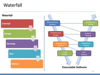
  • 20. Software Process Models 20 • The word ‘Process’ emphasizes the idea of a system in action. In order to achieve an outcome, the system will have to execute one or more activities: This is its process • These activities can be organized in different ways – ‘Process Models’ •A classical Model also known as one-shot or once-through model •A sequence of activities working from Top to Bottom •Best suited where the Requirements are well defined & development methods well understood Waterfall •A Feasibility Study is carried out at the beginning of the project •Greater level of detail is considered at every stage of the project •Portrayed as a loop or a Spiral where the system to be developed is considered in more detail in every step Spiral •The approach is more incremental and iterative •Also called as Dynamic Systems Development Method •8 Core principles: Focus on Business Need, OTD, Collaborate with user, Quality, Iterative Development, Incremental Build, Communicate & Control Atern/DSDM •Also referred to as Rapid Prototyping Model •The major aim is to reduce costs and cycle time and improved Change Management •Increased Customer involvement as feedback is sought on successive developed prototypes which are refined RAD •Designed to overcome important disadvantages of the Traditional Methodologies •The approach involves development of one feature at a time and released to the Customer for their use and feedback •Includes various sub methods: Scrum, XP, Kanban Agile
  • 22. Incremental Process 22 Incremental Process Model Project Calendar Time Software Functionality and Features Communication Planning Modeling (Analysis, Design) Construction (Code, Test) Deployment (Delivery, Feedback) Increment # 1 Delivery of 1st Increment Increment # 2 Delivery of 2nd Increment Increment # n Delivery of nth Increment
  • 23. Quick Plan Modeling Quick Design Construction of Prototype Deployment Delivery & Feedback Communication Evolutionary Process Models 23 Prototyping • Best suited when the Customer defines a set of general objectives but does not identify detailed requirements for functions and features • The developer may be unsure of the efficiency of an algorithm, the adaptability of an operating system or the form that human-machine interaction should take place
  • 24. Spiral Model – Different Phases 24 • An evolutionary software process that couples the iterative nature of prototyping with the controlled and systematic aspects of Waterfall model • The software is developed in a series of evolutionary releases. Early iterations release might be a prototype and later iterations would be more complete versions of the system
  • 25. The Unified Process 25 Inception Elaboration Construction Transition Production •Encompasses both Customer communication & Planning activities •Business requirements (Use Cases) are identified and a rough architecture is proposed •A plan for the iterative, incremental nature of the project is developed •Use cases that were developed as part of the inception phase are refined and expanded •Expands the architecture to include Use Case Model, Analysis Model, Design Model, Implementation Model, and Deployment Model •A first cut executable system representation is done •Using the architectural model as input, the construction phase develops or acquires the components to make the Use case operational •Analysis and design models are completed to reflect the final version of the software increment •All necessary and required functions and features are implemented •Unit tests are designed and executed and integration activities are conducted •Encompasses the delivery and feedback activity •Software is given to end users for beta testing for defects and feedback •The team creates the necessary support information (User manuals, troubleshooting guides, and installation procedures •Ongoing use of the software is monitored •Support for the operating environment (infrastructure)is provided •Defect reports and requests for changes are submitted and evaluated
  • 26. Agile Development What is Agility? • Software development today is driven by change. The pervasiveness of change is the primary driver for Agility • Agility is more than an effective response to change • It encourages team structures and attitudes that make communication between stakeholders more facile • It emphasizes rapid delivery of operational software Agility and the cost of change • The cost of change increases nonlinearly as the project progresses • It is easy to accommodate a change during the upper life cycle especially requirements phase • Changes later in the life cycle require changes across the phases (Requirements, Design, Coding, Testing) • A well defined Agile process flattens the cost of change curve Development Schedule progress Development Costs Cost of change using conventional software processes Cost of change using Agile processes Idealized Cost of change using Agile processes
  • 27. Agile Process 27 Key Assumptions • It is difficult to predict in advance which software requirements will persists and which will change • It is difficult to predict how Customer priorities will change as the project proceeds • For many types of software, the design and construction are interleaved. Both activities should be performed in tandem so that the design models are proven as they are created • Analysis, Design, Construction, and Testing are not as predictable (from a planning point of view) as we might like How do we create a process that can manage unpredictability? • An incremental development strategy should be instituted! • Adaptation keeps pace with change (unpredictability) • This iterative approach enables the Customer to evaluate the software increments regularly, provide necessary feedback to the development team, and influence the process adaptations that are made to accommodate the feedback
  • 28. Agile Principles 28 1. Highest priority is to satisfy the Customer through early and continuous delivery of valuable software 2. Welcome changing requirements even late in development. Agile processes harness change for the Customers competitive advantage 3. Deliver working software frequently, from a couple of weeks to a couple of months with a preference to the shorter time scale 4. Business people and developers must work together daily throughout the project 5. Build projects around motivated individuals, Give them the environment and support they need, and trust them to get the job done 6. The most efficient and effective method of conveying information to and within a development team is face-to-face conversation 7. Working software is the primary measure of progress 8. Agile processes promote sustainable development. The sponsors, developers, and users should be able to maintain a constant pace indefinitely 9. Continuous attention to technical excellence and good design enhances agility 10. Simplicity – the art of maximizing the amount of work done – is essential 11. The best architecture, requirements, and design emerge from self organizing teams 12. At regular intervals the team reflects on how to become more effective, then tunes and adjusts its behavior accordingly
  • 29. Agile – Extreme Programing 29 XP Process: Release – Software increment Refactoring User Stories Values Acceptance test criteria Iteration plan Simple Design CRC Cards Spike solutions Prototypes Pair programming Unit test Acceptance testing Continuous integration
  • 30. Agile Scrum Model 30 Develop Develop Test Reiterate Design Design 1. The Project is divided into sprints of 2 to 4 weeks where incremental functionality is completed and delivered 2. Key Role holders – Product Owner, Scrum Master, Team Member 3. Key Artefacts – Product Backlog, Sprint Backlog, Sprint Burn Down and Burn Up Charts 4. Scrum Ceremonies – Sprint Planning, Daily Scrum, Sprint Review Meeting
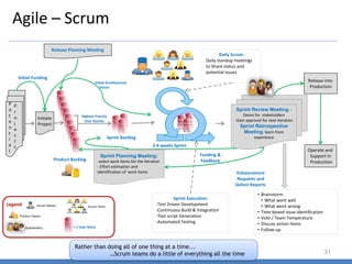
  • 31. Agile – Scrum 31 Product Backlog Initiate Project P o t e n t i a l P r o j e c t s Highest Priority User Stories Sprint Backlog Initial Funding Initial Architectural Vision Release into Production Operate and Support in Production Funding & Feedback Enhancement Requests and Defect Reports Daily Scrum: Daily standup meetings to Share status and potential issues 2-4 weeks Sprint • Brainstorm • What went well • What went wrong • Time-boxed issue identification • Vote / Team Temperature • Discuss action items • Follow-up Sprint Execution: -Test Driven Development -Continuous Build & Integration -Test script Generation -Automated Testing Sprint Review Meeting: - Demo for stakeholders -Gain approval for next iteration Sprint Retrospective Meeting- learn from experience Sprint Planning Meeting: -select work items for the iteration - Effort estimation and identification of work items Release Planning Meeting = 1 User Story Legend Product Owner Scrum Master Stakeholders Scrum Team Rather than doing all of one thing at a time... …Scrum teams do a little of everything all the time
  • 32. Agile – Dynamic Systems Development Method 32 • Provides a framework for building and maintaining systems through the use of incremental prototyping in a controlled environment • An iterative software process in which each iteration follows the 80% rule. Only enough work is required for each increment to facilitate movement to the next increment Functional Model iteration Design and Build Iteration Implementation •Produces a set of incremental prototypes that demonstrate functionality to the Customer •All DSDM prototypes are intended to evolve into deliverable applications •Intent is to gather additional requirements through feedback from users as they exercise the prototype •Revisit and review prototypes that were built during the functional model iteration •In some cases the functional model iteration and the design and build iteration occur concurrently •Places the latest software increment (An operational prototype) into the operational environment •The increment may be 100% complete or changes may be requested as the increment is put into place
  • 33. Agile Unified Process 33 • AUP adopts a “serial in the large” and “iterative in the small” philosophy for building computer based systems • By adopting the classic UP phased activities (Inception, Elaboration, Construction, and Transition) – AUP provides a serial overlay (linear sequence of software engineering activities) Modeling Imlementation Testing •UML representations of the business and problem domains are created •These models should be just barely good enough to allow the team to proceed •Models are translated into source code •Delivery of software increment and acquisition of feedback from the end users Each AUP iteration addresses the following activities: •Like XP, the team designs and executes a series of tests to uncover defects Deployment •Configuration management addresses change management, Risk Management and control of any persistent work products •Project Management tracks and controls the progress of the team and coordinates team activities Configuration and Project Management
  • 34. Agile Methods – Basic Principles 34 • Incremental Delivery after each time box • Features are decomposed into small parts that can be incrementally developed • Each incremental part is developed over an iteration • The Time to develop an iteration is called a time box • Face-to-Face communication • Emphasis on Face-to-Face communication over written documents • Daily contact through communication channels • Customer Interactions • Includes Customer representative in the team • Customer participates in review meetings and provide feedback • Minimal Documentation • Documents are created on a need to know basis • Documentation is light so easy to keep up-to-date and consistent • Pair Programming • In this approach two programmers work together at one station • The programmers switch roles every hour or so • Lesser defects are expected
  • 35. Waterfall V/S Agile 35 Strengths Weaknesses Type of projects Waterfall: 1. Simple projects 2. Clear Requirements 3. Past projects experience 4. Intuitive and logical 1. Requirements frozen early 2. Does not encourage changes 3. Cycle time is too long 4. Late user feedback 1. Projects with very clear requirements 2. Short duration projects 3. Automation of existing manual systems Agile: 1. Regular deliveries 2. Reduces risks 3. Accommodates changes 4. Quick user feedback 5. Prioritizing requirements 1. Requirements spillover from sprints 2. Backlog bloating 3. Possibility of rework and defects 4. System architecture and structure may suffer as frequent changes are made 1. For projects where time is of essence 2. Risk of long projects cannot be taken 3. Requirements are not known and will be known only with time
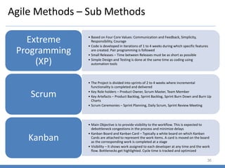
  • 36. Agile Methods – Sub Methods 36 • Based on Four Core Values: Communication and Feedback, Simplicity, Responsibility, Courage • Code is developed in iterations of 1 to 4 weeks during which specific features are created. Pair programming is followed • Small Releases – Time between Releases must be as short as possible • Simple Design and Testing is done at the same time as coding using automation tools Extreme Programming (XP) • The Project is divided into sprints of 2 to 4 weeks where incremental functionality is completed and delivered • Key Role holders – Product Owner, Scrum Master, Team Member • Key Artefacts – Product Backlog, Sprint Backlog, Sprint Burn Down and Burn Up Charts • Scrum Ceremonies – Sprint Planning, Daily Scrum, Sprint Review Meeting Scrum • Main Objective is to provide visibility to the workflow. This is expected to debottleneck congestions in the process and minimize delays • Kanban Board and Kanban Card – Typically a white board on which Kanban Cards are attached to represent the work items. A card is moved on the board as the corresponding work is completed at a stage • Visibility – It shows work assigned to each developer at any time and the work flow. Bottlenecks get highlighted. Cycle time is tracked and optimized Kanban
  • 37. Agile Methods – Kanban Boards example 37
  • 39. What is Project Management? 39 What is Project Management? • Project Management involves the Planning, Monitoring, and control of the People, Process and the Events that occur as project evolves from a preliminary concept to an operational implementation PSI21892 Project Profitability homepage_photo_okfingers Customer Satisfaction newPDRIlogo Quality Management & Operational Focus kmLessonsLearned Knowledge Management team People Management Project Manager
  • 40. Project Management & the 4 P’s 40 Effective Project Management focuses on the 4 Ps: The People • People must be organized into effective teams, motivated to do high quality work The Product • The requirements / pain areas must be communicated from Customer to developer, partitioned into logical parts, and positioned for work by the project team The Process • A common framework with an appropriate process engineering paradigm to come up with a set of tasks The Project • The project needs to be organized in a manner that enables the team to succeed
  • 41. PMI and Framework Overview 41 About PMI? • The PMI was founded by Ned Engman (McDonnel Douglas Automation), James Snyder and Susan Gallagher (SmithKline & French Laboratories), Eric Jenett (Brown & Root) and J Gordon Davis (Georgia Institute of Technology) at the Georgia Institute of Technology in 1969 as a non-profit organization PMI Objectives: • Foster recognition of the need for professionalism in project management • Provide a forum for the free exchange of project management problems, solutions and applications • Coordinate industrial and academic research efforts • Develop common terminology and techniques to improve communications • Provide interface between users and suppliers of hardware and software systems • Provide guidelines for instruction and career development in the field of project management PMI Services: • Development of standards, research, education, publication, networking-opportunities in local chapters, hosting conferences and training seminars, and providing accreditation in project management • PMI has recruited volunteers to create industry standards, such as "A Guide to the Project Management Body of Knowledge", which has been recognized by the American National Standards Institute (ANSI). In 2012 ISO adapted the project management processes from the PMBOK Guide 4th edition PMI India: • PMI India office was established with the sole goal of advancing project management profession and inculcating a project management culture within the establishments across government, academia, and industry -- https://pmi.org.in
  • 42. PMI Framework -- Key Knowledge Areas 42 PMI Integration Management Scope Management Time Management Cost Management Quality Management Human Resources Management Communication Management Risk Management Procurement Management Stakeholder Management
  • 43. Project Initiation 43 Project Life Cycle: Components of Project Initiation: • Project Charter • Project Management Plan Initiating Planning Monitoring & Control Executing Closing
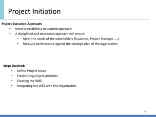
  • 44. Project Initiation 44 Project Execution Approach: • Need to establish a structured approach • A disciplined and structured approach will ensure: • Meet the needs of the stakeholders (Customer, Project Manager……) • Measure performance against the strategic plan of the organization Steps involved: • Define Project Scope • Establishing project priorities • Creating the WBS • Integrating the WBS with the Organization
  • 45. Defining Project Scope 45 Scope definition checklist: • Project Objective • Deliverables • Milestones • Technical Requirements • Limits and Exclusions • Reviews with Customer Project Scope: • Defining the project scope sets the stage for developing a project plan • Project scope is a definition of the end result or mission of the project, a product or service
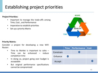
  • 46. Establishing project priorities 46 Priority Matrix: Consider a project for developing a new WiFi Router: • Time to Market is important to sales – Time can be enhanced – reduce completion time • In doing so, project going over budget is acceptable • But original performance specifications cannot be compromised Project Priorities: • Important to manage the trade-offs among Time, Cost , and Performance • Imperative to establish priorities • Set up a priority Matrix Time Performance Cost Constrain Enhance Accept
  • 47. Project Planning -- Estimation 47 What is Estimation? Estimation is a process of forecasting or approximating the time and cost of completion of the project Why Estimating Time and Cost are important? • Estimates are needed to support good decisions • Estimates are needed to schedule work • Estimates are needed to determine how long a project should take and its cost • Estimates are needed to determine whether the project is worth doing • Estimates are needed to develop cash flow needs • Estimates are needed to determine how well the project is progressing Consider this: • Inaccurate Estimates lead to false expectations and Customer dissatisfaction • Accuracy is improved with greater efforts, but is it worth the time and costs? Estimating costs money! • Project Estimates become a trade-off balancing the benefits of better accuracy against the costs for securing increased accuracy • Cost, Time, and Budget estimates are the lifeline for control
  • 48. Project Planning -- Estimation 48 Project Estimation is indeed a yardstick for project cost control. If the yardstick is faulty, you start on the “wrong Foot” Do not Underestimate the Estimate!!
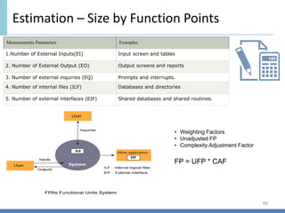
  • 49. Estimation – Size by Function Points 49 Measurements Parameters Examples 1.Number of External Inputs(EI) Input screen and tables 2. Number of External Output (EO) Output screens and reports 3. Number of external inquiries (EQ) Prompts and interrupts. 4. Number of internal files (ILF) Databases and directories 5. Number of external interfaces (EIF) Shared databases and shared routines. • Weighting Factors • Unadjusted FP • Complexity Adjustment Factor FP = UFP * CAF
  • 50. Planning by Use of Baselines 50 Projects Size (FP) Actual Efforts (PDs) Defects Pr1 100 118 (0.84) 200 Pr2 150 183 (0.81) 330 Pr3 175 224 (0.78) 420 Pr4 200 267 (0.74) 540 Pr5 250 329 (0.75) 725 Pr6 500 602 (0.83) 1000 Pr7 750 1071 (0.70) 2250 Pr8 1000 1471 (0.67) 3200 Pr9 1500 2419 (0.62) 5250 Pr10 4000 7273 (0.54) 14400 Pr1 100/118 = 0.847 Pr7 750/1071 = 0.7 Pr2 150/183 = 0.819 Pr10 4000/7273 = 0.549 If the Size is 1200 FPs, How many PDs will I need? Regression Equation PDs = 1.559*FP – 28.85 = (1.559*1200 – 28.85) = 1890 PDs Size Effort . . . . . PDs = 1.559*FP – 28.85
  • 51. Estimation – Size by Function Points 51 International Function Points Users Group IFPUG Size = 1000 FPs Productivity = Size / Efforts = FP / PD 0.7 FP in 1 PD of effort = 0.7/1 FP / PD Baselines (Historical Data) Effort = Size / Productivity = 1000 / 0.7 = 1428.57 = 1429 PDs (Efforts spread across the life cycle)
  • 52. Planning by Use of Baselines 52 Size 0 5000 10000 Pr1 Pr2 Pr3 Pr4 Pr5 Pr6 Pr7 Pr8 Pr9 Pr10 100 150 175 200 250 500 750 1000 1500 4000 118 183 224 267 329 602 1071 1471 2419 7273 Pr1 Pr2 Pr3 Pr4 Pr5 Pr6 Pr7 Pr8 Pr9 Pr10 Size 100 150 175 200 250 500 750 1000 1500 4000 Actual Efforts 118 183 224 267 329 602 1071 1471 2419 7273 Productivity Size Actual Efforts Size 0 5000 10000 15000 Pr1 Pr2 Pr3 Pr4 Pr5 Pr6 Pr7 Pr8 Pr9 Pr10 100 150 175 200 250 500 750 1000 1500 4000 200 330 420 540 725 1000 2250 3200 5250 14400 Pr1 Pr2 Pr3 Pr4 Pr5 Pr6 Pr7 Pr8 Pr9 Pr10 Size 100 150 175 200 250 500 750 1000 1500 4000 Defects 200 330 420 540 725 1000 2250 3200 5250 14400 Defect Density Size Defects
  • 53. Estimation – Type of Costs & Refining 53 Cost Breakdown: 1. Direct Costs: Cost of Labour, Material, Equipment, Others. These costs are clearly chargeable to a specific work package 2. Direct Project Overhead Costs Costs tied to project deliverables or work packages. Salaries….usually a ratio of the dollar value of the resources 3. General & Administrative Overhead Costs: These represent organization costs which are not directly linked to the project. These costs are carried for the duration of the project. (Advertising, Accounting, Senior Management. Generally a % of the total direct costs Refining Estimates: Generally a % of adjustment is done over the original estimates 1. Interaction Costs: Time spent on interaction between departments for queries and issues 2. Normal conditions do not apply: Costs associated when project demonstrates variations from normal assumed conditions 3. Things go wrong on the project: Design flaws, Extreme weather conditions, unplanned leaves…… 4. Changes in Scope and plans: Major changes during execution and change management process 5. Overly optimistic: Tendency to overestimate completion of tasks and underestimate duration 6. Strategic misrepresentation: Underestimation of costs and overestimation of benefits in order to win proposals
  • 54. Work Breakdown Structure 54 What is a WBS?: • A WBS is a deliverables oriented collection of project components • It is a Categorization and Decomposition of the Project Scope Statement • Breaking down the massive project scope statement into smaller more manageable components Why do you need a WBS?: • It serves as an input to 5 key Project Management Activities: • Cost Estimate • Resource Planning • Risk Management Planning • Activity Definition • Defines the work required to be done • Helps in working towards the deliverables – create, manage and control tasks • Help prevent scope change What is a Work Package?: • A work package is the smallest element of the WBS • A WBS element that you can schedule, estimate the costs, and monitor and control Create a Milestone List
  • 55. METRICS IN PROJECT MANAGEMENT
  • 56. Key Areas …. Measurement & Metrics 56 • Measurement enables managers to improve the software process ; assist in the planning, tracking, and control of a software project and access the quality of the product that is developed Process Product Technology People Customer Characteristics Business Conditions Development Environment
  • 57. Metrics 57 “If you don`t know where you are going, any road will do” – CHINESE PROVERB “ If you don`t know where you are, a map won`t help” WATTS S. HUMPHREY “What you cannot measure, you cannot manage-” DRUCKER
  • 58. Introduction 58 • Why Measure? • What to Measure? • Designing a Metrics Program
  • 59. Why Measure? 59 • Objectives of Measurements ✓ For Projects • Proper Estimation & Planning • Tracking progress against plan • Get early warnings • Take timely corrective actions ✓ For Organization • Basis for setting benchmarks • Basis for driving process improvements • Tracking Process performance against Business Objectives (PPM)
  • 60. What to Measure? 60 Basic measures: ✓ Size (e.g., function points, source lines of code, classes, features, etc.) ✓ Efforts (e.g., person days, etc.) ✓ Schedule (e.g., start date, end date, etc.) ✓ Defects (e.g., no. of defects – review & testing, no. of post-delivery defect, etc.) Example of Metrics: ✓ Variance (size, efforts & schedule related) ✓ Productivity (size / effort) ✓Test Case Adequacy, Test Case Effectiveness, Defect Detection Index
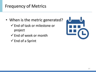
  • 61. Frequency of Metrics 61 • When is the metric generated? ✓End of task or milestone or project ✓End of week or month ✓End of a Sprint
  • 62. Metrics Report Analysis Effort Variance (Actual) Schedule Variance (Actual) Effort Variance (Predicted) Schedule Variance (Predicted) 10% 1% 25% 5% Review Effectiveness Defect Density Defect Removal Efficiency Defect Age 50% 3 Defects / FP 87% >2 Test Case Adequacy Test Case Efficiency 100% 60% Analysis: 1. More effort than planned – (Resources facing Technology issues, roadblocks → schedule slippage, High DD, Low DRE, Low RE, Regression 2. Low RE → Understanding of the requirements, Review process is not streamlined, Skill of the reviewer 3. High DD → Low RE leading to more defects and also due to regression, Coding stds are not followed, Skill of the coder, Issues with the development / implementation process 4. High defect leakage to the Customer, High defect age 5. Low TCE → Quality of Test cases, Complexity of the requirement, Skill of the tester Corrective Action: 1. Revisit the SRS / design for new reviews through SMEs, Increase the review cycles 2. Train the resources in the technology being used 3. Review the development / deployment process 4. Use Best practices for Reviews, coding, replace the inefficient resources, peer reviews & testing 5. Optimise the process, remove unwanted process steps → Save valuable efforts
  • 66. Agile – Metrics & Challenges 66 What to measure? Efforts (Cost), Schedule, Quality of Deliverables, Customer Satisfaction Traditional Methodology: Measurements done at phase level ➢ Size : Function Points, LOC, Use-case Points ➢ Efforts / Cost – Effort Variance / Cost Variance ➢ Schedule – Schedule Variance ➢ Quality – ➢ Defect Density, Review Effectiveness, Defect Removal Efficiency ➢ Efficiency, Test Case Effectiveness ➢ Defect Density – Defects / FP, Defects / KLoc ➢ Defect Age, Defect Acceptance Rate ➢ Critical Chain Concept can be used for effective Buffer Management ➢ Earned Value can be used for prediction / Forecasts to facilitate Proactive Project Management ➢ Customer Satisfaction – Customer Satisfaction Survey / Feedback Agile Methodology: Measurements done at Sprint and Iteration level ➢ Size : Story Points ➢ Efforts / Cost – Effort Variance / Cost Variance ➢ Schedule – Schedule Variance ➢ Quality – ➢ Defect Density – Defects/Story Point, Review Effectiveness, Defect Removal Efficiency ➢ Efficiency, Test Case Effectiveness ➢ Defect Density – Defects / Story Points ➢ Defect Age, Defect Acceptance Rate ➢ Critical Chain Concept can be used for effective Buffer Management ➢ Earned Value can be used for prediction / Forecasts to facilitate Proactive Project Management ➢ Customer Satisfaction – Customer Satisfaction Survey / Feedback Challenges? ▪ Inconsistencies in Size measurements across projects and inadequate baselines ▪ Short Turn around time in a sprint leading to process gaps ▪ Aggressive schedule and stringent deadlines
  • 67. Agile Methods – Challenges 67 • Reluctance to Change • Difficult to break work habits as teams are used to work with a traditional approach. Need to implement Agile in a phased manner with pilot projects • Quality, Cost, Time and Scope • Agile being flexible allows frequent changes in scope which means that Cost, Quality or Time has to change. In practice, majority of projects have fixed budget and a mandatory deadline • Establishing when the scope changes to cease is difficult and hence leads to overruns • Ready to Use Product • An application under agile development process is always evolving and may have functional defects. Hence, performance testing can only be performed after substantial number of deliveries • Inability to ‘design’ for future requirements • Irrespective of best design models and most experienced design personnel on a project team, it is very hard to design a system on the basis of unseen requirements. This often leads to ‘rework’ at various stages in development and testing • External and Internal Dependencies • Majority of projects have external dependencies which are out of control of core project team and they are discovered only during development • The selection of work items is dependent on internal teams, hence planning each iteration becomes tough and needs huge coordination efforts
  • 68. What is Risk Management?: What is a Risk?: Risk Management Overview • An uncertain event or a condition that, if it occurs has a positive or negative impact on one or more project objectives such as Scope, Schedule, Cost, and Quality • A risk is a potential problem – It might happen, it might not • Regardless if the Risks materializes, we need to: • To identify it • Assess its probability of occurrence • Estimate its impact • Establish a contingency plan • If you know the enemy and know yourself, you need not fear the result of a hundred battles – Sun Tzu, a Chinese general • For the Project Manager, the enemy is the Risk! • Risk Analysis and Management are a series of steps that help a project team to understand and manage uncertainty 74
  • 69. Risk Management Process and Event Graph Step 1 Risk Identification Analyse the project to identify sources of Risks Step 2 Risk Assessment Assess Risks in terms of: • severity of impact • Probability of occurring • Controllability Step 3 Risk Response Development • Develop a strategy to reduce possible damage • Develop Contingency Plans Step 4 Risk Response Control • Implement Risk Strategy • Monitor and adjust plans for new Risks • Change Management New Risks New Risks New Risks 75
  • 70. Risk Management Plan Inputs to help plan Risk Management: • Project Scope Baseline • Cost Management Plan • Schedule Management Plan • Communications Management Plan • Enterprise Environment Factors • Organizational Process Assets The Project Manager will work with the Project Team, Key Stakeholders, SME’s, and Management to plan and handle the Risks Key Activities of Risk Management: • Identify the Risks • Analyze the Risks • Creating Risk Responses 76
  • 71. Qualitative Analysis: Identifying the Risks: Risk Management Tasks • Review Project Documents • Brainstorming • Assumption Analysis • Root Cause Analysis • SWOT Analysis • Delphi Technique Analyze the Risks: • The Risks have to be analyzed to determine how probable the risks are to occur and, if the risks do occur, what is the impact of the risk • This is a high level approach and is subjective. The predicted probability and impact can be based on past experience, gut instinct, and other subjective inputs • It uses a Risk Matrix, also called Probability Impact Matrix to score the Risks on an ordinal scale Quantitative Analysis: • This approach quantifies the risk • The risks are tested in a controlled environment whenever possible Risk Responses: • Avoidance – Create workarounds by changing schedule, reducing scope, etc. • Transference – Transfer the Risk to a third party, usually for a fee • Mitigation – To act in order to reduce the Risk probability and impact (Prototype Development 77
  • 72. Risk Breakdown Structure Project Technical External Organization Project Management Requirements Technology Complexity Performance & Reliability Quality Subcontractor s & Suppliers Regulatory Market Customer Weather Project Dependencies Resources Funding Prioritization Estimating Planning Controlling Communication Project
  • 73. Risk Assessment Relative or Numerical Scale Project Objective 1 Very Low 2 Low 3 Moderate 4 High 5 Very High Cost Insignificant cost increase < 10% Cost Increase 10-20% cost increase 20-40% cost increase > 40% cost increase Time Insignificant time increase < 5% time increase 5-10% time increase 10-20% time increase > 20% time increase Scope Scope decrease barely noticeable Minor areas of scope affected Major areas of scope affected Scope reduction unacceptable to sponsor Project end item is effectively useless Quality Quality degradation barely noticeable Only very demanding applications are affected Quality reduction requires sponsor approval Quality reduction unacceptable to sponsor Project end item is effectively useless Risk Event Probability Impact Detection difficulty When Interface problems 4 4 4 Conversion System freezing 2 5 5 Start-up User backlash 4 3 3 Post installation Hardware malfunctioning 1 5 5 Installation Risk Assessment Form Conditions for impact scales of a Risk on major project Objectives 79
  • 74. Risk Severity Matrix Impact Probability Red Zone (Major Risk) Yellow Zone (Moderate Risk) Green Zone (Minor Risk) 1 2 3 4 5 1 2 3 4 5 • The Risk Severity Matrix provides a basis for prioritizing which risks to address • Red Zone risks receive first priority followed by yellow zone risks • Green Zone risks are typically considered inconsequential and ignored unless status changes • Impact is considered more important than Probability (1 10% probability of losing $ 1,000,000 is usually considered a more severe risk than a 90% probability of losing $ 1000) User Backlash Interface problems System freezing Hardware Malfuncti oning • Failure Mode and Effects Analysis extends the Risk Severity Matrix by including ease of detection in the equation • Impact * Probability * Detection = Risk Value 80
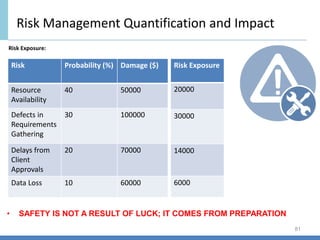
  • 75. Risk Exposure: Risk Management Quantification and Impact Risk Probability (%) Damage ($) Resource Availability 40 50000 Defects in Requirements Gathering 30 100000 Delays from Client Approvals 20 70000 Data Loss 10 60000 Risk Exposure 20000 30000 14000 6000 • SAFETY IS NOT A RESULT OF LUCK; IT COMES FROM PREPARATION 81
  • 76. Risk Contingency Planning • A contingency plan is an alternative plan that will be used if a possible foreseen risk event becomes a reality • The Contingency plan represents actions that will reduce or mitigate the negative impact of the risk event • Contingency plans answers questions of What, Where, When, and How much action will take place • Contingency planning evaluates alternative remedies for possible foreseen events before the risk event occurs and selects the bet plan among alternatives. This early contingency planning facilitates a smooth transition to the remedy or work around plan • The contingency plan should include a cost estimate and identify the source of funding Contingency Funding and time buffers : • Contingency Funds are established to cover project risks • The size and amount of contingency reserves depend on uncertainty inherent in the project • The contingency reserve fund is typically divided into budget and management reserve funds for control purposes • Since all risks are probabilistic, the reserve funds are not included in the baselines. They are only activated when a risk occurs • If an identifies risk does not occur and its chance of occurring is past, the fund allocated to the risk should be deducted from the budget reserve • Time buffers are sometimes added to the end of the project. This would not appear on the schedule, it is available if needed 82
  • 77. Risk Response Control • The Risk Register details all identified risks, including description, probability, impact, contingency plans, owners and current status • Project Managers need to monitor risks just as they monitor project progress • The Risk register needs to be updated at every specified interval Change Control Management : • Most changes fall into the following three categories: • Scope changes in the form of design or addition in functionality • Implementation of contingency plans, when risk events occur, represent changes in baseline costs and schedules • Improvement changes suggested by project stake holders 83
  • 78. Requirements Analysis and Specification 78 “I know you think you understand what I said, but what you don’t understand is what I said is not what I meant” For large Software systems, requirements analysis is perhaps the most difficult and intractable activity and is it is error-prone Why is Requirements Analysis difficult? • The needs of the system are in the minds of the Customer organization • The analyst has to identify the requirements by interacting with the Customer and understanding their needs……visualize • As the information which is visualized, is not formally stated or organized, the input of the requirements phase is inherently informal and imprecise, and is likely to be incomplete • When inputs from multiple people are to be gathered, these inputs are likely to be inconsistent as well • User needs keep changing as the environment in which the system is to function changes with time The requirement process • The requirements phase translates the ideas in the minds of the Customer (the input) into a formal document (the output) • The output is hopefully complete and consistent, while the input has non of these properties • Any formal translation process producing a formal output must have a precise and unambiguous input
  • 79. Software Requirements 79 Requirement • A condition of capability needed by a user to solve a problem or achieve an objective • A condition or capability that must be met or proposed by a system…… to satisfy a contract, standard, specification, or other formal imposed document • Requirements of the proposed system, that is the capabilities that the system, which is yet to be developed should have • Even while accepting that some requirement change requests are inevitable, it is imperative to have a high quality and stable SRS (Software Requirement Specification)
  • 80. Why do we need a high quality and stable SRS? 80 • An SRS establishes the basis for agreement between the Customer and the Supplier on what the software product will do • An SRS provides a reference for validation of the final product • A defect in the SRS will most likely manifest itself as a defect in the final system implementing the SRS • A high quality SRS is a prerequisite to high quality software • Cost of fixing a defect increases almost exponentially as time progresses • A high quality SRS reduces the development costs
  • 81. High quality SRS – High quality & Reduced costs 81 Phase Cost (Person-hours) Requirements 2 Design 5 Coding 15 Acceptance Test 50 Maintenance 150 • Invest an additional 100 person-hours in the requirements phase, an average of 50 new requirement defects will be detected and removed • Distribution of defects that remain after the requirements phase: • 65% in design, 2% in coding, 30% in Testing, 3% in maintenance • Assuming that the 50 defects are detected in the later phases after requirements, the cost of fixing the defects will be: • (32.5*5) + 1*15) + (15*50) + (1.5*150) = 1152 person hours!! • By investing additional 100 person hours in the requirements phase, the development costs could be reduced by 1152 person hours – a net reduction in cost of 1052 person hours • It is estimated that 20% to 40% of the total development effort in a software project is due to rework (mainly due to change in requirements • Cost of requirements phase is roughly 6% of the total project cost. Consider a project with 50 person months of total effort • Requirements phase consume 3 person months • If by spending an additional 33% effort in the requirements phase, we reduce the total requirement change requests by 33% • Total effort due to rework will reduce from 10 to 20 person months resulting a total saving of 5 to 11 person months i.e a saving of 10% to 22% of the total cost!!
  • 82. Requirements process 82 Problem Analysis Product Description Validation Customer / User Needs • The problem domain and the environment are modelled in an effort to understand the system behaviour, constraints, inputs & outputs • Focus is on clearly specifying the requirements in a document • Issues such as representation, specification languages, and tools are addressed to organize and describe the requirements • Focusses on ensuring that what has been specified in the SRS are indeed all the requirements of the software • Making sure that the SRS is of a good quality Validated SRS
  • 83. Problem Analysis 83 • The basic aim of problem analysis is to obtain a clear understanding of the needs of the clients and the users, what exactly is desired from the software and what the constraints on the solution are • The basic principle used in analysis is the same as in any complex task: divide and conquer! • Partition the problem into subproblems and then try to understand each subproblem and its relationship to other subproblems in an effort to understand the total problem Methods of Analysis: Informal Approach Data Flow Modeling Object Oriented Modeling • An approach where no defined methodology is used • The information about the system is obtained by interaction with the client, end users, surveys, study of existing documents, brainstorming • Also referred to as the structured analysis technique uses function based decomposition while modeling the problem • Data Flow diagrams (DFD) and Data Dictionary are created. The system is viewed as a function that transforms the inputs into desired outputs • A partial system is constructed which is used by the clients, users , and developers to gain a better understanding of the problem and the needs • Two approaches – throwaway and evolutionary prototypes Prototyping • The system is viewed as a set of objects (Object Classes). The objects interact with each other through the services they provide • Define the classes by specifying what state information they encapsulate and what services they provide • Identify relationships that exist between objects of different classes
  • 84. Data Flow Diagram (DFD) 84 Restaurant Automation System: Supplier Make Payment Supplier Register Receive Supplies Make Dishes Order Supplies Supplies Sale Register Record Sale Take Order Process Order Produce Bill Payment Customer Check Supply Record Supplies Supplies Order Order Sales Served Meal Bill Bill Money Receipt
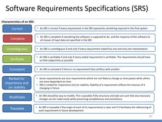
  • 85. Data Dictionary 85 • Supplies_file = [date + [item_no + quantity + cost]* • Order_file = [date + [menu+item_no + quantity + status]*]* • Status = satisfied | unsatisfied • Order = [menu_item_no + quantity]* • Menu = [menu_item_no + name + price + supplies_used]* • Supplies_used = [supply_item_no + quantity]* • Bill = [name + quantity + price]* + total_price + sales_tax + service_charge + grand_total • Discrepancy_report = [supply_item_no + amt_ordered + amt_left + amt_consumed + desr]*
  • 86. Object Oriented Modeling 86 Drug-Store Name Location Compute Sales( ) Sale Amount GetAmount( ) Chemist Name Registration No. Address Compute Sales( ) Medicine Name Quantity Expiry Date Expired ( ) OutofStock ( ) Off-the-shelf Qty-on-shelf GetAmount( ) Prescription Refrigeration Needs Warnings
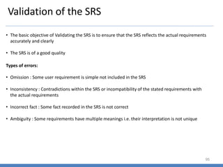
  • 87. Software Requirements Specifications (SRS) 87 Characteristics of an SRS: Correct Complete Unambiguous • An SRS is correct if every requirement in the SRS represents something required in the final system • An SRS is complete if everything the software is supposed to do and the response of the software to all classes of input data are specified in the SRS • An SRS is verifiable if and only if every stated requirement is verifiable. The requirements should have as little subjectivity as possible Verifiable • An SRS is unambiguous if and only if every requirement stated has one and only one interpretation Consistent Ranked for importance and /or stability Modifiable Traceable • An SRS is consistent if there is no requirement that conflicts with another • Some requirements are core requirements which are not likely to change as time passes while others are more dependent on time • SRS is ranked for importance and /or stability. Stability of a requirement reflects the chances of it changing in future • An SRS should be easy to modify. This is possible if the structure and style are such that any necessary changes can be made easily while preserving completeness and consistency • An SRS is traceable if the origin of each of its requirements is clear and if it facilitates the referencing of each requirement in future development
  • 88. Components of an SRS 88 Functionality • Functionality requirements specify which outputs should be produced from the given inputs • They describe the relationship between the input and output of the system • For each functional requirement, a detailed description of all the data inputs and their source, the units of measure, and the range of valid inputs must be specified • All operations to be performed on the input data to obtain the output should be specified. • Specifying the validity checks on the input and output data, parameters affected by the operation, and equations or other logical operations that must be used to transform the inputs into corresponding outputs • The functional specifications must clearly state the system behavior for invalid inputs and invalid outputs
  • 89. Components of an SRS 89 Performance • This part of the SRS specifies the performance constraints on the software system • All the requirements relating to the performance characteristics of the system must be clearly specified • There are two types of performance requirements – Static and Dynamic • Static requirements are those that do not impose constraints on the execution characteristics of the system. These are also called capacity requirements (No. of terminals to be supported, No. of simultaneous users……) • Dynamic requirements specify constraints on the execution behavior of the system (Response time and throughput……) • The functional specifications must clearly state the system behavior for invalid inputs and invalid outputs
  • 90. Components of an SRS 90 Design Constraints • Standards Compliance – This specifies the requirements for the standards the system must follow. For e.g. report format, accounting procedure, audit tracing requirements • Hardware Limitations – The software may have to operate on some existing or predetermined hardware, thus imposing restrictions on the design • Reliability and Fault Tolerance – Requirements about system behavior in the face of certain kinds of faults is specified • Security – Security requirements place restrictions on the use of certain commands, control access to data, different kinds of access requirements for different users, maintain log of activities.
  • 91. Components of an SRS 91 External Interface Requirements • All the interactions of the software with people, hardware, and other software should be clearly specified • For the user interface, the characteristics of each user interface of the software product should be specified • For hardware interface requirements, the SRS should specify the logical characteristics of each interface between the software product and the hardware components. For e.g. memory restrictions, load characteristics…… • The interface requirement should specify the interface with other software the system will use or that will use the system
  • 92. Structure of an SRS 92 1. Introduction 1.1 Purpose 1.2 Scope 1.3 Definitions, Acronyms, and Abbreviations 1.4 References 1.5 Overview 2. Overall Description 2.1 Product Perspective 2.2 Product Functions 2.3 User Characteristics 2.4 General Constraints 2.5 Assumptions and Dependencies 3. Specific Requirements
  • 93. Functional Specifications with Use Cases 93 Term Definition Actors A person or a system which uses the system being built for achieving some goal Primary Actor The main actor for whom a use case is initiated and whose goal satisfaction is the main objective of the use case Scenario A set of actions that are performed to achieve a goal under some specified conditions Main success scenario Describes the interaction if nothing fails and all steps in the scenario succeed Extension scenario Describe the system behavior if some steps in the main scenario do not complete successfully • A use case is a written description of how users will perform tasks on the system • It outlines, from a user's point of view, a system's behavior as it responds to a request • Each use case is represented as a sequence of simple steps, beginning with a user's goal and ending when that goal is fulfilled.
  • 94. Use Case Example 94 * Use Case 1: Put an item for auction Primary Actor: Seller Precondition: Seller has logged in Main Success Scenario: 1. Seller posts an item (its category, description, picture, etc.) for auction 2. System shows past prices of similar items to seller 3. Seller specifies the starting bid price and a date when auction will close 4. System accepts the item and posts it Exception Scenarios: - 2 a) There are no past items of this category * System tells the seller this situation * Use Case 2: Make a bid
  • 95. Validation of the SRS 95 • The basic objective of Validating the SRS is to ensure that the SRS reflects the actual requirements accurately and clearly • The SRS is of a good quality • Omission : Some user requirement is simple not included in the SRS • Inconsistency : Contradictions within the SRS or incompatibility of the stated requirements with the actual requirements • Incorrect fact : Some fact recorded in the SRS is not correct • Ambiguity : Some requirements have multiple meanings i.e. their interpretation is not unique Types of errors:
  • 96. Software Architecture 96 • At a top level, architecture is a design of a system which gives a very high level view of the parts of the system and how they are related to form the whole system • Architecture partitions the system in logical parts such that each part can be comprehended independently, and then describes the system in terms of these parts and the relationship between these parts • Understanding and communication : • To communicate the system to the various stakeholders (Users, Clients, developers) • The stakeholders gain an understanding of some macro properties of the system and how the system intends to fulfill the functional and quality requirements • Reuse : • One of the main techniques by which productivity can be improved, thereby reducing the cost of the software • Construction and Evolution: • Some architecture provided partitioning can be used for constructing the system • Analysis: • It is highly desirable if some important properties about the behaviour of the system can be determined before the system is actually built (analyse the response time and throughput for a web site to be developed) Important uses of architecture:
  • 97. Architecture Views 97 • Module: • The system is viewed as a collection of code units, each implementing some part of the system functionality • These views are code based and do not explicitly represent any runtime structure of the system (Packages, a class, a procedure, a method……) • Component and connector : • The system is viewed as a collection of runtime entities called components. A component is a unit which has an identity in the existing system (Objects, a collection of objects, a process……) • Components provide means for interaction with others (shared data, middleware……) • Allocation: • Focuses on how the different software units are allocated to resources like hardware, file systems, and people. Architecture of Software system C&C Views Runtime Structures Module Views Code Structures Allocation Views Software & Environment co-structures
  • 98. Function Oriented Design 98 • A design methodology is a systematic approach to creating a design by applying of a set of techniques and guidelines • The design process has two levels: • At the first level, the focus is on deciding which modules are needed for the system, the specifications of these modules and how the modules should be implemented – system design or top level design • In the second level, the internal design of the modules, or how the specifications of the module can be satisfied is decided – detailed design or logic design • Efficiency: • Proper use of scarce resources by the system – cost considerations • If some resources are scarce and expensive, it is desirable to use them efficiently (Processor time and memory) • Simplicity : • Most important quality criteria for software systems • Maintainability of the software is one of the established goals Design Principles:
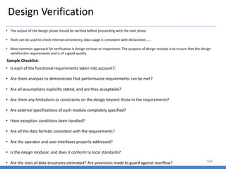
  • 99. Design Principles 99 • Problem partitioning and Hierarchy: • The goal is to divide the problem into manageable small pieces that can be solved separately • The cost of solving the entire problem is more than the sum of the cost of solving al the pieces • The design produced by using problem partitioning can be represented as a hierarchy of components • Abstraction : • An abstraction of a component describes the external behaviour of the of that component without bothering with the internal details that produce the behaviour • Functional and Data abstraction are common abstraction mechanisms: • In functional abstraction, a module is specified by the function it performs (A module to compute the log of a value can be abstractly represented by the function log • In data abstraction, the system is viewed as a set of objects providing some services • Modularity: • A system is considered modular if it consists of discrete components so that each component can be implemented separately, and a change to one component has minimal impact on other components • Top-Down and Bottom-Up Strategies: • The top-down approach starts from the highest level component of the hierarchy and proceeds through to lower levels • The bottom-up approach starts with the lowest level component of the hierarchy and proceeds through progressively higher levels to the top level component
  • 100. Object Oriented Design 100 • OOA and OOD: • The Analysis deals with the problem domain while design deals with the solution domain • OOA models the problem domain leading to an understanding and specification of the problem, while OOD models the solution to the problem Problem Domain Representation Solution Domain Representation Real World Problem Analysis Design Relationship between OOA and OOD
  • 101. Unified Modeling Language (UML) 101 • Unified Modeling Language is a graphical notation for expressing object oriented designs . UML helps build designs that are more likely to satisfy all the requirements of the system • UML is an aid for understanding the system, designing the system, as well as a notation for representation design Key concepts: • Class Diagram: • Represent the static structure of the system or capture what is the structure of the code that will implement it and how the classes in the code are related • Defines the classes that exist in the system – key fields as well as the methods of the classes • Association between classes • Subtype, subtype relationship – classes may also form subtypes giving type hierarchies • Sequence and Collaboration Diagrams: • Also called as interaction diagrams, it represents how the system behaves when it performs some of its functions • Captures the behaviour of the use case and models how the different objects in the system collaborate to implement the use case • Drawn to model the interaction between the objects for a particular use case • Other diagrams and Capabilities: • Apart from Static and Dynamic behaviour, there are many other aspects that might need to be modelled such as specifying notation for components • Also provide a notation for a subsystems, and packages (collection of many elements)
  • 103. Design Methodology 103 • The design methodology for producing an OO design consists of the following steps: Sequence of steps: • Produce the class diagram: • Produce the dynamic model and use it to define operations on classes: • Produce the functional model and use it to define operations on classes: • Identify internal classes and operations • Optimize and package
  • 104. Design Verification 104 • The output of the design phase should be verified before proceeding with the next phase • Tools can be used to check internal consistency, data usage is consistent with declaration…… • Most common approach for verification is design reviews or inspections. The purpose of design reviews is to ensure that the design satisfies the requirements and is of a good quality Sample Checklist: • Is each of the functional requirements taken into account?: • Are there analyses to demonstrate that performance requirements can be met? • Are all assumptions explicitly stated, and are they acceptable? • Are there any limitations or constraints on the design beyond those in the requirements? • Are external specifications of each module completely specified? • Have exception conditions been handled? • Are all the data formats consistent with the requirements? • Are the operator and user interfaces properly addressed? • Is the design modular, and does it conform to local standards? • Are the sizes of data structures estimated? Are provisions made to guard against overflow?
  • 105. Software Testing 105 Testing is the process of executing a program with the intent of finding errors What is Software Testing: Black Box Testing: White Box Testing: • The program is viewed as a black box. Also called a data driven testing • The goal is to be completely unconcerned about the internal behavior or structure of the program • concentrate on finding circumstances in which the program does not behave according to its specifications • permits you to examine the internal structure of the program. Also called as Logic driven testing • This strategy derives test data from an examination of the program’s logic
  • 106. Software Testing Principles 106 Sr. No. Principle 1 A necessary part of a test case is a definition of the expected output or result 2 A programmer should avoid attempting to test his or her own program. 3 Test cases must be written for input conditions that are invalid and unexpected, as well as for those that are valid and expected 4 Examining a program to see if it does not do what it is supposed to do is only half the battle; the other half is seeing whether the program does what it is not supposed to do 5 Avoid throwaway test cases unless the program is truly a throwaway program 6 Do not plan a testing effort under the tacit assumption that no errors will be found 7 The probability of the existence of more errors in a section of a program is proportional to the number of errors already found in that section 8 Testing is an extremely creative and intellectually challenging task
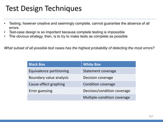
  • 107. Test Design Techniques 107 • Testing, however creative and seemingly complete, cannot guarantee the absence of all errors • Test-case design is so important because complete testing is impossible • The obvious strategy, then, is to try to make tests as complete as possible What subset of all possible test cases has the highest probability of detecting the most errors? Black Box White Box Equivalence partitioning Statement coverage Boundary value analysis Decision coverage Cause-effect graphing Condition coverage Error guessing Decision/condition coverage Multiple-condition coverage
  • 108. Test Design Techniques (Black Box) 108 Equivalence Partitioning: • when testing a program, you are limited to a small subset of all possible inputs • you want to select the ‘‘right’’ subset, that is, the subset with the highest probability of finding the most errors • you should try to partition the input domain of a program into a finite number of equivalence classes such that • you can reasonably assume (but, of course, not be absolutely sure) that a test of a representative value of each class is equivalent to a test of any other value • if one test case in an equivalence class detects an error, all other test cases in the equivalence class would be expected to find the same error • Conversely, if a test case did not detect an error, we would expect that no other test cases in the equivalence class would fall within another equivalence class External Condition Valid Equivalence Classes Invalid Equivalence Classes • The equivalence classes are identified by taking each input condition (usually a sentence or phrase in the specification) and partitioning it into two or more groups • valid equivalence classes represent valid inputs to the program, and invalid equivalence classes represent all other possible states of the condition (i.e., erroneous input values)
  • 109. Test Design Techniques (Black Box) 109 1. If an input condition specifies a range of values (e.g., ‘‘the item count can be from 1 to 999’’), identify one valid equivalence class (1<item count<999) and two invalid equivalence classes (item count<1 and item count>999) 2. If an input condition specifies the number of values (e.g., ‘‘one through six owners can be listed for the automobile’’), identify one valid equivalence class and two invalid equivalence classes (no owners and more than six owners) 3. If an input condition specifies a set of input values, and there is reason to believe that the program handles each differently (‘‘type of vehicle must be BUS, TRUCK, TAXICAB, PASSENGER, or MOTORCYCLE’’), identify a valid equivalence class for each and one invalid equivalence class (‘‘TRAILER,’’ for example). 4. If an input condition specifies a ‘‘must-be’’ situation, such as ‘‘first character of the identifier must be a letter,’’ identify one valid equivalence class (it is a letter) and one invalid equivalence class (it is not a letter) Examples of Equivalence Classes:
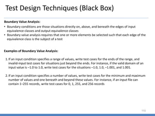
  • 110. Test Design Techniques (Black Box) 110 Boundary Value Analysis: • Boundary conditions are those situations directly on, above, and beneath the edges of input equivalence classes and output equivalence classes • Boundary value analysis requires that one or more elements be selected such that each edge of the equivalence class is the subject of a test 1.If an input condition specifies a range of values, write test cases for the ends of the range, and invalid-input test cases for situations just beyond the ends. For instance, if the valid domain of an input value is –1.0 to 1.0, write test cases for the situations –1.0, 1.0, –1.001, and 1.001. 2.If an input condition specifies a number of values, write test cases for the minimum and maximum number of values and one beneath and beyond these values. For instance, if an input file can contain 1–255 records, write test cases for 0, 1, 255, and 256 records Examples of Boundary Value Analysis:
  • 111. Test Design Techniques (Black Box) 111 Cause Effect Mapping: • One weakness of boundary value analysis and equivalence partitioning is that they do not explore combinations of input circumstances • The testing of input combinations is not a simple task because even if you equivalence-partition the input conditions, the number of combinations usually is astronomical • Cause-effect graphing aids in selecting, in a systematic way, a high-yield set of test cases. It has a beneficial side effect in pointing out incompleteness and ambiguities in the specification Process: • The specification is divided into workable pieces • The causes and effects in the specification are identified. A cause is a distinct input condition or an equivalence class of input conditions • An effect is an output condition or a system transformation • You identify causes and effects by reading the specification word by word and underlining words or phrases that describe causes and effects • The semantic content of the specification is analyzed and transformed into a Boolean graph linking the causes and effects – Cause-effect graph • By methodically tracing state conditions in the graph, you convert the graph into a limited- entry decision table. Each column in the table represents a test case
  • 112. Test Design Techniques (Black Box) 112 Example of Cause Effect Mapping: • The character in column 1 must be an ‘‘A’’ or a ‘‘B.’’ • The character in column 2 must be a digit. In this situation, the file update is made • If the first character is incorrect, message X12 is issued. If the second character is not a digit, message X13 is issued The Causes: 1.character in column 1 is ‘‘A’’ 2.character in column 1 is ‘‘B’’ 3.character in column 2 is a digit The Effects: 1.70—update made 2.71—message X12 is issued 3.72—message X13 is issued
  • 113. Test Design Techniques (Black Box) 113 Error Guessing: • It has often been noted that some people seem to be naturally adept at program testing. Without using any particular methodology such as boundary value analysis of cause-effect graphing, these people seem to have a knack for sniffing out errors • One explanation for this is that these people are practicing—subconsciously more often than not—a test-case design technique that could be termed error guessing • Given a particular program, they surmise—both by intuition and experience—certain probable types of errors and then write test cases to expose those errors
  • 114. Software Reliability 114 • It is desirable to know, in quantifiable terms, the reliability of the software being delivered • As testing directly impacts the reliability, most reliability models use data obtained during testing to predict reliability • Reliability of software depends considerably on the quality if testing. By assessing reliability we can also judge the quality of testing • Reliability of a product specifies the probability of failure-free operation of that product for a given time duration • Reliability is a probabilistic measure that assumes that the occurrence of failure of software is a random phenomenon • If X is the random variable that represents the life of a system, the Reliability of a system is the probability that the system has not failed by time t. • R(t) = P(X>t) • The reliability of a system can also be specified as the mean time to failure (MTTF). MTTF represents the expected lifetime of the system
  • 115. Change Control System Change Originates Change Request Submitted Review Change Request Approved? Update Plan of Record Distribute for action Yes No • Every approved change must be identified and integrated into the plan of record through the WBS and baseline schedule • It is imperative to keep the process updated, changes communicated to the relevant stakeholders • Project control depends heavily on keeping the change control process current • The historical record can be used for satisfying customer inquiries, identifying problems in post –project audits, and estimating future project costs 84
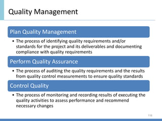
  • 116. Quality Management 116 Plan Quality Management • The process of identifying quality requirements and/or standards for the project and its deliverables and documenting compliance with quality requirements Perform Quality Assurance • The process of auditing the quality requirements and the results from quality control measurements to ensure quality standards Control Quality • The process of monitoring and recording results of executing the quality activities to assess performance and recommend necessary changes