SlideShare a Scribd company logo
International Research Journal of Engineering and Technology (IRJET) e-ISSN: 2395-0056
Volume: 06 Issue: 04 | Apr 2019 www.irjet.net p-ISSN: 2395-0072
© 2019, IRJET | Impact Factor value: 7.211 | ISO 9001:2008 Certified Journal | Page 1850
ARDUINO NANO BASED ALL IN ONE METER
K. Sai Rakesh1, P. SriRaghavendra2, R.S.V.Shivaram3, T.ch.Bhanuteja4
1,2,3,4Student, Pragati Engineering College, Surampalem, Andhra Pradesh, INDIA
---------------------------------------------------------------------***----------------------------------------------------------------------
Abstract - The main objective of this project is to build an
Arduino nano based All in one meter, a device that canbeused
to measure the voltage, current and the power consumed by a
load. There are number of ways that you can implement the
Arduino nano based all in one meter Project. One of the easy
ways is to interface a Voltage Sensor and a Current Sensor
with Arduino, measure the voltage and current values and
finally with some mathematics, you can calculatethePower in
Watts. The Sensor Part of the circuit is responsible for
measuring the Voltage across the load and Current through
the load. Both these values, which are analog in nature, are
given to the Arduino to its ADC. Arduino converts these values
to digital values and makes a few calculations as displays the
results on the LCD.
Key Words: Microcontroller,Sensorunit,AurdinoBoard,
Wattmeter, Measuring Instruments.
1. INTRODUCTION
As electrical engineers, we always depend upon
meters/instruments to measure and analyse the working of
a circuit. Starting with a simple multimeter to a complex
power quality analysers or DSOs everything has their own
unique applications. Most of these meters are readily
available and can be purchased based on the parameters to
be measured and their accuracy. But sometimes we might
end up in a situation where we need to build our own
meters. Say for instance you are working on a solar PV cell
and you would like to calculate the power consumption of
your load, in such scenarios we can build our own
Wattmeter using a simple microcontroller platform like
Arduino.
1.1 Measuring Instruments:
A measuring instrument is a device for measuring a physical
quantity. In the physical sciences, quality assurance, and
engineering, measurement is the activity of obtaining and
comparing physical quantities of real-world objects and
events. Established standard objects and events are used as
units, and the process of measurement gives a number
relating the item under study and the referenced unit of
measurement. Measuring instruments, and formal test
methods which define the instrument's use, are the means
by which these relations of numbers are obtained. All
measuring instruments are subject to varying degrees of
instrument error and measurement uncertainty.
These instruments may range from simple objects such as
rulers and stopwatches to electron microscopesandparticle
accelerators. Virtual instrumentation is widely used in the
development of modern measuring instruments.
Fig -1: Classification of Instruments
1.2 Ammeter
The meter uses for measuring the current is known as the
ammeter. The current is the flow of electrons whose unit is
ampere. Hence the instrument which measures the flows of
current in ampere is known as ampere meter or ammeter.
The ideal ammeter has zero internal resistance. But
practically the ammeter has small internal resistance. The
measuring range of the ammeter depends on the value of
resistance. The ammeter is connected in series with the
circuit so that the whole electrons of measurand current
passes through the ammeter. The power loss occurs in
ammeter because of the measurand current and their
internal resistance. The ammeter circuit has low resistance
so that the small voltage drop occurs in the circuit.
Fig -2: Ammeter
1.3 Aurdino
In default the Arduino is not equipped with a display to
visualize measuring-data, for example from your
International Research Journal of Engineering and Technology (IRJET) e-ISSN: 2395-0056
Volume: 06 Issue: 04 | Apr 2019 www.irjet.net p-ISSN: 2395-0072
© 2019, IRJET | Impact Factor value: 7.211 | ISO 9001:2008 Certified Journal | Page 1851
temperature or your pressure Sensor. If you want to get the
data shown you need a PC, printing the data totheconsole or
mounting a display directly to the Arduino. So there is no
simple way to WIRELESSLY visualizemeasuring-data.Inthis
intractableFig.2will showhowto transfer measuredSensor-
data in real-time from your Arduino-Microcontroller to
your Android-Smartphone via Bluetooth.
Fig -3: Bluetooth HC-05 and Arduino
2. PROBLEM FORMULATION
It is difficult or sometimes even impossible to measure
current, voltage and power at a time with ordinary
multimeters and watt meters. It is very expensive to
measure low power ratings with normal wattmeter and
multimeter
To overcome these disadvantages we are going to design a
special type of meter with Arduino nano microcontroller
with the help of the Arduino Microcontroller we can
measure voltage current and power at a time.
2.1 Existing Technology
The entire project can be divided into three basic blocks;
1) Power Sensor Unit
2) Processor Unit
3) Display Unit
The Power Sensor Unit allows the current to flow through a
device whose power consumption needs to be measured.
The Sensor Unit produces two voltages, one is the Voltage
output from the power supply and another one is a voltage
which ranges from 0 to 5V. The difference between these
two voltages is proportional to the amount of Current
flowing through the Sensor unit. The ProcessorUnitcantake
two input voltages both in the range of 0 to 5V. This unit
takes the Sensor Unit’s output as input voltages and usesthe
ADC to read these voltages. An Algorithm is then applied to
calculate the Power consumptionofthedevice.Theunitthen
sends a 4bit data to the Display Unit to display the power
consumption in Watts. The Display Unit takes the 4bit data
from the Processor Unit and produces a 16*2 display for the
current consumption of the device.
Fig -4: Block diagram
2.2 Proposed Technology
The circuit is designed to fit into systems operatingbetween
0-24V with a current range of 0-1A keeping in mind the
specification of small applications. But you can easilyextend
the range once you understand the working of the circuit.
The underlying principle behind the circuitistomeasurethe
voltage across the load and current through it to calculate
the power consumes by it. All the measured values will be
displayed in a 16*2 Alphanumeric LCD. For ease of
understanding the arduino wattmetercircuitissplitinto two
units. The upper part of the circuit is the measuring unit and
the lower part of the circuit is the computation and display
unit.
3. Hardware Implementation
The measuring unit consists of a potential divider to help us
measure the voltage and a shut resistorwitha Non-Inverting
Op-amp is used to help us measure the current through the
circuit. The output voltage of a potential divider can be
calculated using the below formulae. The same be used to
decide the value of your resistors, you can use our online
calculator to calculate value of resistor if you are re-
designing the circuit. Next we have to measure the current
through the LOAD. As we know microcontrollers can read
only analog voltage, so we need to somehow convert the
value of current to voltage. It can be done by simply addinga
resistor (shunt resistor) in the path which according to
Ohm’s law will drop a value of voltage across it that is
proportional to the current flowing through it. The value of
this voltage drop will be very less so we use an op-amp to
amplify it. The circuit for the same is shown below. Here in
our case the value of Rf is 20k and the value of Rin is 1k
which gives us a gian value of 21. The amplified voltageform
the Op-amp is then given to a RC filter with resistor 1k and a
capacitor 0.1uF to filter any noise that is coupled. Finally the
voltage is then fed to the Arduino analog pin.
International Research Journal of Engineering and Technology (IRJET) e-ISSN: 2395-0056
Volume: 06 Issue: 04 | Apr 2019 www.irjet.net p-ISSN: 2395-0072
© 2019, IRJET | Impact Factor value: 7.211 | ISO 9001:2008 Certified Journal | Page 1852
Fig -5: Schematic diagram
4.1 Working
The Arduino Nano has a number of facilities for
communicating with a computer, another Arduino, or other
microcontrollers. The ATmega328 provide UART TTL (5V)
serial communication, which is available on digital pins 0
(RX) and 1 (TX). An FTDI FT232RL on the board channels
this serial communication over USB and the FTDI drivers
(included with the Arduino software) provide a virtual com
port to software on the computer. The Arduino software
includes a serial monitor which allows simpletextual data to
be sent to and from the Arduino board. The RX and TX LEDs
on the board will flash when data is being transmitted via
the FTDI chip and USB connection to the computer (but not
for serial communication on pins 0 and 1). A SoftwareSerial
library allows for serial communication on any oftheNano's
digital pins.
Fig -6: Arduino nano
4.2 Results
This kit explains about the project “Arduino Nano All in One
Meter” .In this project when supply is givenarduinoandLCD
are powered up. Power supply is adjusted to 24v with the
help of RPS. When the load is connected voltage, currentand
power values are displayed on the LCD.
Fig -7: Arduino nano all in one meter
5. CONCLUSION
This is a project based on Arduino board which can
measures the voltage, currentandpowerconsumptionofthe
devices at a time. When we connect this wattmeter on to a
device which is in operation, the 16*2 LCD displays its
voltage value in volts, current value in amperes and power
consumption value in Watts. The project uses an Arduino
pro mini board whose ADC feature is used along with the
concept of Ohm’s law and Voltage Divider circuit to develop
this Wattmeter. This project is cost friendly and have less
complexity. This project gives more accurate results for the
parameters.
6. FUTURE SCOPE
This Arduino based all in one meter project has many more
upgrades that can be added to increase the performance to
auto data logging, plotting graph, notifying over voltage or
over current situations etc. Also we can add other
parameters like energy , power factor etc by changing the
source code. By changing the component ratings in the
circuit we can measure high loads.
REFERENCES
1) HernandoBarragán(2016-01-01). "TheUntoldHistoryof
Arduino"
2) “Programming Arduino”, book by “Simon Monk”
3) https://circuitdigest.com/microcontroller-
projects/arduino-wattmeter-to-measure-voltage-
current-power-consumption
4) https://meettechniek.info/diy-instruments/arduino-
wattmeter.html
5) https://www.electronicshub.org/arduino-wattmeter/

More Related Content

What's hot (20)

PDF
IRJET- Water Pump Controller using Arduino UNO
IRJET Journal
 
PDF
IRJET - Speed Control of DC Motor by using IoT
IRJET Journal
 
PDF
IRJET - Lie Detector using MATLAB, Arduino and Biomedical Sensors
IRJET Journal
 
PDF
Automatic Room Lights Controller Using Arduino & PIR Sensor
Ankit Chaudhary
 
PDF
IRJET- Sensors implementation in AGV & IoT based data visualization over clie...
IRJET Journal
 
PDF
IRJET- Design of a Portable Contact-Less Tachometer using Infrared Sensor for...
IRJET Journal
 
PDF
Major Project Synopsis Report on IoT based DC Motor Through a Web-site
Utkarsh Chaubey
 
PDF
Development of Android Controlled AC Dim Light
ijtsrd
 
PPTX
IR BASED HOME AUTOMATION USING ARDUINO UNO
Mln Phaneendra
 
PDF
Home Automation System
MOHAMMAD TANVEER
 
PDF
IRJET- Testing the Induction Motor Voltage, Current, Torque, Speed, Power and...
IRJET Journal
 
PDF
IRJET - Expansion of Logic Gates using Trainer
IRJET Journal
 
PPTX
REAL TIME AUTOMATION FOR COLLEGES
Nishmi Suresh
 
PPTX
Automatic Room Light Controller Using Arduinom & PIR Sensor
Ankit Chaudhary
 
PDF
IRJET- Automatic Electric Meter Reading using Wifi
IRJET Journal
 
PPTX
A major project report on Energy Efficient Infrared (IR) Based Home Automatio...
Prasant Kumar
 
PPTX
Sensors in IOT
ATS SBGI MIRAJ
 
PDF
Electrical installation handbook part-1
Souvik Dutta
 
PPTX
Bidirect visitor counter
Electric&elctronics&engineeering
 
PPTX
Automatic DC Fan using LM35 (english version)
Nurlatifa Haulaini
 
IRJET- Water Pump Controller using Arduino UNO
IRJET Journal
 
IRJET - Speed Control of DC Motor by using IoT
IRJET Journal
 
IRJET - Lie Detector using MATLAB, Arduino and Biomedical Sensors
IRJET Journal
 
Automatic Room Lights Controller Using Arduino & PIR Sensor
Ankit Chaudhary
 
IRJET- Sensors implementation in AGV & IoT based data visualization over clie...
IRJET Journal
 
IRJET- Design of a Portable Contact-Less Tachometer using Infrared Sensor for...
IRJET Journal
 
Major Project Synopsis Report on IoT based DC Motor Through a Web-site
Utkarsh Chaubey
 
Development of Android Controlled AC Dim Light
ijtsrd
 
IR BASED HOME AUTOMATION USING ARDUINO UNO
Mln Phaneendra
 
Home Automation System
MOHAMMAD TANVEER
 
IRJET- Testing the Induction Motor Voltage, Current, Torque, Speed, Power and...
IRJET Journal
 
IRJET - Expansion of Logic Gates using Trainer
IRJET Journal
 
REAL TIME AUTOMATION FOR COLLEGES
Nishmi Suresh
 
Automatic Room Light Controller Using Arduinom & PIR Sensor
Ankit Chaudhary
 
IRJET- Automatic Electric Meter Reading using Wifi
IRJET Journal
 
A major project report on Energy Efficient Infrared (IR) Based Home Automatio...
Prasant Kumar
 
Sensors in IOT
ATS SBGI MIRAJ
 
Electrical installation handbook part-1
Souvik Dutta
 
Bidirect visitor counter
Electric&elctronics&engineeering
 
Automatic DC Fan using LM35 (english version)
Nurlatifa Haulaini
 

Similar to IRJET- Arduino Nano based All in One Meter (20)

PDF
IOT BASED SMART ENERGY METER USING ARDUINO UNO
IRJET Journal
 
PDF
IRJET - ATMEGA 328P based Smart Energy Meter Test Jig using PLX-DAX
IRJET Journal
 
PDF
IoT-based Solar Energy Monitoring
IRJET Journal
 
PDF
Electricity Theft: Reason and Solution
IRJET Journal
 
PDF
WIRELESS POWER THEFT MONITORING SYSTEM IN POWER LINES
IRJET Journal
 
PDF
Report
Rakesh Bali
 
PDF
Real-Time Load Monitoring By Microcontroller to Optimize Electric Power Utili...
IJERA Editor
 
PDF
IRJET- V-I Characteristics Plotter
IRJET Journal
 
PDF
IRJET- Monitoring and Measurement of Solar Parameters using IoT
IRJET Journal
 
PDF
IRJET- Solar Powered Transmission Line Inspection Robot
IRJET Journal
 
PDF
IRJET- Arduino based Single Phase Fault Detection System using IoT
IRJET Journal
 
PDF
IRJET- Wireless Data Monitoring and Fault Identification by using IoT in Ther...
IRJET Journal
 
PDF
IRJET- IoT based Industrial Level Sensor Data Acquisition & Monitoring
IRJET Journal
 
PDF
Power Factor Detection and Data Analytics
IRJET Journal
 
PDF
IRJET- Three Phase Fault Analysis in Three Phase Distribution Line
IRJET Journal
 
PDF
ENERGY METER READING SYSTEM WITH AUTOMATIC BILLING USING CLOUD
IRJET Journal
 
PDF
ENERGY METER READING SYSTEM WITH AUTOMATIC BILLING USING CLOUD
IRJET Journal
 
PDF
IRJET- Items’ Filling System Prototype with Sorting System According to the C...
IRJET Journal
 
PDF
IRJET - Footstep Power Generation using Piezo Electric Sensor
IRJET Journal
 
PDF
IRJET- PLC Based Intelligent Control of Substation
IRJET Journal
 
IOT BASED SMART ENERGY METER USING ARDUINO UNO
IRJET Journal
 
IRJET - ATMEGA 328P based Smart Energy Meter Test Jig using PLX-DAX
IRJET Journal
 
IoT-based Solar Energy Monitoring
IRJET Journal
 
Electricity Theft: Reason and Solution
IRJET Journal
 
WIRELESS POWER THEFT MONITORING SYSTEM IN POWER LINES
IRJET Journal
 
Report
Rakesh Bali
 
Real-Time Load Monitoring By Microcontroller to Optimize Electric Power Utili...
IJERA Editor
 
IRJET- V-I Characteristics Plotter
IRJET Journal
 
IRJET- Monitoring and Measurement of Solar Parameters using IoT
IRJET Journal
 
IRJET- Solar Powered Transmission Line Inspection Robot
IRJET Journal
 
IRJET- Arduino based Single Phase Fault Detection System using IoT
IRJET Journal
 
IRJET- Wireless Data Monitoring and Fault Identification by using IoT in Ther...
IRJET Journal
 
IRJET- IoT based Industrial Level Sensor Data Acquisition & Monitoring
IRJET Journal
 
Power Factor Detection and Data Analytics
IRJET Journal
 
IRJET- Three Phase Fault Analysis in Three Phase Distribution Line
IRJET Journal
 
ENERGY METER READING SYSTEM WITH AUTOMATIC BILLING USING CLOUD
IRJET Journal
 
ENERGY METER READING SYSTEM WITH AUTOMATIC BILLING USING CLOUD
IRJET Journal
 
IRJET- Items’ Filling System Prototype with Sorting System According to the C...
IRJET Journal
 
IRJET - Footstep Power Generation using Piezo Electric Sensor
IRJET Journal
 
IRJET- PLC Based Intelligent Control of Substation
IRJET Journal
 
Ad

More from IRJET Journal (20)

PDF
Enhanced heart disease prediction using SKNDGR ensemble Machine Learning Model
IRJET Journal
 
PDF
Utilizing Biomedical Waste for Sustainable Brick Manufacturing: A Novel Appro...
IRJET Journal
 
PDF
Kiona – A Smart Society Automation Project
IRJET Journal
 
PDF
DESIGN AND DEVELOPMENT OF BATTERY THERMAL MANAGEMENT SYSTEM USING PHASE CHANG...
IRJET Journal
 
PDF
Invest in Innovation: Empowering Ideas through Blockchain Based Crowdfunding
IRJET Journal
 
PDF
SPACE WATCH YOUR REAL-TIME SPACE INFORMATION HUB
IRJET Journal
 
PDF
A Review on Influence of Fluid Viscous Damper on The Behaviour of Multi-store...
IRJET Journal
 
PDF
Wireless Arduino Control via Mobile: Eliminating the Need for a Dedicated Wir...
IRJET Journal
 
PDF
Explainable AI(XAI) using LIME and Disease Detection in Mango Leaf by Transfe...
IRJET Journal
 
PDF
BRAIN TUMOUR DETECTION AND CLASSIFICATION
IRJET Journal
 
PDF
The Project Manager as an ambassador of the contract. The case of NEC4 ECC co...
IRJET Journal
 
PDF
"Enhanced Heat Transfer Performance in Shell and Tube Heat Exchangers: A CFD ...
IRJET Journal
 
PDF
Advancements in CFD Analysis of Shell and Tube Heat Exchangers with Nanofluid...
IRJET Journal
 
PDF
Breast Cancer Detection using Computer Vision
IRJET Journal
 
PDF
Auto-Charging E-Vehicle with its battery Management.
IRJET Journal
 
PDF
Analysis of high energy charge particle in the Heliosphere
IRJET Journal
 
PDF
A Novel System for Recommending Agricultural Crops Using Machine Learning App...
IRJET Journal
 
PDF
Auto-Charging E-Vehicle with its battery Management.
IRJET Journal
 
PDF
Analysis of high energy charge particle in the Heliosphere
IRJET Journal
 
PDF
Wireless Arduino Control via Mobile: Eliminating the Need for a Dedicated Wir...
IRJET Journal
 
Enhanced heart disease prediction using SKNDGR ensemble Machine Learning Model
IRJET Journal
 
Utilizing Biomedical Waste for Sustainable Brick Manufacturing: A Novel Appro...
IRJET Journal
 
Kiona – A Smart Society Automation Project
IRJET Journal
 
DESIGN AND DEVELOPMENT OF BATTERY THERMAL MANAGEMENT SYSTEM USING PHASE CHANG...
IRJET Journal
 
Invest in Innovation: Empowering Ideas through Blockchain Based Crowdfunding
IRJET Journal
 
SPACE WATCH YOUR REAL-TIME SPACE INFORMATION HUB
IRJET Journal
 
A Review on Influence of Fluid Viscous Damper on The Behaviour of Multi-store...
IRJET Journal
 
Wireless Arduino Control via Mobile: Eliminating the Need for a Dedicated Wir...
IRJET Journal
 
Explainable AI(XAI) using LIME and Disease Detection in Mango Leaf by Transfe...
IRJET Journal
 
BRAIN TUMOUR DETECTION AND CLASSIFICATION
IRJET Journal
 
The Project Manager as an ambassador of the contract. The case of NEC4 ECC co...
IRJET Journal
 
"Enhanced Heat Transfer Performance in Shell and Tube Heat Exchangers: A CFD ...
IRJET Journal
 
Advancements in CFD Analysis of Shell and Tube Heat Exchangers with Nanofluid...
IRJET Journal
 
Breast Cancer Detection using Computer Vision
IRJET Journal
 
Auto-Charging E-Vehicle with its battery Management.
IRJET Journal
 
Analysis of high energy charge particle in the Heliosphere
IRJET Journal
 
A Novel System for Recommending Agricultural Crops Using Machine Learning App...
IRJET Journal
 
Auto-Charging E-Vehicle with its battery Management.
IRJET Journal
 
Analysis of high energy charge particle in the Heliosphere
IRJET Journal
 
Wireless Arduino Control via Mobile: Eliminating the Need for a Dedicated Wir...
IRJET Journal
 
Ad

Recently uploaded (20)

PDF
Set Relation Function Practice session 24.05.2025.pdf
DrStephenStrange4
 
PPTX
Heart Bleed Bug - A case study (Course: Cryptography and Network Security)
Adri Jovin
 
PPTX
Green Building & Energy Conservation ppt
Sagar Sarangi
 
PPTX
Hashing Introduction , hash functions and techniques
sailajam21
 
PPTX
Electron Beam Machining for Production Process
Rajshahi University of Engineering & Technology(RUET), Bangladesh
 
PDF
UNIT-4-FEEDBACK AMPLIFIERS AND OSCILLATORS (1).pdf
Sridhar191373
 
PPTX
Pharmaceuticals and fine chemicals.pptxx
jaypa242004
 
PDF
Book.pdf01_Intro.ppt algorithm for preperation stu used
archu26
 
PPTX
265587293-NFPA 101 Life safety code-PPT-1.pptx
chandermwason
 
PPTX
REINFORCEMENT AS CONSTRUCTION MATERIALS.pptx
mohaiminulhaquesami
 
PPTX
The Role of Information Technology in Environmental Protectio....pptx
nallamillisriram
 
PPTX
Presentation on Foundation Design for Civil Engineers.pptx
KamalKhan563106
 
PDF
Statistical Data Analysis Using SPSS Software
shrikrishna kesharwani
 
PDF
ARC--BUILDING-UTILITIES-2-PART-2 (1).pdf
IzzyBaniquedBusto
 
PPTX
NEUROMOROPHIC nu iajwojeieheueueueu.pptx
knkoodalingam39
 
PPTX
Structural Functiona theory this important for the theorist
cagumaydanny26
 
DOCX
8th International Conference on Electrical Engineering (ELEN 2025)
elelijjournal653
 
PPTX
Benefits_^0_Challigi😙🏡💐8fenges[1].pptx
akghostmaker
 
PDF
monopile foundation seminar topic for civil engineering students
Ahina5
 
PDF
Additional Information in midterm CPE024 (1).pdf
abolisojoy
 
Set Relation Function Practice session 24.05.2025.pdf
DrStephenStrange4
 
Heart Bleed Bug - A case study (Course: Cryptography and Network Security)
Adri Jovin
 
Green Building & Energy Conservation ppt
Sagar Sarangi
 
Hashing Introduction , hash functions and techniques
sailajam21
 
Electron Beam Machining for Production Process
Rajshahi University of Engineering & Technology(RUET), Bangladesh
 
UNIT-4-FEEDBACK AMPLIFIERS AND OSCILLATORS (1).pdf
Sridhar191373
 
Pharmaceuticals and fine chemicals.pptxx
jaypa242004
 
Book.pdf01_Intro.ppt algorithm for preperation stu used
archu26
 
265587293-NFPA 101 Life safety code-PPT-1.pptx
chandermwason
 
REINFORCEMENT AS CONSTRUCTION MATERIALS.pptx
mohaiminulhaquesami
 
The Role of Information Technology in Environmental Protectio....pptx
nallamillisriram
 
Presentation on Foundation Design for Civil Engineers.pptx
KamalKhan563106
 
Statistical Data Analysis Using SPSS Software
shrikrishna kesharwani
 
ARC--BUILDING-UTILITIES-2-PART-2 (1).pdf
IzzyBaniquedBusto
 
NEUROMOROPHIC nu iajwojeieheueueueu.pptx
knkoodalingam39
 
Structural Functiona theory this important for the theorist
cagumaydanny26
 
8th International Conference on Electrical Engineering (ELEN 2025)
elelijjournal653
 
Benefits_^0_Challigi😙🏡💐8fenges[1].pptx
akghostmaker
 
monopile foundation seminar topic for civil engineering students
Ahina5
 
Additional Information in midterm CPE024 (1).pdf
abolisojoy
 

IRJET- Arduino Nano based All in One Meter

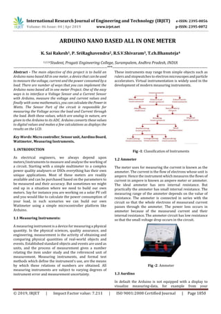
  • 1. International Research Journal of Engineering and Technology (IRJET) e-ISSN: 2395-0056 Volume: 06 Issue: 04 | Apr 2019 www.irjet.net p-ISSN: 2395-0072 © 2019, IRJET | Impact Factor value: 7.211 | ISO 9001:2008 Certified Journal | Page 1850 ARDUINO NANO BASED ALL IN ONE METER K. Sai Rakesh1, P. SriRaghavendra2, R.S.V.Shivaram3, T.ch.Bhanuteja4 1,2,3,4Student, Pragati Engineering College, Surampalem, Andhra Pradesh, INDIA ---------------------------------------------------------------------***---------------------------------------------------------------------- Abstract - The main objective of this project is to build an Arduino nano based All in one meter, a device that canbeused to measure the voltage, current and the power consumed by a load. There are number of ways that you can implement the Arduino nano based all in one meter Project. One of the easy ways is to interface a Voltage Sensor and a Current Sensor with Arduino, measure the voltage and current values and finally with some mathematics, you can calculatethePower in Watts. The Sensor Part of the circuit is responsible for measuring the Voltage across the load and Current through the load. Both these values, which are analog in nature, are given to the Arduino to its ADC. Arduino converts these values to digital values and makes a few calculations as displays the results on the LCD. Key Words: Microcontroller,Sensorunit,AurdinoBoard, Wattmeter, Measuring Instruments. 1. INTRODUCTION As electrical engineers, we always depend upon meters/instruments to measure and analyse the working of a circuit. Starting with a simple multimeter to a complex power quality analysers or DSOs everything has their own unique applications. Most of these meters are readily available and can be purchased based on the parameters to be measured and their accuracy. But sometimes we might end up in a situation where we need to build our own meters. Say for instance you are working on a solar PV cell and you would like to calculate the power consumption of your load, in such scenarios we can build our own Wattmeter using a simple microcontroller platform like Arduino. 1.1 Measuring Instruments: A measuring instrument is a device for measuring a physical quantity. In the physical sciences, quality assurance, and engineering, measurement is the activity of obtaining and comparing physical quantities of real-world objects and events. Established standard objects and events are used as units, and the process of measurement gives a number relating the item under study and the referenced unit of measurement. Measuring instruments, and formal test methods which define the instrument's use, are the means by which these relations of numbers are obtained. All measuring instruments are subject to varying degrees of instrument error and measurement uncertainty. These instruments may range from simple objects such as rulers and stopwatches to electron microscopesandparticle accelerators. Virtual instrumentation is widely used in the development of modern measuring instruments. Fig -1: Classification of Instruments 1.2 Ammeter The meter uses for measuring the current is known as the ammeter. The current is the flow of electrons whose unit is ampere. Hence the instrument which measures the flows of current in ampere is known as ampere meter or ammeter. The ideal ammeter has zero internal resistance. But practically the ammeter has small internal resistance. The measuring range of the ammeter depends on the value of resistance. The ammeter is connected in series with the circuit so that the whole electrons of measurand current passes through the ammeter. The power loss occurs in ammeter because of the measurand current and their internal resistance. The ammeter circuit has low resistance so that the small voltage drop occurs in the circuit. Fig -2: Ammeter 1.3 Aurdino In default the Arduino is not equipped with a display to visualize measuring-data, for example from your
  • 2. International Research Journal of Engineering and Technology (IRJET) e-ISSN: 2395-0056 Volume: 06 Issue: 04 | Apr 2019 www.irjet.net p-ISSN: 2395-0072 © 2019, IRJET | Impact Factor value: 7.211 | ISO 9001:2008 Certified Journal | Page 1851 temperature or your pressure Sensor. If you want to get the data shown you need a PC, printing the data totheconsole or mounting a display directly to the Arduino. So there is no simple way to WIRELESSLY visualizemeasuring-data.Inthis intractableFig.2will showhowto transfer measuredSensor- data in real-time from your Arduino-Microcontroller to your Android-Smartphone via Bluetooth. Fig -3: Bluetooth HC-05 and Arduino 2. PROBLEM FORMULATION It is difficult or sometimes even impossible to measure current, voltage and power at a time with ordinary multimeters and watt meters. It is very expensive to measure low power ratings with normal wattmeter and multimeter To overcome these disadvantages we are going to design a special type of meter with Arduino nano microcontroller with the help of the Arduino Microcontroller we can measure voltage current and power at a time. 2.1 Existing Technology The entire project can be divided into three basic blocks; 1) Power Sensor Unit 2) Processor Unit 3) Display Unit The Power Sensor Unit allows the current to flow through a device whose power consumption needs to be measured. The Sensor Unit produces two voltages, one is the Voltage output from the power supply and another one is a voltage which ranges from 0 to 5V. The difference between these two voltages is proportional to the amount of Current flowing through the Sensor unit. The ProcessorUnitcantake two input voltages both in the range of 0 to 5V. This unit takes the Sensor Unit’s output as input voltages and usesthe ADC to read these voltages. An Algorithm is then applied to calculate the Power consumptionofthedevice.Theunitthen sends a 4bit data to the Display Unit to display the power consumption in Watts. The Display Unit takes the 4bit data from the Processor Unit and produces a 16*2 display for the current consumption of the device. Fig -4: Block diagram 2.2 Proposed Technology The circuit is designed to fit into systems operatingbetween 0-24V with a current range of 0-1A keeping in mind the specification of small applications. But you can easilyextend the range once you understand the working of the circuit. The underlying principle behind the circuitistomeasurethe voltage across the load and current through it to calculate the power consumes by it. All the measured values will be displayed in a 16*2 Alphanumeric LCD. For ease of understanding the arduino wattmetercircuitissplitinto two units. The upper part of the circuit is the measuring unit and the lower part of the circuit is the computation and display unit. 3. Hardware Implementation The measuring unit consists of a potential divider to help us measure the voltage and a shut resistorwitha Non-Inverting Op-amp is used to help us measure the current through the circuit. The output voltage of a potential divider can be calculated using the below formulae. The same be used to decide the value of your resistors, you can use our online calculator to calculate value of resistor if you are re- designing the circuit. Next we have to measure the current through the LOAD. As we know microcontrollers can read only analog voltage, so we need to somehow convert the value of current to voltage. It can be done by simply addinga resistor (shunt resistor) in the path which according to Ohm’s law will drop a value of voltage across it that is proportional to the current flowing through it. The value of this voltage drop will be very less so we use an op-amp to amplify it. The circuit for the same is shown below. Here in our case the value of Rf is 20k and the value of Rin is 1k which gives us a gian value of 21. The amplified voltageform the Op-amp is then given to a RC filter with resistor 1k and a capacitor 0.1uF to filter any noise that is coupled. Finally the voltage is then fed to the Arduino analog pin.
  • 3. International Research Journal of Engineering and Technology (IRJET) e-ISSN: 2395-0056 Volume: 06 Issue: 04 | Apr 2019 www.irjet.net p-ISSN: 2395-0072 © 2019, IRJET | Impact Factor value: 7.211 | ISO 9001:2008 Certified Journal | Page 1852 Fig -5: Schematic diagram 4.1 Working The Arduino Nano has a number of facilities for communicating with a computer, another Arduino, or other microcontrollers. The ATmega328 provide UART TTL (5V) serial communication, which is available on digital pins 0 (RX) and 1 (TX). An FTDI FT232RL on the board channels this serial communication over USB and the FTDI drivers (included with the Arduino software) provide a virtual com port to software on the computer. The Arduino software includes a serial monitor which allows simpletextual data to be sent to and from the Arduino board. The RX and TX LEDs on the board will flash when data is being transmitted via the FTDI chip and USB connection to the computer (but not for serial communication on pins 0 and 1). A SoftwareSerial library allows for serial communication on any oftheNano's digital pins. Fig -6: Arduino nano 4.2 Results This kit explains about the project “Arduino Nano All in One Meter” .In this project when supply is givenarduinoandLCD are powered up. Power supply is adjusted to 24v with the help of RPS. When the load is connected voltage, currentand power values are displayed on the LCD. Fig -7: Arduino nano all in one meter 5. CONCLUSION This is a project based on Arduino board which can measures the voltage, currentandpowerconsumptionofthe devices at a time. When we connect this wattmeter on to a device which is in operation, the 16*2 LCD displays its voltage value in volts, current value in amperes and power consumption value in Watts. The project uses an Arduino pro mini board whose ADC feature is used along with the concept of Ohm’s law and Voltage Divider circuit to develop this Wattmeter. This project is cost friendly and have less complexity. This project gives more accurate results for the parameters. 6. FUTURE SCOPE This Arduino based all in one meter project has many more upgrades that can be added to increase the performance to auto data logging, plotting graph, notifying over voltage or over current situations etc. Also we can add other parameters like energy , power factor etc by changing the source code. By changing the component ratings in the circuit we can measure high loads. REFERENCES 1) HernandoBarragán(2016-01-01). "TheUntoldHistoryof Arduino" 2) “Programming Arduino”, book by “Simon Monk” 3) https://circuitdigest.com/microcontroller- projects/arduino-wattmeter-to-measure-voltage- current-power-consumption 4) https://meettechniek.info/diy-instruments/arduino- wattmeter.html 5) https://www.electronicshub.org/arduino-wattmeter/