"Just Enough" System Modeling
24 likes36,782 views

This document outlines an agenda for a seminar on methodological and effective system modeling with UML/SysML. The seminar will introduce principles of effective system modeling and useful modeling elements in UML and SysML. It will demonstrate applying a methodological modeling approach to computer embedded systems using a case study. The agenda includes topics such as modeling in systems engineering, modeling systems and blocks, modeling different views of a block, modeling in the system development life cycle, and modeling computer embedded systems.


![What is “Modeling” about?
• In engineering, Modeling is used as a method for laying out a specification
of an entity to be implemented
– Implementing an entity without prior specification is often considered as
“art”
• History shows, that the first project on earth was first implemented, then
specified
And God said, let there be light: and there was light... And God called the light Day, and the
darkness he called Night...
[Genesis 1,3-5]
• However, not long later, the first detailed engineering specification was
carefully written by the same Systems Engineer…
And God said unto Noah... Make thee an ark of gopher wood; rooms shalt thou make in the ark, and
shalt pitch it within and without with pitch. And this is the fashion which thou shalt make it of: The
length of the ark shall be three hundred cubits, the breadth of it fifty cubits and the height of it thirty
cubits. A window shalt thou make to the ark, and in a cubit shalt thou finish it above; and the door
of the ark shalt thou set in the side thereof; with lower, second, and third stories...
[Genesis 6,13-16]
© 2010-2011, Dr. Amir Tomer 6 Effective MBD with SysML/UML](https://image.slidesharecdn.com/mbd-methodology-ver-2-eng-141121111719-conversion-gate02/85/Just-Enough-System-Modeling-6-320.jpg)


![System Modeling Methodology
• Methodology
– A body of methods, rules, and postulates employed by a discipline : a
particular procedure or set of procedures [Merriam-Webster Dictionary]
• Modeling Methodology
– Methods, rules and postulates for applying a modeling language in a
particular domain
• System Modeling Methodology
– A modeling methodology used in analysis and design of systems
© 2010-2011, Dr. Amir Tomer 15 Effective MBD with SysML/UML](https://image.slidesharecdn.com/mbd-methodology-ver-2-eng-141121111719-conversion-gate02/85/Just-Enough-System-Modeling-15-320.jpg)


![“Block” – a unified notion
• In order to obtain unified modeling concepts for systems and elements at all
levels
– i.e. System-of-system, system, subsystem, assembly, component, unit, etc.
we define a unified entity, noted as “Block”, as follows:
1. A system is a block
2. A system is composed of one or more blocks
3. An element (system element) is a block, which is atomic (non-decomposable)
4. Every block has one or more purposes
5. A system has an organization (over its blocks)
6. A system has an interaction (among its blocks)
4
Element
Legend
inheritance relation
composition relation
+ P public property
- P private property
Based on the “composition” design pattern: Vlissingen et al, Design Patterns, 1994
1
2
+ Purpose [1...*]
3
<<abstract>>
Block
5
6
1..*
System
- organization
- interaction
© 2010-2011, Dr. Amir Tomer 20 Effective MBD with SysML/UML](https://image.slidesharecdn.com/mbd-methodology-ver-2-eng-141121111719-conversion-gate02/85/Just-Enough-System-Modeling-20-320.jpg)


![Surround Consistency [non-atomic blocks only]
• The connection of the internal structure
with the external environment is
obtained through the external interfaces
of their containing block
• Surround consistency is achieved when
– Each connection of an internal element to
the external environment is obtained
through one or more identified external
interfaces
– Each external interface of the block
connects the external environment with
one or more internal elements
Pedal interface to the break system
Static Dynamic
Interfaces Services
Structure Behavior
External
Internal
© 2010-2011, Dr. Amir Tomer 27 Effective MBD with SysML/UML](https://image.slidesharecdn.com/mbd-methodology-ver-2-eng-141121111719-conversion-gate02/85/Just-Enough-System-Modeling-27-320.jpg)


![Structure Modeling in UML (3)
Class diagram
Elevator
+ ID: {A,B,C}
- stop_list: Floor[0..*]
+ request({up,down}, Floor) : void
Motor
+ move({up,down}) : void
+ stop() : void
Door
+ open() : void
+ close() : void
FloorButton StopButton
Technician
Floor
service
+ label: {0,1,...,n}
Button
- isLit: boolean
+ push() : void
1..*
represents
1..*
• Class Diagrams
– UML’s class diagrams were originally designed for
Object Oriented Design (software), but can be
effectively used for conceptual structures at all block
levels
– The basic constructs of a class diagram are
• Classes: Conceptual entities containing attributes and
functions
– Serve as descriptors of specific “real” objects
• Associations (): Relations among classes
• Inheritance (): Attribute/function sharing among
variations of sub-classes derived from a super-class
• Aggregation: Containment of objects within the
structure of another object
– Composition (): The sub-block is “owned” by the
block (whole-part relation)
– Shared aggregation (): The sub-block is associated
with the block, but has independent existence and
may be shared by other blocks
© 2010-2011, Dr. Amir Tomer 42 Effective MBD with SysML/UML](https://image.slidesharecdn.com/mbd-methodology-ver-2-eng-141121111719-conversion-gate02/85/Just-Enough-System-Modeling-42-320.jpg)


![Flow Modeling with Activity Diagrams
• UML’s Activity Diagram is best used to describe
a pre-determined behavior with internal control
– SysML’s EFFBD (Enhanced Functional Flow
Block Diagram) is an enhanced form of this
model
• Activity diagram comprises the following
constructs
– Activities/Actions: Depicted by rounded
blocks
– Control flows: Depicted by arrows
– Conditional nodes
• Decision: Directing the flow to one of a number
of possible directions, based upon a guard
(condition)
• Merge: Directing flows coming from any
direction to a single direction
• Fork: Distributing the flow into a number of
concurrent (parallel) flows
• Join: Directs a number of concurrent flows into
a single flow
Read
parking card
Eject card
[card valid]
Calculate
fee
Display fee
Accept cash
[cash<fee]
Print ticket
Dispense
change
© 2010-2011, Dr. Amir Tomer 47 Effective MBD with SysML/UML](https://image.slidesharecdn.com/mbd-methodology-ver-2-eng-141121111719-conversion-gate02/85/Just-Enough-System-Modeling-47-320.jpg)
![Activity Diagrams with Data Flow
• Activity Diagrams can model data flow
besides the control flow
– Data item
• A single unit of information generated
by an activity and consumed by
another activity
– Data store
• Collection of data units stored by
activities and retrieved by other
activities
(Remember the good old DFD?)
Read
parking card
Eject card
[card valid]
Calculate
fee
Display fee
Accept cash
[cash<fee]
Print ticket
<<datastore>>
Dispense
change
fee
cashbox
© 2010-2011, Dr. Amir Tomer 48 Effective MBD with SysML/UML](https://image.slidesharecdn.com/mbd-methodology-ver-2-eng-141121111719-conversion-gate02/85/Just-Enough-System-Modeling-48-320.jpg)
![Activity Diagrams with Swim Lanes
Card Reader Printer Processor Cash Box Display
Read
parking card
Eject card
• Swim lanes are
partitions within an
activity diagram
which represent
the allocation of
activities to sub-block
[card valid]
Calculate
fee
Display fee
Accept cash
Print ticket
Dispense
change
[cash<fee]
© 2010-2011, Dr. Amir Tomer 49 Effective MBD with SysML/UML](https://image.slidesharecdn.com/mbd-methodology-ver-2-eng-141121111719-conversion-gate02/85/Just-Enough-System-Modeling-49-320.jpg)
![File-received
/ notify
Busy
Modeling Event-Driven flow with State Machine
• UML’s State Machine Diagram* is used to model
the behavior of an entity that is driven by external
or internal events
• State Machine Diagram comprises the following
structures:
– State: A period of time during which the entity is
actively or passively “busy” in some specified task
– Transition: An arrow indicating possible transfer
from one state to another
• Transitions are labeled by events
– Event: A trigger that causes the entity to perform
a state transition
– Guard: A condition that limits the transition upon
event to occur
– Action: An activity which is performed upon a
transition or upon entering a state, exiting a state
or while being in a state
*Originated from David Harel’s mathematical model (1987)
idle
Printing
cancel
End-of-file
Do/ loop
{print page, eject page}
Stuck paper
/ notify
Feeder_empty
/ notify
Feeder_full
Jammed Out of paper
Cover_opened Cover_closed
Repairing
[stuck paper]
Cover_closed [clear]
© 2010-2011, Dr. Amir Tomer 50 Effective MBD with SysML/UML](https://image.slidesharecdn.com/mbd-methodology-ver-2-eng-141121111719-conversion-gate02/85/Just-Enough-System-Modeling-50-320.jpg)
![Modeling Interactive Flow with Sequence Diagram
• Sequence Diagram is UML’s most popular model for interactive behavior within the
elements of a block structure and between them and the outside environment
• Sequence Diagram comprises the
following constructs:
– Participants: May be external
(actors) or internal (sub-blocks)
– Each participant has a life-line
and activity lines
– Messages: transfer of control
from one participant to
another (function calls)
• Synchronous: The sender
awaiting “return”
• Asynchronous: “Fire &
forget”
– Interaction Frames: Control
logic (e.g. loops, conditionals,
parallel)
Visitor
Gate Computer
Security
read_card()
alt Authorized?
[yes]
[no]
identify() :ID
grant_access(ID) :Authorization
check(ID) :
Authoriztion
:Authorization
open()
intrusion_alert(ID)
© 2010-2011, Dr. Amir Tomer 51 Effective MBD with SysML/UML](https://image.slidesharecdn.com/mbd-methodology-ver-2-eng-141121111719-conversion-gate02/85/Just-Enough-System-Modeling-51-320.jpg)


![The CSCI Level
• A CSCI is an aggregation of software that satisfies an end use function… [MIL-STD-498]
– E.g. The cellphone’s phone-call software
View Content Examples
Services
(purposes)
End use functions placing calls, receiving calls, sending SMS
Interfaces Commands, data and signals
via hardware ports
Receive/Transmit messages, touch screen
Structure Elements
Software Components (CSCs)
Organization
SW-SW communication
Rx/Tx drivers, GUI, DLLs, …
message passing, internal mailboxes
Behavior Algorithms/Procedures Dial-send-connect-talk-hangup
CSCI
CSCs
HW Devices Other CICs
© 2010-2011, Dr. Amir Tomer 79 Effective MBD with SysML/UML](https://image.slidesharecdn.com/mbd-methodology-ver-2-eng-141121111719-conversion-gate02/85/Just-Enough-System-Modeling-79-320.jpg)


![UnderMiner: Business Level – Behavior(1)
• Modeling the Business Logic with Activity Diagram can provide clear and
consistent transition from Business Level Use Cases to System Level Use Cases
Business Behavior
«structured»
Operation Initiation
Command
Transfer
Operation
Planning
[rejected]
plan
approval
[approved]
Mission
Allocation
«structured»
Operation Execution
Operation
Plan
«datastore»
Mission Table
Operation
Command
Mission Execution
(scan/trap/clear)
1..8
Preparation for
Mission
Mission
Terminated
[change]
[completion]
[trouble]
[no] [yes]
Self Destruction?
Mole
Shutdown
Mole
Destruction
[continue]
Commander
Decision
Operation
Termination
Operation
Initiation
Status
Demand
«datastore»
Collected Data
«structured»
[destroy]
Operation Monitoring
«loop»
Periodic Report
Status Report
Report Type
Operation
Status
0..8
[periodic]
[on demand]
Business Services
UnderMiner unit
Headquarters
Operation
Initiation
Operation
Monitoring
«include»
Operation
Execution
UM commander
Mole operator
SIS Services (Ucs)
© 2010-2011, Dr. Amir Tomer 89 Effective MBD with SysML/UML](https://image.slidesharecdn.com/mbd-methodology-ver-2-eng-141121111719-conversion-gate02/85/Just-Enough-System-Modeling-89-320.jpg)
![UnderMiner: Business Level – Behavior(2)
«structured»
Operation Initiation
Command
Transfer
Operation
Planning
Preparation for
Mission
[rejected]
plan
approval
[approved]
Mission
Allocation
Operation
Plan
«datastore»
Mission Table
Operation
Initiation
Operation
Command
© 2010-2011, Dr. Amir Tomer 90 Effective MBD with SysML/UML](https://image.slidesharecdn.com/mbd-methodology-ver-2-eng-141121111719-conversion-gate02/85/Just-Enough-System-Modeling-90-320.jpg)
![UnderMiner: Business Level – Behavior(3)
«structured»
Operation Execution
«datastore»
Mission Table
Mission Execution
(scan/trap/clear)
1..8
Preparation for
Mission
Mission
Terminated
[change]
[completion]
[trouble]
[no] [yes]
Self Destruction?
Mole
Shutdown
Mole
Destruction
[continue]
Commander
Decision
Operation
Termination
Status
Demand
«datastore»
Collected Data
«structured»
[destroy]
Operation Monitoring
«loop»
Periodic Report
Status Report
Report Type
Operation
Status
0..8
[periodic]
[on demand]
© 2010-2011, Dr. Amir Tomer 91 Effective MBD with SysML/UML](https://image.slidesharecdn.com/mbd-methodology-ver-2-eng-141121111719-conversion-gate02/85/Just-Enough-System-Modeling-91-320.jpg)

![UnderMiner: SIS Level – Services (2): UC Specification
SUC-3 Mission Allocation
Actors & Goals UM Commander: Allocate Missions to Mole Operators
Mole Operators [1..8]: Supporting Actors
Stakeholders &
interests
Headquarters: Mission is understood and executable
pre-conditions Approved mission plan exists in the system [assured by SUC-2]
post-conditions Mole mission table exists
Each mole’s mission is approved by its operator
trigger UM Commander operates “mission allocation” on his workstation
MSS 1. UM Commander generates/updates the mole mission table
2. The System stores the mission table
3. The System notifies the operator about allocated/changed missions
4. Each Operator retrieves its mole’s mission from the mission table
5. Each Operator verifies that the mission is understood and approves it
6. The System records the approval at the mission table
7. UM Commander verifies that all operators approved their missions
Branch A Alternative at step 5 of MSS:
5A1. The Operator applies to the UM Commander to check the mission
together
5A2. The Operator updates the mission table as necessary
5A3. Back to step 2
© 2010-2011, Dr. Amir Tomer 93 Effective MBD with SysML/UML](https://image.slidesharecdn.com/mbd-methodology-ver-2-eng-141121111719-conversion-gate02/85/Just-Enough-System-Modeling-93-320.jpg)


![UnderMiner: SIS Level – Behavior
(Realization of the “Perform Scanning” Use Case )
Mole
C4I
"GO"
command
transfer
Mov ing in
Tunnel
Sensor
sampling
Image & track
transmission
Switch to
manual
Destruction
Indication to
commander
and operator
Tunnel map
generarion
Map display
to operator
Track display
to commander
stop?
[yes]
[no]
Comm. resumed?
[mole stuck]
[end of
route]
Back to
entrance
success?
«datastore»
Images & Tracks
Image Track
[no]
[yes]
Stop & wait
for comm.
resume
[yes]
[no]
[trouble]
[mole clash]
[stopped by
operator]
As the system is
composed only of 2
elements (C4I,
Mole) an Activity
Diagram with swim-lanes
was preferred
here over Sequence
Diagram
© 2010-2011, Dr. Amir Tomer 96 Effective MBD with SysML/UML](https://image.slidesharecdn.com/mbd-methodology-ver-2-eng-141121111719-conversion-gate02/85/Just-Enough-System-Modeling-96-320.jpg)


![UnderMiner/C4I SW: CSCI Level – Behavior
(Realization of the “Performing Clearing” Use Case)
Mole operator
«GUI»
C4I SW::Operator HMI
Mole SW::Mission
Management
«driver»
Mole SW::Shooting
C&C
Shooting Mechanism
Start Clearing Mission()
alt Halt Reason
[Trouble]
[End of Tunnel]
*[to end of tunnel]:Ongoing Shooting()
ref
Motion in Tunnel
ref
Mole Destruction
Start_Clearing( )
Start Shooting()
Start Motion()
Trouble()
Stop Shooting()
Back to Entrance()
Data
Services
Command &
Takeover Maps &
Sensor Command & Input
Upper
Command
«driver»
Sense C&C
{1..8}
Sensor
Sampl ing
Sensor
C&C
Motion operation
Preparation
for Mission
Mole
Startup
Mole
«include»
Shutdown
© 2010-2011, Dr. Amir Tomer 101 Effective MBD with SysML/UML
Motion Mech
C&C
«driver»
Motion C&C Shooting Mech
C&C
«driver»
Shooting C&C Destruction
Mech C&C
«driver»
Destruction C&C Mining Mech
C&C
«driver»
Mining C&C Navigation &
Manual Maneuvering
Maneuvering
Mission
Mole Management
C&C
Sensor
Sampl ing
Destruction
Operation
Mining
Operation
Shooting
Operation
Navigation &
Maneuvering
Operation
Mole
Performing
Scanning
Performing Mole operator
Trapping
Ferforming
Clearing
Mole
Destruction
«extend»
«extend»
«extend»
«GUI»
Commander HMI
Commanded
C&C
Manual
Maneuvering
Mole
Operation
«GUI»
Operator HMI
Operator
C&C
Headquarters
Interface
Data
Management
Sensor
Sampling
Image
Processing
C&C
Data
Services
Tunnel Mapping
Tracks
Data
Services](https://image.slidesharecdn.com/mbd-methodology-ver-2-eng-141121111719-conversion-gate02/85/Just-Enough-System-Modeling-101-320.jpg)
![UnderMiner/Mole SW/Sense C&C: CSC Level – Services
Sense C&C (CSC)
Continuous
Scanning
Continuous
Scanning
Initiation
Mission Sensor Array
Continuous
Scanning
Termination
Data Request
Management
(CSC)
(Any Sample
Consumer)
C4I SW::Image
Processing
«driver» 1..8
Mole SW::Sense C&C
«GUI»
C4I SW::Operator HMI
Start Continuous Display()
loop
[As long as the mole is active]
Read Sensor Sample()
:Sensor Sample
Update Tunnel Map()
Transmit Updated Map()
Update Tunnel
Display()
© 2010-2011, Dr. Amir Tomer 102 Effective MBD with SysML/UML](https://image.slidesharecdn.com/mbd-methodology-ver-2-eng-141121111719-conversion-gate02/85/Just-Enough-System-Modeling-102-320.jpg)

![UnderMiner/Mole SW/Sense C&C: CSC Level – Structure
SnapShot
+ timeTag: time
- sampleVector: surfacePoint [1..*]
+ collectSampleData() : void
provide 0..*
1
SensorArray
- isActive: boolean
+ startScanning() : void
+ stopScanning() : void
+ storeSnapShot() : void
+ getLatestSample() : SnapShot
+ retrieveSnapShot() : SnapShot
surfacePoint
+ Phi: float
+ Theta: float
+ Radius: float
+ Rigidity: float
Sensor
+ sensorID: int
+ Phi: float
+ Theta: float
- isActive: boolean
+ lastRadius: float
+ lastRigidity: float
report
+ getLastSurfacePoint() : surfacePoint
+ getStatus() : byte
sampleConsumerIF
- dataMessage: bitstream
1 1..*
+ dataRequest(C :channel) : void
- sendData(C :channel) : void
+ appendSnapShot(Msg :bitstream*, Snp :SnapShot) : void
© 2010-2011, Dr. Amir Tomer 104 Effective MBD with SysML/UML](https://image.slidesharecdn.com/mbd-methodology-ver-2-eng-141121111719-conversion-gate02/85/Just-Enough-System-Modeling-104-320.jpg)
![UnderMiner/Mole SW/Sense C&C: CSC Level – Behavior
:sampleConsumerIF :SensorArray S :SnapShot
dataRequest(myChannel)
loop
[while snapshots exist]
dataMessage= EMPTY()
S= getLatestSample()
retrieveSnapShot()
appendSnapShot(dataMessage,S)
sendData(myChannel)
SnapShot
+ timeTag: time
- sampleVector: surfacePoint [1..*]
+ collectSampleData() : void
provide 0..*
1
SensorArray
- isActive: boolean
+ startScanning() : void
+ stopScanning() : void
+ storeSnapShot() : void
+ getLatestSample() : SnapShot
+ retrieveSnapShot() : SnapShot
surfacePoint
+ Phi: float
+ Theta: float
+ Radius: float
+ Rigidity: float
Sensor
+ sensorID: int
+ Phi: float
+ Theta: float
- isActive: boolean
+ lastRadius: float
+ lastRigidity: float
report
+ getLastSurfacePoint() : surfacePoint
+ getStatus() : byte
sampleConsumerIF
- dataMessage: bitstream
1 1..*
+ dataRequest(C :channel) : void
- sendData(C :channel) : void
+ appendSnapShot(Msg :bitstream*, Snp :SnapShot) : void
Sense C&C (CSC)
Continuous
Scanning
Continuous
Scanning
Initiation
Mission Sensor Array
Continuous
Scanning
Termination
Data Request
Management
(CSC)
(Any Sample
Consumer)
© 2010-2011, Dr. Amir Tomer 105 Effective MBD with SysML/UML](https://image.slidesharecdn.com/mbd-methodology-ver-2-eng-141121111719-conversion-gate02/85/Just-Enough-System-Modeling-105-320.jpg)
![UnderMiner/Mole SW/Sense C&C/sampleConsumerIF: CSU Level –
Structure + Behavior (in code)
sampleConsumerIF
- dataMessage: bitstream
+ dataRequest(C :channel) : void
- sendData(C :channel) : void
+ appendSnapShot(Msg :bitstream*, Snp :SnapShot) : void
public class sampleConsumerIF {
private bitstream dataMessage;
public sampleConsumerIF(){
}
public void dataRequest(channel C){
To be programmed …
}
private void sendData(channel C){
}
public void appendSnapShot(bitstream Msg, SnapShot Snp){
}
}
:sampleConsumerIF :SensorArray S :SnapShot
dataRequest(myChannel)
loop
[while snapshots exist]
dataMessage= EMPTY()
S= getLatestSample()
retrieveSnapShot()
appendSnapShot(dataMessage,S)
sendData(myChannel)
© 2010-2011, Dr. Amir Tomer 106 Effective MBD with SysML/UML](https://image.slidesharecdn.com/mbd-methodology-ver-2-eng-141121111719-conversion-gate02/85/Just-Enough-System-Modeling-106-320.jpg)


"Just Enough" System Modeling
- 1. Methodological and Effective System Modeling With UML/SysML Dr. Amir Tomer Software Engineering Department Head [email protected] 052-8890202 © 2010-2011, Dr. Amir Tomer 1 Effective MBD with SysML/UML
- 2. The Rationale for this Seminar Methodology: The link between Process and Language Available Processes • ISO/IEC/IEEE 15288 • IEEE-Std-1220 • INCOSE SE Handbook • CMMI for Development • … Available Languages • UML • SysML • Simulink • OPM • … Available Methodologies • Rational Unified Process (RUP) • DODAF/ MODAF • SYSMOD • … © 2010-2011, Dr. Amir Tomer 2 Effective MBD with SysML/UML
- 3. Seminar Objectives • Introducing principles of effective system modeling • Introducing a selection of useful UML/SysML modeling elements • Embracing the modeling languages under methodology and effectiveness considerations • Applying a methodological modeling to Computer Embedded Systems • Demonstrating an overall modeling framework of a “real life” system © 2010-2011, Dr. Amir Tomer 3 Effective MBD with SysML/UML
- 4. Agenda • Modeling in Systems Engineering • Systems and Blocks • Modeling the Block’s Different Views • Modeling in the System Development Life Cycle • Modeling the Entire System’s Life Cycle • Modeling Computer Embedded Systems • A Case-Study of System Modeling • Conclusions and Wrap-up © 2010-2011, Dr. Amir Tomer 4 Effective MBD with SysML/UML
- 5. Agenda Modeling in Systems Engineering • Systems and Blocks • Modeling the Block’s Different Views • Modeling in the System Development Life Cycle • Modeling the Entire System’s Life Cycle • Modeling Computer Embedded Systems • A Case-Study of System Modeling • Conclusions and Wrap-up © 2010-2011, Dr. Amir Tomer 5 Effective MBD with SysML/UML
- 6. What is “Modeling” about? • In engineering, Modeling is used as a method for laying out a specification of an entity to be implemented – Implementing an entity without prior specification is often considered as “art” • History shows, that the first project on earth was first implemented, then specified And God said, let there be light: and there was light... And God called the light Day, and the darkness he called Night... [Genesis 1,3-5] • However, not long later, the first detailed engineering specification was carefully written by the same Systems Engineer… And God said unto Noah... Make thee an ark of gopher wood; rooms shalt thou make in the ark, and shalt pitch it within and without with pitch. And this is the fashion which thou shalt make it of: The length of the ark shall be three hundred cubits, the breadth of it fifty cubits and the height of it thirty cubits. A window shalt thou make to the ark, and in a cubit shalt thou finish it above; and the door of the ark shalt thou set in the side thereof; with lower, second, and third stories... [Genesis 6,13-16] © 2010-2011, Dr. Amir Tomer 6 Effective MBD with SysML/UML
- 7. The Concept of “Modeling” • What is Modeling? – A means to capture ideas, relationships, decisions and requirements in a well-defined notation that can be applied to many different domains [Pilone, D., UML 2.0 in a Nutshell, O’REILLY®, 2005 • Models are used for simplified (abstract) description of complex entities – Models focus on principle elements, leaving out unnecessary details – Models need to be “translated” into the real world – A model leaves degrees of freedom to different interpretations © 2010-2011, Dr. Amir Tomer 7 Effective MBD with SysML/UML
- 8. Static and Dynamic Models • Static / Structural Model – A model describing entities with relations among them • Organizational chart • Mechanical drawing • Molecular structure • Database table • Dynamic / Behavioral Model – A model describing flow / changes along time • Flowchart • Graphical representation of a time function • Automaton (in Computer Science) • Animation / Simulation • A model may be visual, textual or combined © 2010-2011, Dr. Amir Tomer 8 Effective MBD with SysML/UML
- 9. The Importance of System Modeling • Modeling has long been used in specific engineering disciplines – Electrical drawings in EE – Mechanical drawings and models in ME – Construction models in BE • Why modeling is poorly employed in Systems Engineering? – No clear engineering discipline? – Multiple domains/technologies? – Too complex to model effectively? • The following cannot be considered effective system models – A PowerPoint presentation with a couple of block diagrams – RFP/Proposal – A requirements table/DB – A ConOp document – A look&feel demo • Why does Systems Engineering need modeling? – A reverse question: Can it be done effectively without it? © 2010-2011, Dr. Amir Tomer 9 Effective MBD with SysML/UML
- 10. The Use of Modeling • Modeling is useful in two directions – Forward Modeling: Modeling before implementation • Sketching new ideas • Brainstorming about solutions • Evaluating solution alternatives • Directing the development – Reverse Modeling: Modeling after implementation • Documenting the system “as built” • Explaining the system to others • Supporting system production / maintenance / upgrading • Reusing as forward modeling in future projects © 2010-2011, Dr. Amir Tomer 10 Effective MBD with SysML/UML
- 11. Elements of a (Visual) Modeling Language • Alphabet: A set of “legal” symbols {text} • Syntax: Rules for forming “legal” combination of elements • Semantics: The meaning of syntactical combinations ? B A x “A transfers x to B” “A activates B by signaling x” • Expressiveness: What can/cannot be expressed by the language “A transfers x to B” “A can transfer x to B only if B is in ‘receiving’ mode” © 2010-2011, Dr. Amir Tomer 11 Effective MBD with SysML/UML
- 12. Popular Static Modeling Language: Block Diagrams • Advantages – Easy to draw – Simple and intuitive to understand – General purpose • Disadvantages – Poor expressiveness – need additional explanations – Too general – lead to misinterpretations © 2010-2011, Dr. Amir Tomer 12 Effective MBD with SysML/UML
- 13. Popular Dynamic Modeling Language: Flow Charts • Advantages – Easy to draw – Well known • Disadvantages – Limited expressiveness – e.g. impossible to describe parallel flows © 2010-2011, Dr. Amir Tomer 13 Effective MBD with SysML/UML
- 14. UML/SysML – Unified/System Modeling Language • UML and SysML provide a set of models, based on a visual language, that can be effectively applied to model software and systems – The following structure represents the diagrams (models) covered in SysML – UML has additional diagrams – two of them added here – Only the highlighted diagrams will be presented and used in this seminar Deployment Diagram Component Diagram UML only: © 2010-2011, Dr. Amir Tomer 14 Effective MBD with SysML/UML
- 15. System Modeling Methodology • Methodology – A body of methods, rules, and postulates employed by a discipline : a particular procedure or set of procedures [Merriam-Webster Dictionary] • Modeling Methodology – Methods, rules and postulates for applying a modeling language in a particular domain • System Modeling Methodology – A modeling methodology used in analysis and design of systems © 2010-2011, Dr. Amir Tomer 15 Effective MBD with SysML/UML
- 16. Properties of a good model • Fits to purpose – Provides a visible abstraction of the real entity • Self understood – Minimizes the needs for additional explanations • Self contained – Can be understood without relying on other models • Accurate – Uses the modeling language correctly • Simple – Contains the minimum set of necessary details • Consistent – Its parts are cohesive and well related to each other • Unambiguous – Can be understood in a single way © 2010-2011, Dr. Amir Tomer 16 Effective MBD with SysML/UML
- 17. Agenda • Modeling in Systems Engineering Systems and Blocks • Modeling the Block’s Different Views • Modeling in the System Development Life Cycle • Modeling the Entire System’s Life Cycle • Modeling Computer Embedded Systems • A Case-Study of System Modeling • Conclusions and Wrap-up © 2010-2011, Dr. Amir Tomer 17 Effective MBD with SysML/UML
- 18. “System” – a recursive-hierarchical Structure* hierarchy depends on the scope of interest) Recursion A system is comprised of systems (and elements) (The depth of the system element system element Hierarchy *ISO/IEC/IEEE 15288 system-of-interest system system element system element system element system element system system system system element system element system system element system element system element system system element system element system element system © 2010-2011, Dr. Amir Tomer 18 Effective MBD with SysML/UML
- 19. Properties of a System • System – Definition* – combination of interacting elements organized to achieve one or more stated purposes • Thus, each system has the following properties – Purpose(s) – Elements – Interaction (among its elements) – Organization (over its elements) • System Element – Definition* – member of a set of elements that constitutes a system • Thus, according to the recursive-hierarchical structure, a system element may be either – A system by itself – possessing all system properties – An elementary (atomic) entity – possessing just purpose(s) *ISO/IEC/IEEE 15288 © 2010-2011, Dr. Amir Tomer 19 Effective MBD with SysML/UML
- 20. “Block” – a unified notion • In order to obtain unified modeling concepts for systems and elements at all levels – i.e. System-of-system, system, subsystem, assembly, component, unit, etc. we define a unified entity, noted as “Block”, as follows: 1. A system is a block 2. A system is composed of one or more blocks 3. An element (system element) is a block, which is atomic (non-decomposable) 4. Every block has one or more purposes 5. A system has an organization (over its blocks) 6. A system has an interaction (among its blocks) 4 Element Legend inheritance relation composition relation + P public property - P private property Based on the “composition” design pattern: Vlissingen et al, Design Patterns, 1994 1 2 + Purpose [1...*] 3 <<abstract>> Block 5 6 1..* System - organization - interaction © 2010-2011, Dr. Amir Tomer 20 Effective MBD with SysML/UML
- 21. System in its Environment* Stakeholders Have no interaction but impose needs, constraints and interests Enabling System A Enabling System B Enabling Interaction with enabling System C systems, usually in other life-cycle stages rather than operation System B in Operational Environment System of Interest System A in Operational Environment System C in Operational Environment Interaction with systems comprising the operational environment Interaction with Users / Operators *ISO/IEC/IEEE 15288 © 2010-2011, Dr. Amir Tomer 21 Effective MBD with SysML/UML
- 22. The multiple views of a System / Block • Complex systems have multiple views, from multiple viewpoints – SysML provides means to model views and viewpoints, using the following definitions • Viewpoint: A specification of the conventions and rules for constructing and using a view for the purpose of addressing a set of stakeholder concerns • View: A representation of a whole system or subsystem from the perspective of a single viewpoint • In this seminar we are not using the SysML’s views and viewpoints formally Picture Source: Booch, G., Object-Oriented Analysis and Design, Benjamin/Cummings, 1994 © 2010-2011, Dr. Amir Tomer 22 Effective MBD with SysML/UML
- 23. Universal Block Viewpoints and Views Static Viewpoint Dynamic Viewpoint Interfaces The connection points between the block and its external entities Services (Functions) The provided/acquired services(functions) to/from external entities and the way these services are obtained Structure (non-atomic blocks only ) The elements comprising the block and their interrelations Behavior purpose Interaction The activities the block needs to perform in order to provide its services External Viewpoint (Black Box) Organization Internal Viewpoint (White Box) © 2010-2011, Dr. Amir Tomer 23 Effective MBD with SysML/UML
- 24. Views and Models • An overall model of a block should represent all its relevant views • Each view may be depicted by one or more models • Methodological considerations – One “all inclusive” language or view-dependent language? – Same language for all models of the same view? – Breadth-first / Depth-first modeling? • Consistency considerations – Consistency between views – Consistency between models in the same view – Consistency between the block’s model and the models of its sub-block’s © 2010-2011, Dr. Amir Tomer 24 Effective MBD with SysML/UML
- 25. Consistency between views • The various views of a block are inter-related – Services are provided/acquired over interfaces – The internal structure elements connect to the external environment through the interfaces – The behavior realizes the services – The behavior is obtained by the interaction between structure elements • The following slides discuss these consistencies in detail Static Dynamic Interfaces Services Structure Behavior External Internal © 2010-2011, Dr. Amir Tomer 25 Effective MBD with SysML/UML
- 26. Accessibility Consistency • External interfaces are the gateways through which – External entities access the block’s services – The block’s services acquire services/functions from external entities • Accessibility consistency is achieved when – Each external entity uses one or more interfaces to obtain / provide services – Each interface is used for service provision / acquisition by one or more identified stakeholders Driving interface Fueling interface Static Dynamic Interfaces Services Structure Behavior External Internal © 2010-2011, Dr. Amir Tomer 26 Effective MBD with SysML/UML
- 27. Surround Consistency [non-atomic blocks only] • The connection of the internal structure with the external environment is obtained through the external interfaces of their containing block • Surround consistency is achieved when – Each connection of an internal element to the external environment is obtained through one or more identified external interfaces – Each external interface of the block connects the external environment with one or more internal elements Pedal interface to the break system Static Dynamic Interfaces Services Structure Behavior External Internal © 2010-2011, Dr. Amir Tomer 27 Effective MBD with SysML/UML
- 28. Realization Consistency • The services of the block are realized by the internal behavior of its elements • Realization consistency exists when – Each service is realized by an identified internal behavior – Each internal behavior realizes the whole or part of one or more identified services Implementing the “Brake the Car” service Static Dynamic Interfaces Services Structure Behavior External Internal © 2010-2011, Dr. Amir Tomer 28 Effective MBD with SysML/UML
- 29. Operability Consistency • The behavior of a non-atomic block is obtained by interaction among the elements comprising its structure • Operability consistency exists when – Each behavior is achieved by interaction between identified elements – Each element interacts with one or more other elements as part of one or more identified behaviors Cooling system: interacting elements Static Dynamic Interfaces Services Structure Behavior External Internal © 2010-2011, Dr. Amir Tomer 29 Effective MBD with SysML/UML
- 30. Agenda • Modeling in Systems Engineering • Systems and Blocks Modeling the Block’s Different Views • Modeling in the System Development Life Cycle • Modeling the Entire System’s Life Cycle • Modeling Computer Embedded Systems • A Case-Study of System Modeling • Conclusions and Wrap-up © 2010-2011, Dr. Amir Tomer 30 Effective MBD with SysML/UML
- 31. Modeling the Services • The purpose of a block is to provide services (functions) to its external environment – When a block has no sufficient capability to provide its services based on its own means it may acquire services (functions) from the external environment • Services are provided / acquired by means of interaction with external entities, called Actors – Examples • Systems in the operational environment • Enabling systems • Other blocks within a given structure • Devices (e.g. sensors, actuators, …) • Human users / operators • A block interacts with two types of actors Static Dynamic Interfaces Services Structure Behavior External Internal – Primary actors: Initiate interaction with the block to obtain services – Supporting actors: Provide services to the block when requested • Sometimes a block is required to perform services autonomously, without interaction (e.g. BIT, backup, periodic report generation) – Such services are provided to fulfill interests of certain stakeholders © 2010-2011, Dr. Amir Tomer 31 Effective MBD with SysML/UML
- 32. Modeling Services with Use Cases • SysML/UML Use Case Diagrams may be used to model block services, as follows: – The block is depicted by its identification and boundary – Each service is associated with a use case • All use cases are within the boundary • Use cases may “include” other use cases – Primary actors are connected by arrows to the services they require – Supporting actors are connected by lines to the services they support – Use cases which have no connected actors are considered spontaneous – Stakeholders who are not actors are not depicted in the diagram ATM Withdraw money <<include>> Client Bank DB Check balance Add money Perform BIT Bank officer Stakeholders © 2010-2011, Dr. Amir Tomer 32 Effective MBD with SysML/UML
- 33. Specifying the Interaction • Use Case Diagram is not a dynamic model! – It represents the relations between actors and services, but does not specify the interaction through which services are obtained • Therefore, each interaction (use case) should be specified in detail, as follows – Pre-conditions • Assumptions and conditions that must hold before the interaction can commence – Post-conditions • Assertions which are true once the interaction has successfully terminated • The post-conditions reflect the benefits/results obtained by the relevant actors and stakeholders – Trigger • The event that invokes the interaction (initiated by a primary actor) – Courses of action (aka “interaction scenarios”) • The possible action/response chains reflecting the interaction between the actors and the block as perceived by the external environment (i.e. black-box view) • It is often useful to distinguish between three types of scenarios – Main Success Scenario (MSS): The shortest interaction leading to success (service obtained) – Alternative Branches: Other possible interactions leading to success – Exception Branches: Interactions which lead to failure (service was not obtained) © 2010-2011, Dr. Amir Tomer 33 Effective MBD with SysML/UML
- 34. ATM: “Withdraw Money” Use Case Specification • Actors & stakeholders – Client (primary actor) – Bank DB (supporting actor) – Bank owners (stakeholder requiring balance accounting) • Pre-conditions – ATM operational – Client possesses a bank card • Post conditions – Client has money – Balance updated • Trigger – Client inserts card • Main Success Scenario 1. Client identifies himself successfully 2. ATM asks for amount 3. Client selects a legal amount 4. ATM asks Bank DB for balance approval 5. Bank DB approves balance 6. ATM dispenses cash and ejects card 7. Client takes cash and card 8. ATM reports Bank DB 9. Bank DB debits client’s account • Alternative Scenarios – Repeated client identification due to error – Withdrawing a smaller amount due to lack of cash • Exception Scenarios – Computer crash Use Case Specification is best modeled as structured text © 2010-2011, Dr. Amir Tomer 34 Effective MBD with SysML/UML
- 35. Modeling the Interfaces • Interfaces are the connection points between the block and its external entities • The term “interface” usually refers both to the medium and the contents through which blocks/entities interact with each other – In the context of Software Intensive Systems we will focus here only on communication links, passing signals and data • Interfaces are classified into – Physical interfaces, specifying the tangible means of communication – Logical interfaces, specifying aspects of the communication, regardless of the means of communication – Logical interfaces are always associated with physical interfaces Static Dynamic Interfaces Services Structure Behavior External Internal © 2010-2011, Dr. Amir Tomer 35 Effective MBD with SysML/UML
- 36. High-Level Interface Modeling • Interface modeling at the high / general level is useful for displaying the overview of the block’s interfaces – These models may be refined later with further details (see next slide) – The following is a selection of UML’s interface models • Simple link – A straight line labeled with medium / protocol • Port – A small square on the boundary of an entity, labeled with the connection type • Provided interface – An interface through which external entities can access the block to obtain its provides services • A straight line with a circle • Required interface – An interface through which a block obtains required services from external entities • A straight line with a half-circle Simple links Internet / Server Client http 0..* Cable / VGA PC Monitor Ports GSM USB Cell phone Bluetooth Required/provided interfaces Database Data storage & Retrieval (SQL) Backup © 2010-2011, Dr. Amir Tomer 36 Effective MBD with SysML/UML
- 37. Detailed Interface Modeling • Interfaces may be modeled in UML/SysML in details at any desired level – The following is a selection of interface detailed models • Flow ports – Ports may be specified with the following attributes: • Flow directions – Atomic flow () – Non-atomic flow () • Flow contents • Parametric diagrams / constraint properties – Detailed parameter-specification at the single function level • Expressed by constraint expressions associated with a block Flow ports network: packets speaker: sounds mouse: clicks Computer <> Touch screen: user commands & displays Constraint properties x: Real z: Real Pythagoras Formula: z = (x^2+y^2)^0.5 y: Real © 2010-2011, Dr. Amir Tomer 37 Effective MBD with SysML/UML
- 38. Assuring Accessibility Consistency • Accessibility consistency should exist between the services model (use case model) and the interfaces model – Accessibility consistency is achieved when • Each external entity uses one or more interfaces to obtain / provide services • Each interface is used for service provision / acquisition by one or more identified stakeholders Interfaces Model Services Model 2 1 Bank DB ATM 1 0..* ATM Withdraw money <<include>> Client Bank DB Check balance Add money Perform BIT Bank officer WAN / tcp/ip 2 GUI © 2010-2011, Dr. Amir Tomer 38 Effective MBD with SysML/UML
- 39. Modeling the Structure • The structure reflects the following block properties: – The set of sub-blocks (e.g. sub-systems, components, units) comprising the block – The relations between the sub-blocks and the parent block • Ownership vs. sharing – The internal interfaces between sub-block • For consistency purposes the structure should be a single-layer breakdown of the block, but deeper breakdown may me desired for clarity – Deeper level breakdowns may be used as directives / constraints for lower level structures Static Dynamic Interfaces Services Structure Behavior External Internal © 2010-2011, Dr. Amir Tomer 39 Effective MBD with SysML/UML
- 40. Structure Modeling in UML (1) • Composite Structure Diagram – provides a general way to model the structure of a block – Helps to relate internal interfaces to external interfaces and describe flows across the block’s structure – Can be used for multi-level structures Composite Structure diagram Server Client WS Commercial Trade System <> LAN / tcp/ip <> <> <> GUI Application <> Database User DB administrator <> <> © 2010-2011, Dr. Amir Tomer 40 Effective MBD with SysML/UML
- 41. Deployment diagram Client WS LAN / tcp/ip Application GUI Database Component diagram Structure Modeling in UML (2) • UML provides a set of specialized models to depict block structures – The following are two of UML’s structure models • Deployment Diagram – Reflects the physical structure of a block composed of the following elements • Nodes: Computers and other devices • Links : Physical connections between nodes • Software artifacts: Deployed (installed) in nodes • Component Diagram – Reflects the logical structure, usually of software sub-blocks, comprising the following elements • (Software) Components and their exposed interfaces • Providedrequired interface connections Server External Interfaces SW interfaces over HW links SW-SW interfaces © 2010-2011, Dr. Amir Tomer 41 Effective MBD with SysML/UML
- 42. Structure Modeling in UML (3) Class diagram Elevator + ID: {A,B,C} - stop_list: Floor[0..*] + request({up,down}, Floor) : void Motor + move({up,down}) : void + stop() : void Door + open() : void + close() : void FloorButton StopButton Technician Floor service + label: {0,1,...,n} Button - isLit: boolean + push() : void 1..* represents 1..* • Class Diagrams – UML’s class diagrams were originally designed for Object Oriented Design (software), but can be effectively used for conceptual structures at all block levels – The basic constructs of a class diagram are • Classes: Conceptual entities containing attributes and functions – Serve as descriptors of specific “real” objects • Associations (): Relations among classes • Inheritance (): Attribute/function sharing among variations of sub-classes derived from a super-class • Aggregation: Containment of objects within the structure of another object – Composition (): The sub-block is “owned” by the block (whole-part relation) – Shared aggregation (): The sub-block is associated with the block, but has independent existence and may be shared by other blocks © 2010-2011, Dr. Amir Tomer 42 Effective MBD with SysML/UML
- 43. Assuring Surround Consistency • Surround Consistency requires that external interfaces of sub-blocks will be consistently associated with external interfaces of their parent block – This can be implicitly achieved when using composite structure diagrams with flow ports – When the internal structure is modeled differently than the external structure, surround consistency can be achieved by means of interface delegation Block A Component A-1 Component A-2 <<delegate>> <<delegate>> Interfaces Model Structure Model Surround Consistency © 2010-2011, Dr. Amir Tomer 43 Effective MBD with SysML/UML
- 44. Structure Modeling with SysML • Structure modeling in SysML is based upon two main diagrams – Block Definition Diagram (BDD) • Using the set of relations mentioned in the class diagram model above – Ownership () – Sharing () – Inheritance () – Internal Block Diagram (IBD) • An enhancement of UML’s Composite Structure Diagram Block Definition Diagram (BDD) Internal Block Diagram (IBD) © 2010-2011, Dr. Amir Tomer 44 Effective MBD with SysML/UML
- 45. Selecting the Stuctural Model • There are basically 3 choices: – A single “best fit” model (e.g. simple composite structure) • Main advantage: Simple & focused • Main disadvantage: May overlook important aspects – A single “all-inclusive” model (e.g. complex composite structure) • Main advantage: Self-consistent • Main disadvantage: Complicated to understand and maintain – Multiple specific models (e.g. Deployment Diagram + Component Diagram) • Main advantage: Covering various aspects • Main disadvantage: Complex consistency assurance • Later on, specific recommendations will be made, regarding Software- Intensive Systems © 2010-2011, Dr. Amir Tomer 45 Effective MBD with SysML/UML
- 46. Modeling the Behavior • The behavior of a block refers to the activities the block needs to perform in order to provide its services – Once a service is invoked the block starts a course of actions – The interaction with the external environment during this activity is reflected by the service specification (use case scenarios) – The behavior model is a description of the activities inside the block • The control over the flow of behavior can be one of the following: – Pre-determined (algorithmic) flow • The block follows a pre-defined order of actions – Event-driven flow • The flow is determined randomly by external or internal events – Distributed (interactive) flow • The actions are performed by the block’s components, who exchange control with each other • This applies only to non-atomic blocks! Static Dynamic Interfaces Services Structure Behavior External Internal © 2010-2011, Dr. Amir Tomer 46 Effective MBD with SysML/UML
- 47. Flow Modeling with Activity Diagrams • UML’s Activity Diagram is best used to describe a pre-determined behavior with internal control – SysML’s EFFBD (Enhanced Functional Flow Block Diagram) is an enhanced form of this model • Activity diagram comprises the following constructs – Activities/Actions: Depicted by rounded blocks – Control flows: Depicted by arrows – Conditional nodes • Decision: Directing the flow to one of a number of possible directions, based upon a guard (condition) • Merge: Directing flows coming from any direction to a single direction • Fork: Distributing the flow into a number of concurrent (parallel) flows • Join: Directs a number of concurrent flows into a single flow Read parking card Eject card [card valid] Calculate fee Display fee Accept cash [cash<fee] Print ticket Dispense change © 2010-2011, Dr. Amir Tomer 47 Effective MBD with SysML/UML
- 48. Activity Diagrams with Data Flow • Activity Diagrams can model data flow besides the control flow – Data item • A single unit of information generated by an activity and consumed by another activity – Data store • Collection of data units stored by activities and retrieved by other activities (Remember the good old DFD?) Read parking card Eject card [card valid] Calculate fee Display fee Accept cash [cash<fee] Print ticket <<datastore>> Dispense change fee cashbox © 2010-2011, Dr. Amir Tomer 48 Effective MBD with SysML/UML
- 49. Activity Diagrams with Swim Lanes Card Reader Printer Processor Cash Box Display Read parking card Eject card • Swim lanes are partitions within an activity diagram which represent the allocation of activities to sub-block [card valid] Calculate fee Display fee Accept cash Print ticket Dispense change [cash<fee] © 2010-2011, Dr. Amir Tomer 49 Effective MBD with SysML/UML
- 50. File-received / notify Busy Modeling Event-Driven flow with State Machine • UML’s State Machine Diagram* is used to model the behavior of an entity that is driven by external or internal events • State Machine Diagram comprises the following structures: – State: A period of time during which the entity is actively or passively “busy” in some specified task – Transition: An arrow indicating possible transfer from one state to another • Transitions are labeled by events – Event: A trigger that causes the entity to perform a state transition – Guard: A condition that limits the transition upon event to occur – Action: An activity which is performed upon a transition or upon entering a state, exiting a state or while being in a state *Originated from David Harel’s mathematical model (1987) idle Printing cancel End-of-file Do/ loop {print page, eject page} Stuck paper / notify Feeder_empty / notify Feeder_full Jammed Out of paper Cover_opened Cover_closed Repairing [stuck paper] Cover_closed [clear] © 2010-2011, Dr. Amir Tomer 50 Effective MBD with SysML/UML
- 51. Modeling Interactive Flow with Sequence Diagram • Sequence Diagram is UML’s most popular model for interactive behavior within the elements of a block structure and between them and the outside environment • Sequence Diagram comprises the following constructs: – Participants: May be external (actors) or internal (sub-blocks) – Each participant has a life-line and activity lines – Messages: transfer of control from one participant to another (function calls) • Synchronous: The sender awaiting “return” • Asynchronous: “Fire & forget” – Interaction Frames: Control logic (e.g. loops, conditionals, parallel) Visitor Gate Computer Security read_card() alt Authorized? [yes] [no] identify() :ID grant_access(ID) :Authorization check(ID) : Authoriztion :Authorization open() intrusion_alert(ID) © 2010-2011, Dr. Amir Tomer 51 Effective MBD with SysML/UML
- 52. Selecting the Right Behavior Model • Formally, the 3 models introduced above are equivalent – Therefore, it should be “good enough” to use one model for defining the behavior of any block (avoiding consistency assurance) • The decision may be made as follows: Block Type? Element Control Type? Event-driven State Machine Flow Activity Diagram without swim lanes Composite Structure Maturity? Abstract (e.g. logical) Activity Diagram with swim lanes Concrete (e.g. physical) Sequence Diagram • Note that the block type depends on the depth of the breakdown, from the scope of the system of interest – i.e. a part of the system which is considered “element” in a higher level scope may be turned into “composite” further down the breakdown tree © 2010-2011, Dr. Amir Tomer 52 Effective MBD with SysML/UML
- 53. Agenda • Modeling in Systems Engineering • Systems and Blocks • Modeling the Block’s Different Views Modeling in the System Development Life Cycle • Modeling the Entire System’s Life Cycle • Modeling Computer Embedded Systems • A Case-Study of System Modeling • Conclusions and Wrap-up © 2010-2011, Dr. Amir Tomer 53 Effective MBD with SysML/UML
- 54. The Systems Engineering Process (SEP)* * IEEE 1220 (ISO/IEC 26702) © 2010-2011, Dr. Amir Tomer 54 Effective MBD with SysML/UML
- 55. Applying the SEP throughout all System Breakdown Levels* * Systems Engineering Fundamentals, DOD, 2001 © 2010-2011, Dr. Amir Tomer 55 Effective MBD with SysML/UML
- 56. Functional vs. Non-functional Requirements Non-functional Requirements Solution Domain Design / Implementation Functional Requirements Functional Requirements Non-functional Requirements • Define attributes and constrains over the way the solution content is to be implemented – Are met when the solution (design/code) satisfies the attributes and constraints • Define the solution contents – Implemented directly and specifically in the solution (design/code) © 2010-2011, Dr. Amir Tomer 56 Effective MBD with SysML/UML
- 57. Modeling in the Requirements Analysis Phase Requirements Analysis – Analyze Missions and Environments – Identify Functional Requirements – Define/Refine Performance and Design Constraint Requirements Static Dynamic Interfaces Services Structure Behavior External Internal Functional Requirements Design Constraints And non-functional requirements © 2010-2011, Dr. Amir Tomer 57 Effective MBD with SysML/UML
- 58. Modeling in the Functional Analysis Phase Functional Analysis – Decompose to Lower-Level Functions – Allocate Performance and Other Limiting Requirements to All Functional Levels – Define/Refine Functional Interfaces (Internal/External) – Define/Refine/Integrate Functional Architecture Static Dynamic Interfaces Services Logical Structure Physical Logical Behavior Physical External Internal Functional (Logical) Design © 2010-2011, Dr. Amir Tomer 58 Effective MBD with SysML/UML
- 59. Modeling in the Design Synthesis Phase Design Synthesis – Transform Architectures (Functional to Physical) – Define Alternative System Concepts, Configuration Items and System Elements – Select Preferred Product and Process Solutions – Define/Refine Physical Interfaces (Internal/External) Static Dynamic Interfaces Services Logical Structure Physical Logical Behavior Physical External Internal Physical Design (Architecture) Subject to design constraints And other non-functional requirements © 2010-2011, Dr. Amir Tomer 59 Effective MBD with SysML/UML
- 60. From Block to Sub-Block Modeling • The requirements of a sub-blocks are directly derived from the parent-block’s design Block A: Design Interfaces Services Structure Behavior A-1 A-3 A-2 A-1 A-3 A-2 f f Design constraints + non-functional requirements A-3 A-1 A-2 Interfaces Services Structure Behavior Sub-Block A-3: Requirements © 2010-2011, Dr. Amir Tomer 60 Effective MBD with SysML/UML
- 61. Agenda • Modeling in Systems Engineering • Systems and Blocks • Modeling the Block’s Different Views • Modeling in the System Development Life Cycle Modeling the Entire System’s Life Cycle • Modeling Computer Embedded Systems • A Case-Study of System Modeling • Conclusions and Wrap-up © 2010-2011, Dr. Amir Tomer 61 Effective MBD with SysML/UML
- 62. System Configurations • Configuration – Definition* – The arrangement of a … system or component as defined by the number, nature, and interconnections of its constituent parts • A system usually has many configurations during its life cycle – Pre-development configurations • Demo – Configurations throughout development • Partial integrations • Lab test • Field test • Acceptance test – Situational configurations • In storage • In transport • In operational use • In training • Each configuration is in place within a certain context *ISO/IEC 24765:2009 Systems and software engineering vocabulary © 2010-2011, Dr. Amir Tomer 62 Effective MBD with SysML/UML
- 63. System Contexts • The camera can be used in different contexts – Shooting pictures • At different occasions – Uploading pictures to computer – Displaying video clips – Video chatting • The various views of the camera may change with the context – Different Services – Different interfaces – Different structure – Different behavior • The camera provides a configuration for every context! © 2010-2011, Dr. Amir Tomer 63 Effective MBD with SysML/UML
- 64. Contexts and Views • The views of a block are context-dependent – Consistency must hold between all the views associated with the same context • Contexts can be – Life cycle stages – Evolution stages – Operational modes – Specific deployments – Specific usages • The set of views applicable to a certain contexts is a configuration • In addition, a system/block usually has a single set of views which is the union of all its views in all possible contexts – This set of view is often referred to as architecture The architecture of a block is the union of all its configurations The Architecture is abstract, i.e. it has no instance in reality © 2010-2011, Dr. Amir Tomer 64 Effective MBD with SysML/UML
- 65. Context Switching • The context switching model reflects the rules, conditions and occasions under which a block can transfer from one contexts to another • The context switching model is a dynamic model, which is best described by a State Machine – Not to be mixed with any state machine contained in a behavioral view © 2010-2011, Dr. Amir Tomer 65 Effective MBD with SysML/UML
- 66. Example: A Field Service System • A few requirements – The operational Field Service System shall be deployed, as follows: • Field agents, using PDAs, communicate with service centers – Up to 100 agents per service center • Service centers communicate with the company headquarters – There will be between 1 and 3 service centers • All the communication in the system will be over a Virtual Private Network (VPN) – An agent training class shall be established, where agents with their operational PDAs may connect and train against a service simulator – At the first iteration of the project the Service Center shall be implemented and tested against HQ and Agent simulators © 2010-2011, Dr. Amir Tomer 66 Effective MBD with SysML/UML
- 67. The Field Service System – Operational Configuration • Context – Operations • View – structure • Model – Physical Structure • Model Type – Deployment Diagram • Sub-Blocks – HWCIs (computers) – CSCIs (applications) Operational Communication Operational Configuration © 2010-2011, Dr. Amir Tomer 67 Effective MBD with SysML/UML
- 68. The Field Service System – Testing Configuration • Context – Testing • View – structure • Model – Physical Structure • Model Type – Deployment Diagram – Composite Structure Diagram • Sub-Blocks – HWCIs (computers) – CSCIs (applications) – Test Lab (unspecified) Communication during testing • Needs to provide a LAN communication port © 2010-2011, Dr. Amir Tomer 68 Effective MBD with SysML/UML
- 69. The Field Service System – Training Configuration • Context – Training • View – structure • Model – Physical Structure • Model Type – Deployment Diagram – Composite Structure Diagram • Sub-Blocks – HWCIs (computers) – CSCIs (applications) – Training class (unspecified) • Needs to provide a LAN communication port Communication during testing Operational Configuration © 2010-2011, Dr. Amir Tomer 69 Effective MBD with SysML/UML
- 70. The Field Service System – Architecture • Context – Architecture • View – structure • Model – Physical Structure • Model Type – Deployment Diagram • Sub-Blocks – HWCIs (computers) – CSCIs (applications) – Training class (unspecified) • Needs to provide a LAN communication port Communication Definitions for ICD Generic Architecture: Supports all configurations <<abstract>> A conceptual entity which has no real instances. Must be <<realized>> by more specific entities © 2010-2011, Dr. Amir Tomer 70 Effective MBD with SysML/UML
- 71. The Entire Picture Architecture Training Configuration Operations Configuration Testing Configuration © 2010-2011, Dr. Amir Tomer 71 Effective MBD with SysML/UML
- 72. Assuring Architectural Consistency (IBD) © 2010-2011, Dr. Amir Tomer 72 Effective MBD with SysML/UML
- 73. The Entire Model Organization of a Block Each configuration contains the four views Each sub-block has the same model organization © 2010-2011, Dr. Amir Tomer 73 Effective MBD with SysML/UML
- 74. Agenda • Modeling in Systems Engineering • Systems and Blocks • Modeling the Block’s Different Views • Modeling in the System Development Life Cycle • Modeling the Entire System’s Life Cycle Modeling Computer Embedded Systems • A Case-Study of System Modeling • Conclusions and Wrap-up © 2010-2011, Dr. Amir Tomer 74 Effective MBD with SysML/UML
- 75. Modeling Computer Embedded Systems • Most nowadays systems are computer-embedded – This means that they can also be considered as Software-Intensive Systems (SIS) • In the following we will tune our modeling methodology to software intensive systems – The methodology will be demonstrated using a “real” military system © 2010-2011, Dr. Amir Tomer 75 Effective MBD with SysML/UML
- 76. The “Levels of Interest” of Software-Intensive System Modeling • The general definition of a “system” allows unlimited depth of hierarchical breakdown – Although this is applicable also for SISs, there are 5 types of levels, for which certain model types are preferred for the sake of modeling effectiveness Users and other Stakeholders “Business” Software Intensive System (SIS) Hardware Platforms & Devices (Hardware Configuration Items = HWCIs) These will be considered as either: - atomic elements - SISs, requiring further breakdown Software Applications (Computer SW Configuration Items = CSCIs) Computer Software Components (CSCs) Computer Software Units (CSUs) Other SISs Equipment Humans © 2010-2011, Dr. Amir Tomer 76 Effective MBD with SysML/UML
- 77. The Business Level • A Business is an organization providing benefits for its users and other stakeholders – E.g. A cellular communication provider connecting people, debiting credit cards Interfaces Access points to the business placing calls, approaching a service center Structure Elements cell phone system, IS, website cars, furniture, buildings salespersons, technicians communication links, HMI “Business” View Content Examples Services (purposes) Behavior Business processes Connecting phone users Software Intensive System (SIS) Other SISs Equipment humans Interactions with users and other stakeholders Users and other Stakeholders • SISs • Equipment • People Organization © 2010-2011, Dr. Amir Tomer 77 Effective MBD with SysML/UML
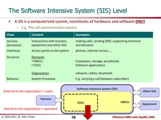
- 78. The Software Intensive System (SIS) Level • A SIS is a computerized system, constitutes of hardware and software ONLY – E.g. The cell communication system View Content Examples Services Interactions with humans, (purposes) equipment and other SISs making calls, sending SMS, supporting technical maintenance Interfaces Access points to the system phones, internet access, … Structure Elements • HWCIs • CSCIs Organization Computers, storage, peripherals Software applications network, cables, bluetooth Behavior System Processes E.g. carrying a call between subscribers Software Intensive System (SIS) External to the organization = users Other SISs CSCIs HWCIs Humans Equipment Internal to the organization = operators © 2010-2011, Dr. Amir Tomer 78 Effective MBD with SysML/UML
- 79. The CSCI Level • A CSCI is an aggregation of software that satisfies an end use function… [MIL-STD-498] – E.g. The cellphone’s phone-call software View Content Examples Services (purposes) End use functions placing calls, receiving calls, sending SMS Interfaces Commands, data and signals via hardware ports Receive/Transmit messages, touch screen Structure Elements Software Components (CSCs) Organization SW-SW communication Rx/Tx drivers, GUI, DLLs, … message passing, internal mailboxes Behavior Algorithms/Procedures Dial-send-connect-talk-hangup CSCI CSCs HW Devices Other CICs © 2010-2011, Dr. Amir Tomer 79 Effective MBD with SysML/UML
- 80. The CSC Level • A CSC is a (physical) piece of software that provides a set of defined functions – E.g. The cellphone GUI View Content Examples Services (purposes) Defined functions Edit a number, search a contact Interfaces Function calls, data messages send(“0598732567”), display(contact) Structure Elements Software units Organization Program structure, API Classes, blocks, procedures Behavior Execution threads CSC CSUs HW Devices Other CSCs © 2010-2011, Dr. Amir Tomer 80 Effective MBD with SysML/UML
- 81. The CSU Level • A CSU is a software unit, implementing certain function(s), usually constructed and tested by a single programmer – E.g. The dialing dialog box View Content Examples Services Defined functions (purposes) Interfaces function(X,Y,Z) Structure Code structure Behavior Code flow CSUs Other CSUs © 2010-2011, Dr. Amir Tomer 81 Effective MBD with SysML/UML
- 82. Recommended UML Models per Levels/Views View Level Services Interfaces Structure Behavior Business Use Case Diagram Composite Structure • Composite Structure • PDOM • Activity Diagram • State Machine SIS Use Case Diagram Composite Structure Deployment Diagram • Activity Diagram • State Machine CSCI Use Case Diagram Composite Structure with Port Delegation (CSCIs inside HWCIs) Component Diagram Sequence Diagram (CSCs) CSC CSC’s specific activity lines derived from CSCI’s Seq. Diag. Incoming/outgoing messages in CSCI’s Seq. Diag. Class Diagram Sequence Diagram (Objects) CSU Methods/Functions API (code.h) Class Specification • State Machine • Code © 2010-2011, Dr. Amir Tomer 82 Effective MBD with SysML/UML
- 83. Agenda • Modeling in Systems Engineering • Systems and Blocks • Modeling the Block’s Different Views • Modeling in the System Development Life Cycle • Modeling the Entire System’s Life Cycle • Modeling Computer Embedded Systems A Case-Study of System Modeling • Conclusions and Wrap-up © 2010-2011, Dr. Amir Tomer 83 Effective MBD with SysML/UML
- 84. UnderMiner – Brief Overview • Purpose – UnderMiner is a military system supporting a unit of the Engineering Corps in dealing with a set of suspected tunnels • Capabilities – Scanning: providing a 3D tunnel map + motion track – Trapping: Scattering mines inside a tunnel – Clearing: Shooting at objects within a tunnel • Structure – Mole: The end unit – a small robot with navigation, sensing, shooting, scattering mines and self-explosion capabilities • Each Mole is operated by a mole operator – C4I: The central command and control computer, controlling up to 8 moles • The C4I and the commander’s and operators’ workstations are located in a C4I wagon © 2010-2011, Dr. Amir Tomer 84 Effective MBD with SysML/UML
- 85. UnderMiner – Operational Highlights • An Operation – An operation command is received from Headquarters – The UM commander plans the operation and assign missions to moles – Each operator inserts its mole into a tunnel and controls its mission from his workstation in the C4I wagon – Upon mission completion each mole returns to tunnel entrance and collected by its operator – Moles can identify and report problematic situations; when necessary destruction may be directed by the commander – The operation status is reported continuously and on-demand to Headquarters All the rest, including details, should be obvious from the selected models in the following slides © 2010-2011, Dr. Amir Tomer 85 Effective MBD with SysML/UML
- 86. UnderMiner: Business Level - Services UnderMiner unit Headquarters Operation Initiation Operation Monitoring «include» Operation Execution UM commander Mole operator © 2010-2011, Dr. Amir Tomer 86 Effective MBD with SysML/UML
- 87. UnderMiner: Business Level – Interfaces + Structure This diagram captures both Business Level and System Level interfaces :Headquarters Tactical NW C4I unit 1..8 :Mole operator :UM commander Operator WS WiFi UnderMiner System (UMS) WiFi Commander WS NW Mole © 2010-2011, Dr. Amir Tomer 87 Effective MBD with SysML/UML
- 88. UnderMiner: Business Level – Conceptual Structure (PDOM) 1 1 allocate UMCommander «abstract» Mission 1 1..8 1..8 browse 1..8 Track operate 1 execute 1 MoleOperator Mole 1 OperationPlan 1 Operation ScanMission AssaultMission TrapMission 1 manage 1 UpperCommand Tunnel DestructionMech ShootingMech Mov ementMech MiningMech browse produced from 0..1 1 1 1 1 1 1 1 1 1 1 1 provide 0..1 1 1 1 plan approve 1..* 1 TunnelMap SnapShot SensorArray Sensor 1 1..* 1 0..* © 2010-2011, Dr. Amir Tomer 88 Effective MBD with SysML/UML
- 89. UnderMiner: Business Level – Behavior(1) • Modeling the Business Logic with Activity Diagram can provide clear and consistent transition from Business Level Use Cases to System Level Use Cases Business Behavior «structured» Operation Initiation Command Transfer Operation Planning [rejected] plan approval [approved] Mission Allocation «structured» Operation Execution Operation Plan «datastore» Mission Table Operation Command Mission Execution (scan/trap/clear) 1..8 Preparation for Mission Mission Terminated [change] [completion] [trouble] [no] [yes] Self Destruction? Mole Shutdown Mole Destruction [continue] Commander Decision Operation Termination Operation Initiation Status Demand «datastore» Collected Data «structured» [destroy] Operation Monitoring «loop» Periodic Report Status Report Report Type Operation Status 0..8 [periodic] [on demand] Business Services UnderMiner unit Headquarters Operation Initiation Operation Monitoring «include» Operation Execution UM commander Mole operator SIS Services (Ucs) © 2010-2011, Dr. Amir Tomer 89 Effective MBD with SysML/UML
- 90. UnderMiner: Business Level – Behavior(2) «structured» Operation Initiation Command Transfer Operation Planning Preparation for Mission [rejected] plan approval [approved] Mission Allocation Operation Plan «datastore» Mission Table Operation Initiation Operation Command © 2010-2011, Dr. Amir Tomer 90 Effective MBD with SysML/UML
- 91. UnderMiner: Business Level – Behavior(3) «structured» Operation Execution «datastore» Mission Table Mission Execution (scan/trap/clear) 1..8 Preparation for Mission Mission Terminated [change] [completion] [trouble] [no] [yes] Self Destruction? Mole Shutdown Mole Destruction [continue] Commander Decision Operation Termination Status Demand «datastore» Collected Data «structured» [destroy] Operation Monitoring «loop» Periodic Report Status Report Report Type Operation Status 0..8 [periodic] [on demand] © 2010-2011, Dr. Amir Tomer 91 Effective MBD with SysML/UML
- 92. UnderMiner: SIS Level – Services (1): UC Diagram UM commander UnderMiner System (UMS) Preparation for Mission Performing Scanning Command Allocation Transfer Operation Planning Performing Mole operator Trapping Ferforming Clearing Mole Mole Startup Mole Shutdown Destruction Headquarters (from Business Level UC) Operation Termination Monitoring and Report Status Report Mission Taking Over Operator © 2010-2011, Dr. Amir Tomer 92 Effective MBD with SysML/UML 1..8 «extend» «extend» «extend» «include» «include» «include»
- 93. UnderMiner: SIS Level – Services (2): UC Specification SUC-3 Mission Allocation Actors & Goals UM Commander: Allocate Missions to Mole Operators Mole Operators [1..8]: Supporting Actors Stakeholders & interests Headquarters: Mission is understood and executable pre-conditions Approved mission plan exists in the system [assured by SUC-2] post-conditions Mole mission table exists Each mole’s mission is approved by its operator trigger UM Commander operates “mission allocation” on his workstation MSS 1. UM Commander generates/updates the mole mission table 2. The System stores the mission table 3. The System notifies the operator about allocated/changed missions 4. Each Operator retrieves its mole’s mission from the mission table 5. Each Operator verifies that the mission is understood and approves it 6. The System records the approval at the mission table 7. UM Commander verifies that all operators approved their missions Branch A Alternative at step 5 of MSS: 5A1. The Operator applies to the UM Commander to check the mission together 5A2. The Operator updates the mission table as necessary 5A3. Back to step 2 © 2010-2011, Dr. Amir Tomer 93 Effective MBD with SysML/UML
- 94. UnderMiner: SIS Level – Accessibility Consistency UnderMiner System (UMS) Performing Scanning Operation Planning UM commander Preparation for Mission Performing Mole operator Trapping Ferforming Clearing Mole Destruction Headquarters 1..8 :Mole operator :UM commander (from Business Level UC) Operation Termination Status Report Mission Command Allocation Transfer Mole Shutdown Monitoring and Report Mole Startup Taking Over Operator 1..8 «extend» «extend» «extend» «include» «include» «include» :Headquarters Tactical NW C4I unit Operator WS WiFi UnderMiner System (UMS) WiFi Commander WS NW Mole © 2010-2011, Dr. Amir Tomer 94 Effective MBD with SysML/UML
- 95. UnderMiner: SIS Level – Structure (Operations Configuration) © 2010-2011, Dr. Amir Tomer 95 Effective MBD with SysML/UML
- 96. UnderMiner: SIS Level – Behavior (Realization of the “Perform Scanning” Use Case ) Mole C4I "GO" command transfer Mov ing in Tunnel Sensor sampling Image & track transmission Switch to manual Destruction Indication to commander and operator Tunnel map generarion Map display to operator Track display to commander stop? [yes] [no] Comm. resumed? [mole stuck] [end of route] Back to entrance success? «datastore» Images & Tracks Image Track [no] [yes] Stop & wait for comm. resume [yes] [no] [trouble] [mole clash] [stopped by operator] As the system is composed only of 2 elements (C4I, Mole) an Activity Diagram with swim-lanes was preferred here over Sequence Diagram © 2010-2011, Dr. Amir Tomer 96 Effective MBD with SysML/UML
- 97. UnderMiner: CSCI Level - Services • As the SIS Level UCD may simply partitioned into C4I UCs and Mole UCs, the same diagram may be used for the CSCI Level – The UC Specifications may be used as well, but if necessary the can be re-specified based on the swim-laned activity diagrams, as in the “scanning” example above UnderMiner System (UMS) C4I Mole Performing Scanning Operation Planning UM commander Preparation for Mission Performing Mole operator Trapping Ferforming Clearing Mole Destruction Headquarters (from Business Level UC) Operation Termination Status Report Mission Command Allocation Transfer Mole Shutdown Monitoring and Report Mole Startup Taking Over Operator 1..8 «extend» «extend» «extend» «include» «include» «include» © 2010-2011, Dr. Amir Tomer 97 Effective MBD with SysML/UML
- 98. UnderMiner/C4I SW: CSCI Level – Structure (SW Architecture) Upper Command Headquarters Interface «GUI» C&C Commander HMI Commanded C&C Data Services Data Services Data Services Command & Takeover Maps & Tunnel Mapping Manual Maneuvering Operator HMI Operator C&C Mole Operation «GUI» Data Management Tracks Processing Sensor Sampling Image © 2010-2011, Dr. Amir Tomer 98 Effective MBD with SysML/UML
- 99. UnderMiner/C4I SW: CSCI Level – Structure + Interfaces Tactic NW Commander WS Operator WS C4I SW Upper Command «delegate» Headquarters Interface C&C Commander HMI Data Services Data Services Data Services Command & Takeover Maps & Tunnel Mapping Manual Maneuvering Operator HMI «delegate» «delegate» Internal NW «GUI» Commanded C&C «delegate» Operator C&C Mole Operation «GUI» Data Management Tracks Processing Sensor Sampling Image «delegate» «delegate» The <<delegate>> relations provide the Surround Consistency © 2010-2011, Dr. Amir Tomer 99 Effective MBD with SysML/UML
- 100. UnderMiner/Mole SW: CSCI Level – Structure + Interfaces Sensor Array Motion Mechanism Shooting Mechanism Destruction Mechanism Mining Mechanism Internal NW Mole SW Sensor Command & Input «driver» Sense C&C Sensor Sampling «delegate» Motion Mech C&C «delegate» «driver» Motion C&C «delegate» Shooting Mech C&C «driver» Shooting C&C «delegate» Destruction Mech C&C «driver» Destruction C&C «delegate» Mining Mech C&C «driver» Mining C&C «delegate» Sensor Navigation & «delegate» Manual Maneuvering Maneuvering Mission Sensor C&C «delegate» Mole Management C&C Sampling Motion operation Shooting Operation Destruction Operation Navigation & Maneuvering Operation Mining Operation © 2010-2011, Dr. Amir Tomer 100 Effective MBD with SysML/UML
- 101. UnderMiner/C4I SW: CSCI Level – Behavior (Realization of the “Performing Clearing” Use Case) Mole operator «GUI» C4I SW::Operator HMI Mole SW::Mission Management «driver» Mole SW::Shooting C&C Shooting Mechanism Start Clearing Mission() alt Halt Reason [Trouble] [End of Tunnel] *[to end of tunnel]:Ongoing Shooting() ref Motion in Tunnel ref Mole Destruction Start_Clearing( ) Start Shooting() Start Motion() Trouble() Stop Shooting() Back to Entrance() Data Services Command & Takeover Maps & Sensor Command & Input Upper Command «driver» Sense C&C {1..8} Sensor Sampl ing Sensor C&C Motion operation Preparation for Mission Mole Startup Mole «include» Shutdown © 2010-2011, Dr. Amir Tomer 101 Effective MBD with SysML/UML Motion Mech C&C «driver» Motion C&C Shooting Mech C&C «driver» Shooting C&C Destruction Mech C&C «driver» Destruction C&C Mining Mech C&C «driver» Mining C&C Navigation & Manual Maneuvering Maneuvering Mission Mole Management C&C Sensor Sampl ing Destruction Operation Mining Operation Shooting Operation Navigation & Maneuvering Operation Mole Performing Scanning Performing Mole operator Trapping Ferforming Clearing Mole Destruction «extend» «extend» «extend» «GUI» Commander HMI Commanded C&C Manual Maneuvering Mole Operation «GUI» Operator HMI Operator C&C Headquarters Interface Data Management Sensor Sampling Image Processing C&C Data Services Tunnel Mapping Tracks Data Services
- 102. UnderMiner/Mole SW/Sense C&C: CSC Level – Services Sense C&C (CSC) Continuous Scanning Continuous Scanning Initiation Mission Sensor Array Continuous Scanning Termination Data Request Management (CSC) (Any Sample Consumer) C4I SW::Image Processing «driver» 1..8 Mole SW::Sense C&C «GUI» C4I SW::Operator HMI Start Continuous Display() loop [As long as the mole is active] Read Sensor Sample() :Sensor Sample Update Tunnel Map() Transmit Updated Map() Update Tunnel Display() © 2010-2011, Dr. Amir Tomer 102 Effective MBD with SysML/UML
- 103. UnderMiner/Mole SW/Sense C&C: CSC Level – Interfaces Sensor Command & Input «driver» Sense C&C Sensor Sampl ing Motion Mech C&C «driver» Motion C&C Shooting Mech C&C «driver» Shooting C&C Destruction Mech C&C «driver» Destruction C&C Mining Mech C&C «driver» Mining C&C Navigation & Manual Maneuvering Maneuvering Mission Sensor C&C Mole Management C&C Sensor Sampl ing Motion operation Shooting Operation Destruction Operation Navigation & Maneuvering Operation Mining Operation © 2010-2011, Dr. Amir Tomer 103 Effective MBD with SysML/UML
- 104. UnderMiner/Mole SW/Sense C&C: CSC Level – Structure SnapShot + timeTag: time - sampleVector: surfacePoint [1..*] + collectSampleData() : void provide 0..* 1 SensorArray - isActive: boolean + startScanning() : void + stopScanning() : void + storeSnapShot() : void + getLatestSample() : SnapShot + retrieveSnapShot() : SnapShot surfacePoint + Phi: float + Theta: float + Radius: float + Rigidity: float Sensor + sensorID: int + Phi: float + Theta: float - isActive: boolean + lastRadius: float + lastRigidity: float report + getLastSurfacePoint() : surfacePoint + getStatus() : byte sampleConsumerIF - dataMessage: bitstream 1 1..* + dataRequest(C :channel) : void - sendData(C :channel) : void + appendSnapShot(Msg :bitstream*, Snp :SnapShot) : void © 2010-2011, Dr. Amir Tomer 104 Effective MBD with SysML/UML
- 105. UnderMiner/Mole SW/Sense C&C: CSC Level – Behavior :sampleConsumerIF :SensorArray S :SnapShot dataRequest(myChannel) loop [while snapshots exist] dataMessage= EMPTY() S= getLatestSample() retrieveSnapShot() appendSnapShot(dataMessage,S) sendData(myChannel) SnapShot + timeTag: time - sampleVector: surfacePoint [1..*] + collectSampleData() : void provide 0..* 1 SensorArray - isActive: boolean + startScanning() : void + stopScanning() : void + storeSnapShot() : void + getLatestSample() : SnapShot + retrieveSnapShot() : SnapShot surfacePoint + Phi: float + Theta: float + Radius: float + Rigidity: float Sensor + sensorID: int + Phi: float + Theta: float - isActive: boolean + lastRadius: float + lastRigidity: float report + getLastSurfacePoint() : surfacePoint + getStatus() : byte sampleConsumerIF - dataMessage: bitstream 1 1..* + dataRequest(C :channel) : void - sendData(C :channel) : void + appendSnapShot(Msg :bitstream*, Snp :SnapShot) : void Sense C&C (CSC) Continuous Scanning Continuous Scanning Initiation Mission Sensor Array Continuous Scanning Termination Data Request Management (CSC) (Any Sample Consumer) © 2010-2011, Dr. Amir Tomer 105 Effective MBD with SysML/UML
- 106. UnderMiner/Mole SW/Sense C&C/sampleConsumerIF: CSU Level – Structure + Behavior (in code) sampleConsumerIF - dataMessage: bitstream + dataRequest(C :channel) : void - sendData(C :channel) : void + appendSnapShot(Msg :bitstream*, Snp :SnapShot) : void public class sampleConsumerIF { private bitstream dataMessage; public sampleConsumerIF(){ } public void dataRequest(channel C){ To be programmed … } private void sendData(channel C){ } public void appendSnapShot(bitstream Msg, SnapShot Snp){ } } :sampleConsumerIF :SensorArray S :SnapShot dataRequest(myChannel) loop [while snapshots exist] dataMessage= EMPTY() S= getLatestSample() retrieveSnapShot() appendSnapShot(dataMessage,S) sendData(myChannel) © 2010-2011, Dr. Amir Tomer 106 Effective MBD with SysML/UML
- 107. Agenda • Modeling in Systems Engineering • Systems and Blocks • Modeling the Block’s Different Views • Modeling in the System Development Life Cycle • Modeling the Entire System’s Life Cycle • Modeling Computer Embedded Systems • A Case-Study of System Modeling Conclusions and Wrap-up © 2010-2011, Dr. Amir Tomer 107 Effective MBD with SysML/UML
- 108. Summary of Important Concepts of the Introduced Methodology • The recursive-hierarchical nature of a system-of-interest – Both systems and elements, at all levels, fall into the unified concept of “block” • The 3-4 views of a block – Services, interfaces, (structure), behavior – Must be consistent with each other • Applying modeling iteratively throughout the SEP – Requirements = services + interfaces – Functional/Logical design = logical structure + logical behavior – Physical design = physical structure + physical behavior • Systematic breakdown modeling – The requirement models of a sub-blocks are directly derived from the design models of its parent block • Single architecture, multiple configurations – The architecture is an abstract configuration of the block – The architecture is the union of all its configurations • The 5 levels-of-interest of software Intensive Systems – Business, SIS, CSCI, CSC, CSU © 2010-2011, Dr. Amir Tomer 108 Effective MBD with SysML/UML
- 109. Jump-start System Modeling • If you have not done this before… 1. Be convinced about the importance of system modeling 2. Convince others to join your effort 3. Get a reliable tool (e.g. Enterprise Architect, Visual Paradigm, Rhapsody) 4. Start with modeling an existing system (e.g. one which is to be upgraded) 5. Start with simple atomic low-level elements and work bottom-up 6. Perform brainstorming and peer-reviews 7. Verify that this effort contributes real added value to your systems engineering activities • Have a good luck and enjoy! © 2010-2011, Dr. Amir Tomer 109 Effective MBD with SysML/UML
- 110. Any questions? [email protected] 052-8890202 © 2010-2011, Dr. Amir Tomer 110 Effective MBD with SysML/UML