SlideShare a Scribd company logo
CENTRE OF DIPLOMA STUDIES


COMPUTER ADDED DESIGN LABORATORY


   LABORATORY INSTRUCTION SHEET


                        DEK 3133
Subject Code and Name
                        MICROCONTROLLER

  Experiment Code       03

                        Introduction to functions, conditions and
   Experiment Title     Hardware Timer using TMR0

    Course Code         DET/DEE/DEX
Document Reference
                         No.                     RPP-05                 Page. Number            Page |1
                                                                        Edition                   1
                                                   LABORATORY           Revision No.               4
                            Document Title
                                                    PRACTICUM           Effective Date          27/7/2010
                                                                        Amendment Date          27/7/2010

                                        SUBJECT INFORMATION

SUBJECT         : DEK 3133 MICROCONTROLLER

TOPIC           : Lab 3 – Introduction to functions, conditions and Hardware Timer using TMR0

AIM             : Learn the further programming technique using C language


1       OBJECTIVES

         1.1   To understand the concept of programming in C using functions and conditions

         1.2   To learn how to use TMR0 as a hardware timer


2       EQUIPMENT


         2.1   PIC Development Board – PICDEV

         2.2   MPLAB IDE Program

         2.3   Mikro C

         2.4   Proteus

         2.5   The PIC Development Board User manual

         2.6   Power supply 9V
Document Reference
                         No.                        RPP-05                  Page. Number               Page |2
                                                                            Edition                      1
                                                      LABORATORY            Revision No.                      4
                              Document Title
                                                       PRACTICUM            Effective Date             27/7/2010
                                                                            Amendment Date             27/7/2010

3       THEORY

          3.1   Functions


          3.2   Conditions


          3.3 Using TMR0
         The special file register 01, Timer Zero (TMR0), which can be used as a counter or timer which, once
         started, run independently of the program execution. This mean it can count inputs or clock pulses
Document Reference
                          No.                       RPP-05                 Page. Number               Page |3
                                                                           Edition                      1
                                                      LABORATORY           Revision No.                     4
                              Document Title
                                                       PRACTICUM           Effective Date              27/7/2010
                                                                           Amendment Date              27/7/2010

        concurrently with the program. The counter/timer can also be set up to generate an interrupt when it has
        reached its maximum value, so that the main program does not have to keep checking it to see if a
        particular count has been reached.

         3.4       REGISTERS ASSOCIATED WITH TIMER0


    •    TMR0
           o 8 bit TMR0 Module Register
           o Count from 0 to 255 (00h to FFh)

    •    INTCON
               o GIE - Global Interrupt Enable bit - controls all possible interrupt sources
                 simultaneously.
                        1 - Enables all unmasked interrupts.
                        0 - Disables all interrupts.
               o    T0IE - TMR0 Overflow Interrupt Enable bit controls interrupt enabled by TMR0 overflow.
                            1 - Enables the TMR0 interrupt.
                            0 - Disables the TMR0 interrupt.
               o    T0IF - TMR0 Overflow Interrupt Flag bit registers the timer TMR0 register overflow, when
                    counting starts from zero.
                            1 - TMR0 register has overflowed (bit must be cleared in software).
                            0 - TMR0 register has not overflowed.
Document Reference
                      No.                         RPP-05                  Page. Number     Page |4
                                                                          Edition            1
                                                    LABORATORY            Revision No.        4
                           Document Title
                                                     PRACTICUM            Effective Date   27/7/2010
                                                                          Amendment Date   27/7/2010


    •   OPTION
          o TOCS – Clock Select bit (Bit 5)
                  1 – Pulses are brought to TMR0 timer/counter input through the RA4 pin
                  0 – Internal cycle clock (Fosc/4)

           o   TOSE – Source Edge Select bit (Bit 4)
                      1 – Increment on high to low transition on TMR0 pin
                      0 – increment on low to high transition on TMR0 pin
           o   PSA – Prescaler Assignment bit (Bit 3)
                      1 – Prescaler is assigned to the WDT
                      0 – Prescaler is assigned to the TMR0 timer/counter
           o   PS2 (Bit 2), PS1(Bit 1), PS0 (Bit 0) – Prescaler Rate Select bit

               PS2              PS1               PS0            TMR0             WDT
                0                 0                0                1:2             1:1
                0                 0                1                1:4             1:2
                0                 1                0                1:8             1:4
                0                 1                1               1:16             1:8
                1                 0                0               1:32            1:16
                1                 0                1               1:64            1:32
                1                 1                0              1:128            1:64
                1                 1                1              1:256           1:128


 Prepared By:                                               Approved by: 
                                                            
Signature :                                                Signature: 
Name: Mohamad Bin Md. Som                                  Name: Shamsul B. Mohamad 
Date: 27 July 2010                                         Date: 27 July 2010 
Document Reference
                         No.                       RPP-05                  Page. Number              Page |5
                                                                           Edition                     1
                                                      LABORATORY           Revision No.                   4
                             Document Title
                                                       PRACTICUM           Effective Date            27/7/2010
                                                                           Amendment Date            27/7/2010

4       ATTENTION

         4.1      Do not move any IC or device inside the board without any order from your instructor.


5       EXPERIMENT PROCEDURE

         5.1     Functions and Conditions

         5.1.1    Base on the circuit below (circuit 1), key in the given C code and simulate it using 
                  Proteus. Write your observations. 


                                                    Circuit 1
Document Reference
                        No.                       RPP-05                  Page. Number              Page |6
                                                                          Edition                     1
                                                    LABORATORY            Revision No.                   4
                           Document Title
                                                     PRACTICUM            Effective Date            27/7/2010
                                                                          Amendment Date            27/7/2010

#define       BUTTON1   PORTA.F0
#define       BUTTON2   PORTA.F1
#define       BUTTON3   PORTA.F2
#define       BUTTON4   PORTA.F3

void pattern1(void)             //function for pattern 1
{
  PORTB = 0b11111111;
}
void pattern2(void)             //function for pattern 2
{
  PORTB = 0b10101010;
}
void pattern3(void)             //function for pattern 3
{
  PORTB = 0b11110000;
}
void pattern4(void)             //function for pattern 4
{
  PORTB = 0b00001111;
}

void main(void)
{
     ADCON1 = 0b00000110; //Set ADCON1 for Port A as a digital input
     TRISA = 0b11111111; //Port A as input port
     TRISB = 0b00000000; //Port B as output port
     PORTB = 0b00000000; //Clear PORTB at start up

     while(1) //endless loop
     {
        if (BUTTON1 == 1) //Test button at PORTA bit 0 if pressed.
             pattern1();   //call function pattern1
        else if (BUTTON2 == 1)
             pattern2();   //call function pattern2
        else if (BUTTON3 == 1)
             pattern3();   //call function pattern3
        else if (BUTTON4 == 1)
             pattern4();   //call function pattern4
        else
             PORTB = 0b00000000; //All LED off if no button pressed
     } //end of while (endless loop)
}//end of main func

        5.2    Assignment 1.


Base on the Circuit 1, Modify the C code so that each button have a different pattern of animated LEDs. Use 1
second delay for each changing pattern. Test your result in Proteus and put your modifying code in the report.
Document Reference
                   No.                       RPP-05                Page. Number             Page |7
                                                                   Edition                    1
                                               LABORATORY          Revision No.                  4
                        Document Title
                                                PRACTICUM          Effective Date            27/7/2010
                                                                   Amendment Date            27/7/2010

    5.3     Using TMR0 as a Hardware Timer


                                             Circuit 2

    5.3.1    Base on the figure above (Circuit 2), the PIC use 4Mhz for its clock speed. Write the 
             program to blink the LED every one second by using TMR0. The code is shown below. 

    #define   LED1 PORTB.F0
    #define   TOCS OPTION_REG.F5
    #define   TOSE OPTION_REG.F4
    #define   PSA OPTION_REG.F3
    #define   PS2 OPTION_REG.F2
    #define   PS1 OPTION_REG.F1
    #define   PS0 OPTION_REG.F0

    #define GIE INTCON.F7
    #define TMR0IE INTCON.F5
    #define TMR0IF INTCON.F2

    //Public Variable
    unsigned int overflow;
    void interrupt(void)   //Interrupt subroutine
    {
      if (TMR0IE == 1 && TMR0IF == 1) //TMR0 made interrupt
Document Reference
                    No.                       RPP-05                Page. Number              Page |8
                                                                    Edition                     1
                                                LABORATORY          Revision No.                   4
                          Document Title
                                                 PRACTICUM          Effective Date            27/7/2010
                                                                    Amendment Date            27/7/2010

        {
            overflow++;
            TMR0IF = 0;       //clear interrupt flag
            TMR0IE = 0;       //Disable TMR0 interrupt

            if (overflow == 15) //TMR0 is overflow about 15 times ~~ 1 second.
            {
               LED1 = ~LED1;
               overflow = 0;   //reset overflow to 0
            }
            TMR0IE = 1;    //enable TMR0 interrupt
            TMR0 = 0;      //restart TMR0 value to 0
        }

    }

    void main(void)
    {
      overflow = 0;
      //port setup
      TRISB = 0; //port B is output
      PORTB = 0; //initial value for PORTB is 0

        //TMR0 setup
        TOCS = 0; //Internal cycle clock (Fosc/4)
        PSA = 0;   //Prescaler is assinged to the TMR0 timer
        PS2 = 1;
        PS1 = 1;
        PS0 = 1;   //Prescaler rate is selected to 1:256
        TMR0 = 0; //Initial value for TMR0 is 0

        //Interrupt Setup
        GIE = 1;    //Enable all interrupt
        TMR0IE = 1; //Enable the TMR0 interrupt

        while(1);    //infinite loop

    }

    5.3.2    Burn the *.hex file into PIC and test the PIC at the development board. Write your 
             observation in the report. 

    5.4     Assignment 2

    5.4.1    Write a C program so that the LED is blinking using hardware delay which is blinking 
             every 1 second. Assume PIC clock speed is 1MHz and prescaler used is 1:256. Simulate 
             your result using Proteus. 
Document Reference
                             No.                       RPP-05             Page. Number               Page |9
                                                                          Edition                      1
                                                         LABORATORY       Revision No.                  4
                                Document Title
                                                          PRACTICUM       Effective Date             27/7/2010
                                                                          Amendment Date             27/7/2010


6       REPORT PREPARATION AND SCHEMA.


(1)       2 persons for 1 report.

(2)       Due date to send report is 1 weeks after lab date.

(3)       Report schema following below requirements:

        • Lab report cover sheet for 1st page.
        • Objective, theory, equipments for the 2nd page. (5)                              (5M)
        • Observations. (20)
           1. Observations from 5.1.1 (Proteus Simulation)                                 (10 M)
           2. Observations from 5.3.2 (TMR0 run on development board)                      (10 M )
        • Result. (35)
                 1. Assignment 1 source code & Flow Chart                ( 15 M )
                 2. Assignment 2 source code & Proteus Simulation        ( 20 M )
        • Discussion. (25)
            1. List the Registers related to TMR0 and describes the procedure to setup the TMR0 (15M)
            2. If the PIC is supplied with 1 MHz clock speed, calculate time taken for TMR0 to
               overflow. Assume that a prescaler 1:256 is used. Show the calculation in your report
                                                                                           (10 M)


        • Conclusions. (15)

More Related Content

Viewers also liked (18)

DOC
Performance of dc motors experiment 2
Karimi LordRamza
 
PPS
Projek rekabentuk
mkazree
 
PDF
Projek rekabentuk1
mkazree
 
DOC
rekabentruk berbantu komputer Lab 4
mkazree
 
PDF
Mp lab
PRADEEP
 
DOCX
Introduction to pic
PRADEEP
 
PDF
19199406 embedded-c-tutorial-8051
PRADEEP
 
PDF
16f877
PRADEEP
 
DOC
Chapter 4 synchronous machine
mkazree
 
DOC
Tutorial 2 amplitude modulation
mkazree
 
DOC
120102011
mkazree
 
DOC
Tutorial chapter 3 robotic
mkazree
 
PDF
ADC Interfacing with pic Microcontrollert
leapshare007
 
PDF
Tutorial chapter 2 robotic
mkazree
 
PPT
8-bit PIC Microcontrollers
Premier Farnell
 
PPT
Unit 3 tables and data structures
PRADEEP
 
PDF
The Electronic Hobby Kit
mkazree
 
DOC
Foster-seely and Ratio Detector (Discriminator )
mkazree
 
Performance of dc motors experiment 2
Karimi LordRamza
 
Projek rekabentuk
mkazree
 
Projek rekabentuk1
mkazree
 
rekabentruk berbantu komputer Lab 4
mkazree
 
Mp lab
PRADEEP
 
Introduction to pic
PRADEEP
 
19199406 embedded-c-tutorial-8051
PRADEEP
 
16f877
PRADEEP
 
Chapter 4 synchronous machine
mkazree
 
Tutorial 2 amplitude modulation
mkazree
 
120102011
mkazree
 
Tutorial chapter 3 robotic
mkazree
 
ADC Interfacing with pic Microcontrollert
leapshare007
 
Tutorial chapter 2 robotic
mkazree
 
8-bit PIC Microcontrollers
Premier Farnell
 
Unit 3 tables and data structures
PRADEEP
 
The Electronic Hobby Kit
mkazree
 
Foster-seely and Ratio Detector (Discriminator )
mkazree
 

Similar to Lab 3 microcontroller (20)

PDF
Free SPICE Model of MA2YF80 in SPICE PARK
Tsuyoshi Horigome
 
PDF
Free SPICE Model of MA2YF80
Tsuyoshi Horigome
 
PDF
フォトインタラプタのスパイスモデル
spicepark
 
PDF
SPICE MODEL of S30SC4MT (Professional Model) in SPICE PARK
Tsuyoshi Horigome
 
PDF
SPICE MODEL of S30SC4MT (Professional Model) in SPICE PARK
Tsuyoshi Horigome
 
PDF
SPICE MODEL of CMH04 (Standard Model) in SPICE PARK
Tsuyoshi Horigome
 
PDF
SPICE MODEL of SG30SC6M (Professional Model) in SPICE PARK
Tsuyoshi Horigome
 
PDF
SPICE MODEL of SG30SC6M (Professional Model) in SPICE PARK
Tsuyoshi Horigome
 
PDF
SPICE MODEL of RN1965FS in SPICE PARK
Tsuyoshi Horigome
 
PDF
SPICE MODEL of TLWH1100 , White ,TA=40degree (Standard Model) in SPICE PARK
Tsuyoshi Horigome
 
PDF
SPICE MODEL of TLWH1100 , White ,TA=-20degree (Standard Model) in SPICE PARK
Tsuyoshi Horigome
 
PDF
SPICE MODEL of CMH04 (Professional Model) in SPICE PARK
Tsuyoshi Horigome
 
PDF
SPICE MODEL of RN1961FS in SPICE PARK
Tsuyoshi Horigome
 
PDF
Free SPICE Model of CMH07 in SPICE PARK
Tsuyoshi Horigome
 
PDF
SPICE MODEL of TLWH1100 , White ,TA=60degree (Standard Model) in SPICE PARK
Tsuyoshi Horigome
 
PDF
8051 Timers / Counters
Patricio Lima
 
PDF
SPICE MODEL of S60SC4MT (Professional Model) in SPICE PARK
Tsuyoshi Horigome
 
PDF
SPICE MODEL of SG30JC6M (Professional Model) in SPICE PARK
Tsuyoshi Horigome
 
PDF
SPICE MODEL of SG30JC6M (Professional Model) in SPICE PARK
Tsuyoshi Horigome
 
PDF
SPICE MODEL of SF10LC40 (Professional Model) in SPICE PARK
Tsuyoshi Horigome
 
Free SPICE Model of MA2YF80 in SPICE PARK
Tsuyoshi Horigome
 
Free SPICE Model of MA2YF80
Tsuyoshi Horigome
 
フォトインタラプタのスパイスモデル
spicepark
 
SPICE MODEL of S30SC4MT (Professional Model) in SPICE PARK
Tsuyoshi Horigome
 
SPICE MODEL of S30SC4MT (Professional Model) in SPICE PARK
Tsuyoshi Horigome
 
SPICE MODEL of CMH04 (Standard Model) in SPICE PARK
Tsuyoshi Horigome
 
SPICE MODEL of SG30SC6M (Professional Model) in SPICE PARK
Tsuyoshi Horigome
 
SPICE MODEL of SG30SC6M (Professional Model) in SPICE PARK
Tsuyoshi Horigome
 
SPICE MODEL of RN1965FS in SPICE PARK
Tsuyoshi Horigome
 
SPICE MODEL of TLWH1100 , White ,TA=40degree (Standard Model) in SPICE PARK
Tsuyoshi Horigome
 
SPICE MODEL of TLWH1100 , White ,TA=-20degree (Standard Model) in SPICE PARK
Tsuyoshi Horigome
 
SPICE MODEL of CMH04 (Professional Model) in SPICE PARK
Tsuyoshi Horigome
 
SPICE MODEL of RN1961FS in SPICE PARK
Tsuyoshi Horigome
 
Free SPICE Model of CMH07 in SPICE PARK
Tsuyoshi Horigome
 
SPICE MODEL of TLWH1100 , White ,TA=60degree (Standard Model) in SPICE PARK
Tsuyoshi Horigome
 
8051 Timers / Counters
Patricio Lima
 
SPICE MODEL of S60SC4MT (Professional Model) in SPICE PARK
Tsuyoshi Horigome
 
SPICE MODEL of SG30JC6M (Professional Model) in SPICE PARK
Tsuyoshi Horigome
 
SPICE MODEL of SG30JC6M (Professional Model) in SPICE PARK
Tsuyoshi Horigome
 
SPICE MODEL of SF10LC40 (Professional Model) in SPICE PARK
Tsuyoshi Horigome
 
Ad

More from mkazree (20)

PDF
Coal Fired Power Plant
mkazree
 
DOC
Contoh kertas kerja program
mkazree
 
PPT
Communication Engineering - Chapter 6 - Noise
mkazree
 
PPT
Chapter 5 fm receivers
mkazree
 
PPT
Dek3223 chapter 2 robotic
mkazree
 
PPT
Chapter 3 am receivers
mkazree
 
PPT
Dek3223 chapter 3 industrial robotic
mkazree
 
PPT
Chapter 3 am receivers
mkazree
 
PPT
Comm introduction
mkazree
 
PPT
Chapter2 cont
mkazree
 
PPT
Chapter 2 amplitude_modulation
mkazree
 
DOC
Chapter5 dek 3143 dae 32303 9 (nota tambahan)
mkazree
 
DOC
Ii20102011
mkazree
 
DOC
Chapter 3 induction machine
mkazree
 
DOC
Chapter 2 transformer new
mkazree
 
DOC
Chapter 1 dc machines new
mkazree
 
PPT
Chp7 pic 16 f84 interfacing - copy
mkazree
 
PPT
Chp1 68000 microprocessor copy
mkazree
 
PPT
Chp6 assembly language programming for pic copy
mkazree
 
PPT
Chp5 pic microcontroller instruction set copy
mkazree
 
Coal Fired Power Plant
mkazree
 
Contoh kertas kerja program
mkazree
 
Communication Engineering - Chapter 6 - Noise
mkazree
 
Chapter 5 fm receivers
mkazree
 
Dek3223 chapter 2 robotic
mkazree
 
Chapter 3 am receivers
mkazree
 
Dek3223 chapter 3 industrial robotic
mkazree
 
Chapter 3 am receivers
mkazree
 
Comm introduction
mkazree
 
Chapter2 cont
mkazree
 
Chapter 2 amplitude_modulation
mkazree
 
Chapter5 dek 3143 dae 32303 9 (nota tambahan)
mkazree
 
Ii20102011
mkazree
 
Chapter 3 induction machine
mkazree
 
Chapter 2 transformer new
mkazree
 
Chapter 1 dc machines new
mkazree
 
Chp7 pic 16 f84 interfacing - copy
mkazree
 
Chp1 68000 microprocessor copy
mkazree
 
Chp6 assembly language programming for pic copy
mkazree
 
Chp5 pic microcontroller instruction set copy
mkazree
 
Ad

Recently uploaded (20)

PPTX
How to Convert an Opportunity into a Quotation in Odoo 18 CRM
Celine George
 
PDF
Stokey: A Jewish Village by Rachel Kolsky
History of Stoke Newington
 
PPTX
care of patient with elimination needs.pptx
Rekhanjali Gupta
 
PDF
QNL June Edition hosted by Pragya the official Quiz Club of the University of...
Pragya - UEM Kolkata Quiz Club
 
PDF
Biological Bilingual Glossary Hindi and English Medium
World of Wisdom
 
PDF
Knee Extensor Mechanism Injuries - Orthopedic Radiologic Imaging
Sean M. Fox
 
PPT
Talk on Critical Theory, Part One, Philosophy of Social Sciences
Soraj Hongladarom
 
PPTX
I AM MALALA The Girl Who Stood Up for Education and was Shot by the Taliban...
Beena E S
 
PPTX
Post Dated Cheque(PDC) Management in Odoo 18
Celine George
 
PDF
The Constitution Review Committee (CRC) has released an updated schedule for ...
nservice241
 
PPTX
HUMAN RESOURCE MANAGEMENT: RECRUITMENT, SELECTION, PLACEMENT, DEPLOYMENT, TRA...
PRADEEP ABOTHU
 
PDF
Exploring the Different Types of Experimental Research
Thelma Villaflores
 
PDF
0725.WHITEPAPER-UNIQUEWAYSOFPROTOTYPINGANDUXNOW.pdf
Thomas GIRARD, MA, CDP
 
PDF
Geographical Diversity of India 100 Mcq.pdf/ 7th class new ncert /Social/Samy...
Sandeep Swamy
 
PPTX
QUARTER 1 WEEK 2 PLOT, POV AND CONFLICTS
KynaParas
 
PPTX
grade 5 lesson matatag ENGLISH 5_Q1_PPT_WEEK4.pptx
SireQuinn
 
PDF
ARAL_Orientation_Day-2-Sessions_ARAL-Readung ARAL-Mathematics ARAL-Sciencev2.pdf
JoelVilloso1
 
PDF
CONCURSO DE POESIA “POETUFAS – PASSOS SUAVES PELO VERSO.pdf
Colégio Santa Teresinha
 
PDF
DIGESTION OF CARBOHYDRATES,PROTEINS,LIPIDS
raviralanaresh2
 
PDF
Horarios de distribución de agua en julio
pegazohn1978
 
How to Convert an Opportunity into a Quotation in Odoo 18 CRM
Celine George
 
Stokey: A Jewish Village by Rachel Kolsky
History of Stoke Newington
 
care of patient with elimination needs.pptx
Rekhanjali Gupta
 
QNL June Edition hosted by Pragya the official Quiz Club of the University of...
Pragya - UEM Kolkata Quiz Club
 
Biological Bilingual Glossary Hindi and English Medium
World of Wisdom
 
Knee Extensor Mechanism Injuries - Orthopedic Radiologic Imaging
Sean M. Fox
 
Talk on Critical Theory, Part One, Philosophy of Social Sciences
Soraj Hongladarom
 
I AM MALALA The Girl Who Stood Up for Education and was Shot by the Taliban...
Beena E S
 
Post Dated Cheque(PDC) Management in Odoo 18
Celine George
 
The Constitution Review Committee (CRC) has released an updated schedule for ...
nservice241
 
HUMAN RESOURCE MANAGEMENT: RECRUITMENT, SELECTION, PLACEMENT, DEPLOYMENT, TRA...
PRADEEP ABOTHU
 
Exploring the Different Types of Experimental Research
Thelma Villaflores
 
0725.WHITEPAPER-UNIQUEWAYSOFPROTOTYPINGANDUXNOW.pdf
Thomas GIRARD, MA, CDP
 
Geographical Diversity of India 100 Mcq.pdf/ 7th class new ncert /Social/Samy...
Sandeep Swamy
 
QUARTER 1 WEEK 2 PLOT, POV AND CONFLICTS
KynaParas
 
grade 5 lesson matatag ENGLISH 5_Q1_PPT_WEEK4.pptx
SireQuinn
 
ARAL_Orientation_Day-2-Sessions_ARAL-Readung ARAL-Mathematics ARAL-Sciencev2.pdf
JoelVilloso1
 
CONCURSO DE POESIA “POETUFAS – PASSOS SUAVES PELO VERSO.pdf
Colégio Santa Teresinha
 
DIGESTION OF CARBOHYDRATES,PROTEINS,LIPIDS
raviralanaresh2
 
Horarios de distribución de agua en julio
pegazohn1978
 

Lab 3 microcontroller

  • 1. CENTRE OF DIPLOMA STUDIES COMPUTER ADDED DESIGN LABORATORY LABORATORY INSTRUCTION SHEET DEK 3133 Subject Code and Name MICROCONTROLLER Experiment Code 03 Introduction to functions, conditions and Experiment Title Hardware Timer using TMR0 Course Code DET/DEE/DEX
  • 2. Document Reference   No. RPP-05 Page. Number Page |1 Edition 1 LABORATORY Revision No. 4 Document Title PRACTICUM Effective Date 27/7/2010 Amendment Date 27/7/2010 SUBJECT INFORMATION SUBJECT : DEK 3133 MICROCONTROLLER TOPIC : Lab 3 – Introduction to functions, conditions and Hardware Timer using TMR0 AIM : Learn the further programming technique using C language 1 OBJECTIVES 1.1 To understand the concept of programming in C using functions and conditions 1.2 To learn how to use TMR0 as a hardware timer 2 EQUIPMENT 2.1 PIC Development Board – PICDEV 2.2 MPLAB IDE Program 2.3 Mikro C 2.4 Proteus 2.5 The PIC Development Board User manual 2.6 Power supply 9V
  • 3. Document Reference   No. RPP-05 Page. Number Page |2 Edition 1 LABORATORY Revision No. 4 Document Title PRACTICUM Effective Date 27/7/2010 Amendment Date 27/7/2010 3 THEORY 3.1 Functions 3.2 Conditions 3.3 Using TMR0 The special file register 01, Timer Zero (TMR0), which can be used as a counter or timer which, once started, run independently of the program execution. This mean it can count inputs or clock pulses
  • 4. Document Reference   No. RPP-05 Page. Number Page |3 Edition 1 LABORATORY Revision No. 4 Document Title PRACTICUM Effective Date 27/7/2010 Amendment Date 27/7/2010 concurrently with the program. The counter/timer can also be set up to generate an interrupt when it has reached its maximum value, so that the main program does not have to keep checking it to see if a particular count has been reached. 3.4 REGISTERS ASSOCIATED WITH TIMER0 • TMR0 o 8 bit TMR0 Module Register o Count from 0 to 255 (00h to FFh) • INTCON o GIE - Global Interrupt Enable bit - controls all possible interrupt sources simultaneously. 1 - Enables all unmasked interrupts. 0 - Disables all interrupts. o T0IE - TMR0 Overflow Interrupt Enable bit controls interrupt enabled by TMR0 overflow. 1 - Enables the TMR0 interrupt. 0 - Disables the TMR0 interrupt. o T0IF - TMR0 Overflow Interrupt Flag bit registers the timer TMR0 register overflow, when counting starts from zero. 1 - TMR0 register has overflowed (bit must be cleared in software). 0 - TMR0 register has not overflowed.
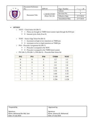
  • 5. Document Reference   No. RPP-05 Page. Number Page |4 Edition 1 LABORATORY Revision No. 4 Document Title PRACTICUM Effective Date 27/7/2010 Amendment Date 27/7/2010 • OPTION o TOCS – Clock Select bit (Bit 5) 1 – Pulses are brought to TMR0 timer/counter input through the RA4 pin 0 – Internal cycle clock (Fosc/4) o TOSE – Source Edge Select bit (Bit 4) 1 – Increment on high to low transition on TMR0 pin 0 – increment on low to high transition on TMR0 pin o PSA – Prescaler Assignment bit (Bit 3) 1 – Prescaler is assigned to the WDT 0 – Prescaler is assigned to the TMR0 timer/counter o PS2 (Bit 2), PS1(Bit 1), PS0 (Bit 0) – Prescaler Rate Select bit PS2 PS1 PS0 TMR0 WDT 0 0 0 1:2 1:1 0 0 1 1:4 1:2 0 1 0 1:8 1:4 0 1 1 1:16 1:8 1 0 0 1:32 1:16 1 0 1 1:64 1:32 1 1 0 1:128 1:64 1 1 1 1:256 1:128  Prepared By:   Approved by:      Signature :  Signature:  Name: Mohamad Bin Md. Som  Name: Shamsul B. Mohamad  Date: 27 July 2010  Date: 27 July 2010 
  • 6. Document Reference   No. RPP-05 Page. Number Page |5 Edition 1 LABORATORY Revision No. 4 Document Title PRACTICUM Effective Date 27/7/2010 Amendment Date 27/7/2010 4 ATTENTION 4.1 Do not move any IC or device inside the board without any order from your instructor. 5 EXPERIMENT PROCEDURE 5.1 Functions and Conditions 5.1.1 Base on the circuit below (circuit 1), key in the given C code and simulate it using  Proteus. Write your observations.  Circuit 1
  • 7. Document Reference   No. RPP-05 Page. Number Page |6 Edition 1 LABORATORY Revision No. 4 Document Title PRACTICUM Effective Date 27/7/2010 Amendment Date 27/7/2010 #define BUTTON1 PORTA.F0 #define BUTTON2 PORTA.F1 #define BUTTON3 PORTA.F2 #define BUTTON4 PORTA.F3 void pattern1(void) //function for pattern 1 { PORTB = 0b11111111; } void pattern2(void) //function for pattern 2 { PORTB = 0b10101010; } void pattern3(void) //function for pattern 3 { PORTB = 0b11110000; } void pattern4(void) //function for pattern 4 { PORTB = 0b00001111; } void main(void) { ADCON1 = 0b00000110; //Set ADCON1 for Port A as a digital input TRISA = 0b11111111; //Port A as input port TRISB = 0b00000000; //Port B as output port PORTB = 0b00000000; //Clear PORTB at start up while(1) //endless loop { if (BUTTON1 == 1) //Test button at PORTA bit 0 if pressed. pattern1(); //call function pattern1 else if (BUTTON2 == 1) pattern2(); //call function pattern2 else if (BUTTON3 == 1) pattern3(); //call function pattern3 else if (BUTTON4 == 1) pattern4(); //call function pattern4 else PORTB = 0b00000000; //All LED off if no button pressed } //end of while (endless loop) }//end of main func 5.2 Assignment 1. Base on the Circuit 1, Modify the C code so that each button have a different pattern of animated LEDs. Use 1 second delay for each changing pattern. Test your result in Proteus and put your modifying code in the report.
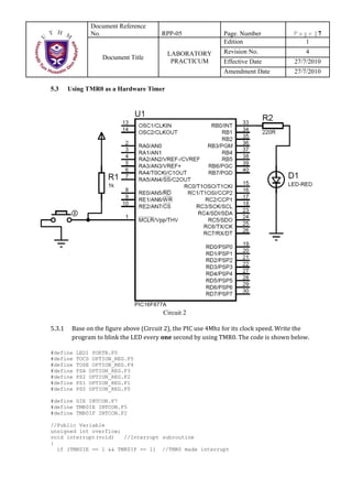
  • 8. Document Reference   No. RPP-05 Page. Number Page |7 Edition 1 LABORATORY Revision No. 4 Document Title PRACTICUM Effective Date 27/7/2010 Amendment Date 27/7/2010 5.3 Using TMR0 as a Hardware Timer Circuit 2 5.3.1 Base on the figure above (Circuit 2), the PIC use 4Mhz for its clock speed. Write the  program to blink the LED every one second by using TMR0. The code is shown below.  #define LED1 PORTB.F0 #define TOCS OPTION_REG.F5 #define TOSE OPTION_REG.F4 #define PSA OPTION_REG.F3 #define PS2 OPTION_REG.F2 #define PS1 OPTION_REG.F1 #define PS0 OPTION_REG.F0 #define GIE INTCON.F7 #define TMR0IE INTCON.F5 #define TMR0IF INTCON.F2 //Public Variable unsigned int overflow; void interrupt(void) //Interrupt subroutine { if (TMR0IE == 1 && TMR0IF == 1) //TMR0 made interrupt
  • 9. Document Reference   No. RPP-05 Page. Number Page |8 Edition 1 LABORATORY Revision No. 4 Document Title PRACTICUM Effective Date 27/7/2010 Amendment Date 27/7/2010 { overflow++; TMR0IF = 0; //clear interrupt flag TMR0IE = 0; //Disable TMR0 interrupt if (overflow == 15) //TMR0 is overflow about 15 times ~~ 1 second. { LED1 = ~LED1; overflow = 0; //reset overflow to 0 } TMR0IE = 1; //enable TMR0 interrupt TMR0 = 0; //restart TMR0 value to 0 } } void main(void) { overflow = 0; //port setup TRISB = 0; //port B is output PORTB = 0; //initial value for PORTB is 0 //TMR0 setup TOCS = 0; //Internal cycle clock (Fosc/4) PSA = 0; //Prescaler is assinged to the TMR0 timer PS2 = 1; PS1 = 1; PS0 = 1; //Prescaler rate is selected to 1:256 TMR0 = 0; //Initial value for TMR0 is 0 //Interrupt Setup GIE = 1; //Enable all interrupt TMR0IE = 1; //Enable the TMR0 interrupt while(1); //infinite loop } 5.3.2 Burn the *.hex file into PIC and test the PIC at the development board. Write your  observation in the report.  5.4 Assignment 2 5.4.1 Write a C program so that the LED is blinking using hardware delay which is blinking  every 1 second. Assume PIC clock speed is 1MHz and prescaler used is 1:256. Simulate  your result using Proteus. 
  • 10. Document Reference   No. RPP-05 Page. Number Page |9 Edition 1 LABORATORY Revision No. 4 Document Title PRACTICUM Effective Date 27/7/2010 Amendment Date 27/7/2010 6 REPORT PREPARATION AND SCHEMA. (1) 2 persons for 1 report. (2) Due date to send report is 1 weeks after lab date. (3) Report schema following below requirements: • Lab report cover sheet for 1st page. • Objective, theory, equipments for the 2nd page. (5) (5M) • Observations. (20) 1. Observations from 5.1.1 (Proteus Simulation) (10 M) 2. Observations from 5.3.2 (TMR0 run on development board) (10 M ) • Result. (35) 1. Assignment 1 source code & Flow Chart ( 15 M ) 2. Assignment 2 source code & Proteus Simulation ( 20 M ) • Discussion. (25) 1. List the Registers related to TMR0 and describes the procedure to setup the TMR0 (15M) 2. If the PIC is supplied with 1 MHz clock speed, calculate time taken for TMR0 to overflow. Assume that a prescaler 1:256 is used. Show the calculation in your report (10 M) • Conclusions. (15)