Advanced Frequency Shift Keying bandwidth needed for FSK depends on the distance between the carrier frequencies special pre-computation avoids sudden phase shifts    MSK (Minimum Shift Keying) bit separated into even and odd bits, the duration of each bit is doubled  depending on the bit values (even, odd) the higher or lower frequency, original or inverted is chosen the frequency of one carrier is twice the frequency of the other Equivalent to offset QPSK even higher bandwidth efficiency using a Gaussian low-pass filter    GMSK (Gaussian MSK), used in GSM
Advanced Frequency Shift Keying If Even and Odd bits are both zero : - f2 is inverted. If Even bit is 1 and odd bit is zero: -  Lower frequency f1 is inverted. If Even bit is zero and the odd bit is 1: -  f1 is taken without phase change, as is. If Both even and odd bits are 1 : -  frequency f2 is taken as is.
Example of MSK data even bits odd bits 1 1 1 1 0 0 0 t low  frequency high frequency MSK signal bit even 0 1 0 1 odd 0 0 1 1 signal h n n h value -  -  + + h: high frequency n: low frequency +: original signal -:  inverted signal No phase shifts!
Advanced Phase Shift Keying BPSK (Binary Phase Shift Keying): bit value 0: sine wave bit value 1: inverted sine wave very simple PSK low spectral efficiency robust, used e.g. in satellite systems QPSK (Quadrature Phase Shift Keying): 2 bits coded as one symbol symbol determines shift of sine wave needs less bandwidth compared to BPSK more complex Often also transmission of relative,  not absolute phase shift: DQPSK – - Differential QPSK (IS-136, PHS) 11 10 00 01 A t Q I 11 01 10 00
Quadrature Amplitude Modulation Quadrature Amplitude Modulation (QAM): combines amplitude and phase modulation it is possible to code n bits using one symbol 2 n  discrete levels, n=2 identical to QPSK bit error rate increases with n, but less errors compared to comparable PSK schemes Example: 16-QAM (4 bits = 1 symbol) Symbols 0011 and 0001 have the  same phase  φ , but  different  amplitudes.  0000 & 1000 have different phases but the same amplitude. 0000 0001 0011 1000 I 0010 φ a
Hierarchical Modulation DVB-T modulates two separate data streams onto a single DVB-T stream High Priority (HP) embedded within a Low Priority (LP) stream Multi carrier system, about 2000 or 8000 carriers QPSK, 16 QAM, 64QAM Example: 64QAM good reception: resolve the entire  64QAM constellation poor reception, mobile reception:  resolve only QPSK portion 6 bit per QAM symbol, 2 most  significant determine QPSK HP service coded in QPSK (2 bit),  LP uses remaining 4 bit I Q 10 00 00 0010 01 0101
Spread spectrum technology Problem of radio transmission: frequency dependent fading can wipe out narrow band signals for duration of the interference Solution: spread the narrow band signal into a broad band signal using a special code protection against narrow band interference  protection against narrowband interference Side effects: coexistence of several signals without dynamic coordination tap-proof Alternatives: Direct Sequence, Frequency Hopping detection at receiver interference spread signal signal f f power power
Spread spectrum technology MERITS OF SPREAD SPECTRUM Because Spread Spectrum signals are noise-like, they are hard to detect.  Spread Spectrum signals are harder to jam (interfere with) than narrowband signals   Spread Spectrum transmitters use similar transmit power levels to narrow band transmitters.  Because Spread Spectrum signals are so wide, they transmit at a much lower spectral power density, measured in Watts per Hertz, than narrowband transmitters.  power
Spread spectrum technology MERITS OF SPREAD SPECTRUM spread spectrum signals are hard to exploit or spoof.  Signal exploitation is the ability of an enemy (or a non-network member) to listen in to a network and use information from the network without being a valid network member or participant.  Spoofing is the act of falsely or maliciously introducing misleading or false traffic or messages to a network.  power
Spreading and Despreading – Resistance to narrow band interference dP/df f i) dP/df f ii) sender dP/df f iii) dP/df f iv) receiver f v) user signal broadband interference narrowband interference dP/df
Spreading and Despreading – Resistance to narrow band interference Original signal to be transmitted. The sender spreads the signal and converts the narrow-band signal to broadband (Power level can be much lower without losing data) During transmission, narrow and broadband noise gets added. The receiver despreads the given signal, narrow band interference is spread, leaving the broadband as it is. Receiver applies a band pass filter cutting off left & right of narrow band signal.
Spreading and frequency selective fading frequency channel quality 1 2 3 4 5 6 narrow band signal guard space narrowband channels spread spectrum channels
Problem with narrow band transmission (FDM) In the figure above, Frequencies 1,2 and 5 have reasonably good quality of service.  Frequencies 3 & 4 are of very narrow band and they can get corrupted. Spread Spectrum can help in such a situation.
How to fix the narrow band interference problem? 2 2 2 2 2 frequency channel quality 1 spread spectrum
Solution…. All narrow band signals are spread into broadband signals using the same frequency range To separate the Channels, CDM is used. Each channel is allocated its own code which the receivers know. Because of secret code, spread spectrum acts as a security protection.
DSSS (Direct Sequence Spread Spectrum) I XOR of the signal with pseudo-random number (chipping sequence) many chips per bit (e.g., 128) result in higher bandwidth of the signal Advantages reduces frequency selective  fading in cellular networks  base stations can use the  same frequency range several base stations can  detect and recover the signal soft handover Disadvantages precise power control necessary user data chipping  sequence resulting signal 0 1 0 1 1 0 1 0 1 0 1 0 0 1 1 1 XOR 0 1 1 0 0 1 0 1 1 0 1 0 0 1 = t b t c t b : bit period t c : chip period
Bandwidth of the resulting signal tc = Chip Period tb = Bit Period Spreading factor s -= tb/tc s*original bandwidth is the new bandwidth. It determines the BW of the resulting signal
Spreading Factor Most civil applications need a spreading factor of 10 to 100. Military applications use a speeding factor of around 10,000.
Barker Codes 10110111000 (802.11 wireless LANS) 11 110 1110 11101 1110010 1111100110101
Barker Codes Let the code to be transmitted be 110. Let the Chip Barker Code be  10110111000 Hence the transmitted code is: 11111111111 11111111111 00000000000  XOR 10110111000 10110111000 10110111000 -  01001000111 01001000111 10110111000
Barker Codes At the Receiver : The transmitted signal is XORed with the same chip sequence. 01001000111 01001000111 10110111000 XOR  10110111000 10110111000 10110111000 Resulting in :  11111111111 11111111111 00000000000 This is the original signal  110
DSSS (Direct Sequence Spread Spectrum) II X user data chipping sequence modulator radio carrier spread spectrum signal transmit signal transmitter demodulator received signal radio carrier X chipping sequence lowpass filtered signal receiver integrator products decision data sampled sums correlator
FHSS (Frequency Hopping Spread Spectrum) I Discrete changes of carrier frequency sequence of frequency changes determined via pseudo random number sequence Two versions Fast Hopping:  several frequencies per user bit Slow Hopping:  several user bits per frequency Advantages frequency selective fading and interference limited to short period simple implementation uses only small portion of spectrum at any time Disadvantages not as robust as DSSS simpler to detect
FHSS (Frequency Hopping Spread Spectrum) I user data slow hopping (3 bits/hop) fast hopping (3 hops/bit) 0 1 t b 0 1 1 t f f 1 f 2 f 3 t t d f f 1 f 2 f 3 t t d t b : bit period t d : dwell time
FHSS Total available BW is split into many channels of smaller BWs Transmitter & Receiver stay in one of these channels and hop to another channel The implementation is a combination of FDM & TDM Hopping sequence defines the transition sequence amongst channels Dwell Time : Time spent on a channel with certain frequency The bandwidth of a frequency hopping signal is simply w times the number of frequency slots available, where w is the bandwidth of each hop channel.
FHSS In Slow Hopping FHSS, one frequency is used for several bit periods In Fast Hopping FHSS, transmitter changes frequency several times during single bit transmission. Slow Hopping FHSS  are not as immune to narrow band interference as the fast hopping FHSS.
FHSS Transmitter and Receiver modulator user data hopping sequence modulator narrowband signal spread transmit signal transmitter received signal receiver demodulator data frequency synthesizer hopping sequence demodulator frequency synthesizer narrowband signal
SPECTRAL ANALYSIS
Distinctions Spreading is simpler in FHSS FHSS uses only a portion of the BW at any given time. DSSS are more resistant to fading and multi-path effects. DSSS signals are had to detect in the absence of the knowledge of spreading code.
CELLULAR SYSTEMS Mobile systems using cells employ SDM A Base station covers a certain area and is called a cell. Coverage(Radii) of a cell : A few metres in buildings Hundreds of metres in cities Tens of kms on country side.
Cell structure Implements space division multiplex: base station covers a certain transmission area (cell) Mobile stations communicate only via the base station Advantages of cell structures: higher capacity, higher number of users less transmission power needed more robust, decentralized base station deals with interference, transmission area etc. locally Problems: fixed network needed for the base stations handover (changing from one cell to another) necessary interference with other cells Cell sizes from some 100 m in cities to, e.g., 35 km on the country side (GSM) - even less for higher frequencies
Frequency planning I Frequency reuse only with a certain distance between the base stations Standard model using 7 frequencies: Fixed frequency assignment: certain frequencies are assigned to a certain cell problem: different traffic load in different cells Dynamic frequency assignment: base station chooses frequencies depending on the frequencies already used in neighbor cells more capacity in cells with more traffic assignment can also be based on interference measurements f 4 f 5 f 1 f 3 f 2 f 6 f 7 f 3 f 2 f 4 f 5 f 1
Frequency planning II f 4 f 5 f 1 f 3 f 2 f 6 f 7 f 3 f 2 f 4 f 5 f 1 f 3 f 5 f 6 f 7 f 2 f 2 3 cell cluster 7 cell cluster 3 cell cluster with 3 sector antennas f 1 f 2 f 3 f 2 f 1 f 1 f 2 f 3 f 2 f 3 f 1 f 2 f 1 f 3 f 3 f 3 f 3 f 3 f 1 f 1 f 1 f 2 f 3 f 2 f 3 f 2 f 3 h 1 h 2 h 3 g 1 g 2 g 3 h 1 h 2 h 3 g 1 g 2 g 3 g 1 g 2 g 3
Cell breathing CDM systems: cell size depends on current load Additional traffic appears as noise to other users If the noise level is too high users drop out of cells
Cell A single cell in an analog cell-phone system uses one-seventh of the available  duplex voice channels  .  A cell-phone carrier typically gets 832 radio frequencies to use in a city.  Each cell phone uses two frequencies per call -- a  duplex channel  -- so there are typically 395 voice channels per carrier. (The other 42 frequencies are used for control channels -- more on this later.) The transmissions of a base station and the phones within its cell do not make it very far outside that cell. Therefore, in the figure above, both of the purple cells can reuse the same 56 frequencies. The same frequencies can be reused extensively across the city.
Cell Each cell has about  56 voice channels  available. In other words, in any cell, 56 people can be talking on their cell phone at one time. - Analog cellular systems(1G) Digital system(2G) using : TDMA : can carry three times as many calls as an analog system, so each cell has about 168 channels available.
Cell Coverage
Borrowing Channel Allocation (BCA) Fixed allocation of frequency channels do not optimize channel usage, if the traffic pattern is varying . Cells with higher traffic pattern can borrow frequencies from its neighbors (which do not carry heavy traffic) This scheme is termed  BCA.
Dynamic Channel Allocation (DCA) Channels (frequencies) will be allocated dynamically. Frequencies can only be borrowed. The borrowed frequency can be blocked for the surrounding cells, to reduce interference

More Related Content

PDF
DSP_FOEHU - Lec 05 - Frequency-Domain Representation of Discrete Time Signals
PPTX
Line Coding.pptx
PPTX
Trends and challenges in vlsi
PDF
Digital Signal Processing[ECEG-3171]-Ch1_L06
PPT
cell splitting and sectoring
PPT
Speech coding techniques
PDF
Modulation techniques matlab_code
PPT
Discrete-Time Signal Processing
DSP_FOEHU - Lec 05 - Frequency-Domain Representation of Discrete Time Signals
Line Coding.pptx
Trends and challenges in vlsi
Digital Signal Processing[ECEG-3171]-Ch1_L06
cell splitting and sectoring
Speech coding techniques
Modulation techniques matlab_code
Discrete-Time Signal Processing

What's hot (20)

PDF
Fsk modulation and demodulation
PPTX
Pre-emphasis and De-emphasis.pptx
PDF
Multiband Transceivers - [Chapter 7] Multi-mode/Multi-band GSM/GPRS/TDMA/AMP...
PPSX
Delay Calculation in CMOS Chips Using Logical Effort by Prof. Akhil Masurkar
PDF
Convolution codes - Coding/Decoding Tree codes and Trellis codes for multiple...
PPTX
Introduction to wavelet transform with applications to dsp
PPT
Wavelet
PPTX
Digital resonators
PPT
Fourier transform
PPTX
Amplitude shift keying
PPT
DIT-Radix-2-FFT in SPED
PDF
Fabry laser ppt
PPT
wavelet packets
PDF
Multirate signal processing
DOC
Chap 3
PPT
PDF
Digital communication systems
PPT
Digital modulation
PDF
4.5 equalizers and its types
Fsk modulation and demodulation
Pre-emphasis and De-emphasis.pptx
Multiband Transceivers - [Chapter 7] Multi-mode/Multi-band GSM/GPRS/TDMA/AMP...
Delay Calculation in CMOS Chips Using Logical Effort by Prof. Akhil Masurkar
Convolution codes - Coding/Decoding Tree codes and Trellis codes for multiple...
Introduction to wavelet transform with applications to dsp
Wavelet
Digital resonators
Fourier transform
Amplitude shift keying
DIT-Radix-2-FFT in SPED
Fabry laser ppt
wavelet packets
Multirate signal processing
Chap 3
Digital communication systems
Digital modulation
4.5 equalizers and its types
Ad

Viewers also liked (12)

PPTX
Spread spectrum
PPT
Moble Communication
PPT
Dsss final
PPTX
PSK (PHASE SHIFT KEYING )
PPSX
Phase shift keying(PSK)
PPTX
Digital communication viva questions
PPSX
Amplitude shift keying (ask)
PDF
PPT
Gsm,gprs,cdma,3 g
PPS
Pulse modulation
PPTX
Quadrature amplitude modulation
Spread spectrum
Moble Communication
Dsss final
PSK (PHASE SHIFT KEYING )
Phase shift keying(PSK)
Digital communication viva questions
Amplitude shift keying (ask)
Gsm,gprs,cdma,3 g
Pulse modulation
Quadrature amplitude modulation
Ad

Similar to Lecture 5 (20)

PPTX
Wireless transmission
PPTX
unit 5 ADC.pptx
PPT
Unit-II Data Communication.ppt
PPT
Mobile comm. 2
PPTX
ANALYSIS OF ANTI-JAMMING TECHNIQUES FOR GNSS.pptx
PPTX
Pulse Shaping FIR Filter for WCDMA
PPTX
Chap 5 (small scale fading)
PPTX
Mobile computing unit 1
PPTX
Spread spectrum
PPT
Modulation Techniques for Mobile Radio
PDF
analog communication system for undergraduate .pdf
PPT
Spread spectrum Frequency-hopping spread spectrum (FHSS)
PPTX
Spread spectrum modulation
PPTX
EEE323_7.pptx
PPSX
Subsampling Multi-standard receiver design, Part-1
PPT
Lecture 4
PPTX
Spread Spectrum.pptx
PPTX
Lecture 12 FHSS CDMA 26th lecture January.pptx
PPT
Small Scale Fading.ppt
Wireless transmission
unit 5 ADC.pptx
Unit-II Data Communication.ppt
Mobile comm. 2
ANALYSIS OF ANTI-JAMMING TECHNIQUES FOR GNSS.pptx
Pulse Shaping FIR Filter for WCDMA
Chap 5 (small scale fading)
Mobile computing unit 1
Spread spectrum
Modulation Techniques for Mobile Radio
analog communication system for undergraduate .pdf
Spread spectrum Frequency-hopping spread spectrum (FHSS)
Spread spectrum modulation
EEE323_7.pptx
Subsampling Multi-standard receiver design, Part-1
Lecture 4
Spread Spectrum.pptx
Lecture 12 FHSS CDMA 26th lecture January.pptx
Small Scale Fading.ppt

More from Joe Christensen (20)

PPS
Live a life_that_matters
PDF
Advanced Comuter Architecture Ch6 Problem Solutions
PDF
Advanced Computer Architecture chapter 5 problem solutions
PDF
Advanced Computer Architecture Chapter 123 Problems Solution
PPS
Two Choices
ODP
IEEE 12207
PPT
Lecture 13
PPT
Lecture 15
PPT
Lecture 12
PPT
Lecture 11
PPT
Lecture 8 9
PPT
Lecture 10
PPT
Lecture 7n
PPT
Lecture 6
PPT
Lecture 14
Live a life_that_matters
Advanced Comuter Architecture Ch6 Problem Solutions
Advanced Computer Architecture chapter 5 problem solutions
Advanced Computer Architecture Chapter 123 Problems Solution
Two Choices
IEEE 12207
Lecture 13
Lecture 15
Lecture 12
Lecture 11
Lecture 8 9
Lecture 10
Lecture 7n
Lecture 6
Lecture 14

Recently uploaded (20)

PDF
HVAC Specification 2024 according to central public works department
PDF
Uderstanding digital marketing and marketing stratergie for engaging the digi...
PDF
medical_surgical_nursing_10th_edition_ignatavicius_TEST_BANK_pdf.pdf
PDF
International_Financial_Reporting_Standa.pdf
PDF
Practical Manual AGRO-233 Principles and Practices of Natural Farming
PPTX
CHAPTER IV. MAN AND BIOSPHERE AND ITS TOTALITY.pptx
DOC
Soft-furnishing-By-Architect-A.F.M.Mohiuddin-Akhand.doc
PDF
IGGE1 Understanding the Self1234567891011
PDF
A GUIDE TO GENETICS FOR UNDERGRADUATE MEDICAL STUDENTS
PDF
AI-driven educational solutions for real-life interventions in the Philippine...
PPTX
B.Sc. DS Unit 2 Software Engineering.pptx
PDF
FOISHS ANNUAL IMPLEMENTATION PLAN 2025.pdf
PPTX
Onco Emergencies - Spinal cord compression Superior vena cava syndrome Febr...
PDF
Vision Prelims GS PYQ Analysis 2011-2022 www.upscpdf.com.pdf
PDF
Paper A Mock Exam 9_ Attempt review.pdf.
PDF
OBE - B.A.(HON'S) IN INTERIOR ARCHITECTURE -Ar.MOHIUDDIN.pdf
PDF
My India Quiz Book_20210205121199924.pdf
PDF
FORM 1 BIOLOGY MIND MAPS and their schemes
PPTX
Unit 4 Computer Architecture Multicore Processor.pptx
PDF
Trump Administration's workforce development strategy
HVAC Specification 2024 according to central public works department
Uderstanding digital marketing and marketing stratergie for engaging the digi...
medical_surgical_nursing_10th_edition_ignatavicius_TEST_BANK_pdf.pdf
International_Financial_Reporting_Standa.pdf
Practical Manual AGRO-233 Principles and Practices of Natural Farming
CHAPTER IV. MAN AND BIOSPHERE AND ITS TOTALITY.pptx
Soft-furnishing-By-Architect-A.F.M.Mohiuddin-Akhand.doc
IGGE1 Understanding the Self1234567891011
A GUIDE TO GENETICS FOR UNDERGRADUATE MEDICAL STUDENTS
AI-driven educational solutions for real-life interventions in the Philippine...
B.Sc. DS Unit 2 Software Engineering.pptx
FOISHS ANNUAL IMPLEMENTATION PLAN 2025.pdf
Onco Emergencies - Spinal cord compression Superior vena cava syndrome Febr...
Vision Prelims GS PYQ Analysis 2011-2022 www.upscpdf.com.pdf
Paper A Mock Exam 9_ Attempt review.pdf.
OBE - B.A.(HON'S) IN INTERIOR ARCHITECTURE -Ar.MOHIUDDIN.pdf
My India Quiz Book_20210205121199924.pdf
FORM 1 BIOLOGY MIND MAPS and their schemes
Unit 4 Computer Architecture Multicore Processor.pptx
Trump Administration's workforce development strategy

Lecture 5

  • 1. Advanced Frequency Shift Keying bandwidth needed for FSK depends on the distance between the carrier frequencies special pre-computation avoids sudden phase shifts  MSK (Minimum Shift Keying) bit separated into even and odd bits, the duration of each bit is doubled depending on the bit values (even, odd) the higher or lower frequency, original or inverted is chosen the frequency of one carrier is twice the frequency of the other Equivalent to offset QPSK even higher bandwidth efficiency using a Gaussian low-pass filter  GMSK (Gaussian MSK), used in GSM
  • 2. Advanced Frequency Shift Keying If Even and Odd bits are both zero : - f2 is inverted. If Even bit is 1 and odd bit is zero: - Lower frequency f1 is inverted. If Even bit is zero and the odd bit is 1: - f1 is taken without phase change, as is. If Both even and odd bits are 1 : - frequency f2 is taken as is.
  • 3. Example of MSK data even bits odd bits 1 1 1 1 0 0 0 t low frequency high frequency MSK signal bit even 0 1 0 1 odd 0 0 1 1 signal h n n h value - - + + h: high frequency n: low frequency +: original signal -: inverted signal No phase shifts!
  • 4. Advanced Phase Shift Keying BPSK (Binary Phase Shift Keying): bit value 0: sine wave bit value 1: inverted sine wave very simple PSK low spectral efficiency robust, used e.g. in satellite systems QPSK (Quadrature Phase Shift Keying): 2 bits coded as one symbol symbol determines shift of sine wave needs less bandwidth compared to BPSK more complex Often also transmission of relative, not absolute phase shift: DQPSK – - Differential QPSK (IS-136, PHS) 11 10 00 01 A t Q I 11 01 10 00
  • 5. Quadrature Amplitude Modulation Quadrature Amplitude Modulation (QAM): combines amplitude and phase modulation it is possible to code n bits using one symbol 2 n discrete levels, n=2 identical to QPSK bit error rate increases with n, but less errors compared to comparable PSK schemes Example: 16-QAM (4 bits = 1 symbol) Symbols 0011 and 0001 have the same phase φ , but different amplitudes. 0000 & 1000 have different phases but the same amplitude. 0000 0001 0011 1000 I 0010 φ a
  • 6. Hierarchical Modulation DVB-T modulates two separate data streams onto a single DVB-T stream High Priority (HP) embedded within a Low Priority (LP) stream Multi carrier system, about 2000 or 8000 carriers QPSK, 16 QAM, 64QAM Example: 64QAM good reception: resolve the entire 64QAM constellation poor reception, mobile reception: resolve only QPSK portion 6 bit per QAM symbol, 2 most significant determine QPSK HP service coded in QPSK (2 bit), LP uses remaining 4 bit I Q 10 00 00 0010 01 0101
  • 7. Spread spectrum technology Problem of radio transmission: frequency dependent fading can wipe out narrow band signals for duration of the interference Solution: spread the narrow band signal into a broad band signal using a special code protection against narrow band interference protection against narrowband interference Side effects: coexistence of several signals without dynamic coordination tap-proof Alternatives: Direct Sequence, Frequency Hopping detection at receiver interference spread signal signal f f power power
  • 8. Spread spectrum technology MERITS OF SPREAD SPECTRUM Because Spread Spectrum signals are noise-like, they are hard to detect. Spread Spectrum signals are harder to jam (interfere with) than narrowband signals Spread Spectrum transmitters use similar transmit power levels to narrow band transmitters. Because Spread Spectrum signals are so wide, they transmit at a much lower spectral power density, measured in Watts per Hertz, than narrowband transmitters. power
  • 9. Spread spectrum technology MERITS OF SPREAD SPECTRUM spread spectrum signals are hard to exploit or spoof. Signal exploitation is the ability of an enemy (or a non-network member) to listen in to a network and use information from the network without being a valid network member or participant. Spoofing is the act of falsely or maliciously introducing misleading or false traffic or messages to a network. power
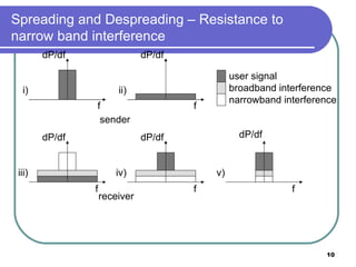
  • 10. Spreading and Despreading – Resistance to narrow band interference dP/df f i) dP/df f ii) sender dP/df f iii) dP/df f iv) receiver f v) user signal broadband interference narrowband interference dP/df
  • 11. Spreading and Despreading – Resistance to narrow band interference Original signal to be transmitted. The sender spreads the signal and converts the narrow-band signal to broadband (Power level can be much lower without losing data) During transmission, narrow and broadband noise gets added. The receiver despreads the given signal, narrow band interference is spread, leaving the broadband as it is. Receiver applies a band pass filter cutting off left & right of narrow band signal.
  • 12. Spreading and frequency selective fading frequency channel quality 1 2 3 4 5 6 narrow band signal guard space narrowband channels spread spectrum channels
  • 13. Problem with narrow band transmission (FDM) In the figure above, Frequencies 1,2 and 5 have reasonably good quality of service. Frequencies 3 & 4 are of very narrow band and they can get corrupted. Spread Spectrum can help in such a situation.
  • 14. How to fix the narrow band interference problem? 2 2 2 2 2 frequency channel quality 1 spread spectrum
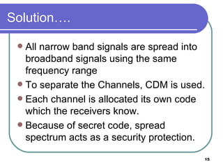
  • 15. Solution…. All narrow band signals are spread into broadband signals using the same frequency range To separate the Channels, CDM is used. Each channel is allocated its own code which the receivers know. Because of secret code, spread spectrum acts as a security protection.
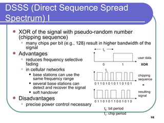
  • 16. DSSS (Direct Sequence Spread Spectrum) I XOR of the signal with pseudo-random number (chipping sequence) many chips per bit (e.g., 128) result in higher bandwidth of the signal Advantages reduces frequency selective fading in cellular networks base stations can use the same frequency range several base stations can detect and recover the signal soft handover Disadvantages precise power control necessary user data chipping sequence resulting signal 0 1 0 1 1 0 1 0 1 0 1 0 0 1 1 1 XOR 0 1 1 0 0 1 0 1 1 0 1 0 0 1 = t b t c t b : bit period t c : chip period
  • 17. Bandwidth of the resulting signal tc = Chip Period tb = Bit Period Spreading factor s -= tb/tc s*original bandwidth is the new bandwidth. It determines the BW of the resulting signal
  • 18. Spreading Factor Most civil applications need a spreading factor of 10 to 100. Military applications use a speeding factor of around 10,000.
  • 19. Barker Codes 10110111000 (802.11 wireless LANS) 11 110 1110 11101 1110010 1111100110101
  • 20. Barker Codes Let the code to be transmitted be 110. Let the Chip Barker Code be 10110111000 Hence the transmitted code is: 11111111111 11111111111 00000000000 XOR 10110111000 10110111000 10110111000 - 01001000111 01001000111 10110111000
  • 21. Barker Codes At the Receiver : The transmitted signal is XORed with the same chip sequence. 01001000111 01001000111 10110111000 XOR 10110111000 10110111000 10110111000 Resulting in : 11111111111 11111111111 00000000000 This is the original signal 110
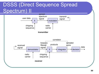
  • 22. DSSS (Direct Sequence Spread Spectrum) II X user data chipping sequence modulator radio carrier spread spectrum signal transmit signal transmitter demodulator received signal radio carrier X chipping sequence lowpass filtered signal receiver integrator products decision data sampled sums correlator
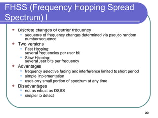
  • 23. FHSS (Frequency Hopping Spread Spectrum) I Discrete changes of carrier frequency sequence of frequency changes determined via pseudo random number sequence Two versions Fast Hopping: several frequencies per user bit Slow Hopping: several user bits per frequency Advantages frequency selective fading and interference limited to short period simple implementation uses only small portion of spectrum at any time Disadvantages not as robust as DSSS simpler to detect
  • 24. FHSS (Frequency Hopping Spread Spectrum) I user data slow hopping (3 bits/hop) fast hopping (3 hops/bit) 0 1 t b 0 1 1 t f f 1 f 2 f 3 t t d f f 1 f 2 f 3 t t d t b : bit period t d : dwell time
  • 25. FHSS Total available BW is split into many channels of smaller BWs Transmitter & Receiver stay in one of these channels and hop to another channel The implementation is a combination of FDM & TDM Hopping sequence defines the transition sequence amongst channels Dwell Time : Time spent on a channel with certain frequency The bandwidth of a frequency hopping signal is simply w times the number of frequency slots available, where w is the bandwidth of each hop channel.
  • 26. FHSS In Slow Hopping FHSS, one frequency is used for several bit periods In Fast Hopping FHSS, transmitter changes frequency several times during single bit transmission. Slow Hopping FHSS are not as immune to narrow band interference as the fast hopping FHSS.
  • 27. FHSS Transmitter and Receiver modulator user data hopping sequence modulator narrowband signal spread transmit signal transmitter received signal receiver demodulator data frequency synthesizer hopping sequence demodulator frequency synthesizer narrowband signal
  • 29. Distinctions Spreading is simpler in FHSS FHSS uses only a portion of the BW at any given time. DSSS are more resistant to fading and multi-path effects. DSSS signals are had to detect in the absence of the knowledge of spreading code.
  • 30. CELLULAR SYSTEMS Mobile systems using cells employ SDM A Base station covers a certain area and is called a cell. Coverage(Radii) of a cell : A few metres in buildings Hundreds of metres in cities Tens of kms on country side.
  • 31. Cell structure Implements space division multiplex: base station covers a certain transmission area (cell) Mobile stations communicate only via the base station Advantages of cell structures: higher capacity, higher number of users less transmission power needed more robust, decentralized base station deals with interference, transmission area etc. locally Problems: fixed network needed for the base stations handover (changing from one cell to another) necessary interference with other cells Cell sizes from some 100 m in cities to, e.g., 35 km on the country side (GSM) - even less for higher frequencies
  • 32. Frequency planning I Frequency reuse only with a certain distance between the base stations Standard model using 7 frequencies: Fixed frequency assignment: certain frequencies are assigned to a certain cell problem: different traffic load in different cells Dynamic frequency assignment: base station chooses frequencies depending on the frequencies already used in neighbor cells more capacity in cells with more traffic assignment can also be based on interference measurements f 4 f 5 f 1 f 3 f 2 f 6 f 7 f 3 f 2 f 4 f 5 f 1
  • 33. Frequency planning II f 4 f 5 f 1 f 3 f 2 f 6 f 7 f 3 f 2 f 4 f 5 f 1 f 3 f 5 f 6 f 7 f 2 f 2 3 cell cluster 7 cell cluster 3 cell cluster with 3 sector antennas f 1 f 2 f 3 f 2 f 1 f 1 f 2 f 3 f 2 f 3 f 1 f 2 f 1 f 3 f 3 f 3 f 3 f 3 f 1 f 1 f 1 f 2 f 3 f 2 f 3 f 2 f 3 h 1 h 2 h 3 g 1 g 2 g 3 h 1 h 2 h 3 g 1 g 2 g 3 g 1 g 2 g 3
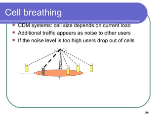
  • 34. Cell breathing CDM systems: cell size depends on current load Additional traffic appears as noise to other users If the noise level is too high users drop out of cells
  • 35. Cell A single cell in an analog cell-phone system uses one-seventh of the available duplex voice channels . A cell-phone carrier typically gets 832 radio frequencies to use in a city. Each cell phone uses two frequencies per call -- a duplex channel -- so there are typically 395 voice channels per carrier. (The other 42 frequencies are used for control channels -- more on this later.) The transmissions of a base station and the phones within its cell do not make it very far outside that cell. Therefore, in the figure above, both of the purple cells can reuse the same 56 frequencies. The same frequencies can be reused extensively across the city.
  • 36. Cell Each cell has about 56 voice channels available. In other words, in any cell, 56 people can be talking on their cell phone at one time. - Analog cellular systems(1G) Digital system(2G) using : TDMA : can carry three times as many calls as an analog system, so each cell has about 168 channels available.
  • 38. Borrowing Channel Allocation (BCA) Fixed allocation of frequency channels do not optimize channel usage, if the traffic pattern is varying . Cells with higher traffic pattern can borrow frequencies from its neighbors (which do not carry heavy traffic) This scheme is termed BCA.
  • 39. Dynamic Channel Allocation (DCA) Channels (frequencies) will be allocated dynamically. Frequencies can only be borrowed. The borrowed frequency can be blocked for the surrounding cells, to reduce interference