
![LC-3 Instruction (Recap)
› LC-3 has a four-bit opcode, bits [15:12] -- up to 16
different operations
› LC-3 has eight CPU registers. Registers are used as
operands for instructions -- each operand requires 3 bits
to specify which register
› Example: ADD instruction, opcode = 0001
“Add the contents of R2 (010) to the contents of R6 (110), and store the
result in R6 (110).”
3](https://image.slidesharecdn.com/lecture6-240913091947-6f0f845b/85/Lecture6-pdf-computer-architecture-for-computer-science-3-320.jpg)


![Addressing Modes
Register
› First operand is always specified by a register
› Second operand is a register if IR[5] = 0
Immediate
› If IR[5] = 1, the second operand is specified in the
instruction IR[4:0] is a 5-bit 2's complement integer,
sign-extended to 16 bits
9
Q: what are the min and max values that fit in IR[4:0]?](https://image.slidesharecdn.com/lecture6-240913091947-6f0f845b/85/Lecture6-pdf-computer-architecture-for-computer-science-9-320.jpg)


![LEA (not 100% operate)
› Computes an address by adding sign-extended IR[8:0] to PC, and
write the result to a register (Does not set condition codes)
14](https://image.slidesharecdn.com/lecture6-240913091947-6f0f845b/85/Lecture6-pdf-computer-architecture-for-computer-science-14-320.jpg)

![Data Movement Instructions: Load and Store
› Used to move data between memory and registers.
› LOAD = from memory to register (and sets condition codes)
› STORE = from register to memory
› Three variants of each, with different addressing modes:
PC-Relative Compute address by adding an offset
IR[8:0] to the PC
Indirect Load an address from a memory
location
Base+Offset Compute address by adding an offset
IR[5:0] to a register
16](https://image.slidesharecdn.com/lecture6-240913091947-6f0f845b/85/Lecture6-pdf-computer-architecture-for-computer-science-16-320.jpg)


![Indirect Addressing Mode
› With PC-relative mode, can only address data within 256
words of the instruction. What about the rest of memory?
› Solution #1: Read address from a memory location, then
load/store to that address
(1) Compute PC + IR[8:0] (just like PC-Relative), put in MAR
(2)Load from that address into MDR
(3)Move data from MDR into MAR
(4)Perform load/store
20](https://image.slidesharecdn.com/lecture6-240913091947-6f0f845b/85/Lecture6-pdf-computer-architecture-for-computer-science-20-320.jpg)


![BR
Remember that PC has
already been incremented
in Fetch phase.
PCMUX chooses either the
current PC if not taken, or
PC +offset if taken.
Logic: (IR[11] and N) or (IR[10] and Z) or (IR[9] and P)
29](https://image.slidesharecdn.com/lecture6-240913091947-6f0f845b/85/Lecture6-pdf-computer-architecture-for-computer-science-29-320.jpg)


![TRAP: Invoke a System Service Routine
› The TRAP instruction is used to give control to the operating
system to perform a task that user code is not allowed to do. The
details will be explained in Chapter 9
› For now, you just need to know that bits [7:0] hold a "trap vector"
-- a unique code that specifies the service routine. The service
routines used in this part of the course are:
trapvector service routine
x23 Input a character from the keyboard
x21 Output a character to the monitor
x25 Halt the processor
35](https://image.slidesharecdn.com/lecture6-240913091947-6f0f845b/85/Lecture6-pdf-computer-architecture-for-computer-science-35-320.jpg)


Lecture6.pdf computer architecture for computer science
- 1. Computer Architecture 2023-24 (WBCS010-05) Lecture 6: The LC-3 Reza Hassanpour [email protected]
- 2. Instruction (Recap) › A computer instruction is a binary value that specifies one operation to be carried out by the hardware. › Instruction is the fundamental unit of work. Once an instruction begins, it will complete its job. › Two components of an instruction: › opcode specifies the operation to be performed (for example: ADD) › operands specify the data to be used during the operation › The set of instructions and their formats is called the Instruction Set Architecture (ISA) of a computer 2
- 3. LC-3 Instruction (Recap) › LC-3 has a four-bit opcode, bits [15:12] -- up to 16 different operations › LC-3 has eight CPU registers. Registers are used as operands for instructions -- each operand requires 3 bits to specify which register › Example: ADD instruction, opcode = 0001 “Add the contents of R2 (010) to the contents of R6 (110), and store the result in R6 (110).” 3
- 4. Types of Instructions (Recap) › Instructions are classified into different types, depending on what sort of operation is specified › Operate › Will perform some sort of data transformation › Examples: add, AND, NOT, multiply, shift, … › Data Movement › Move data from memory to a register in the CPU, or › Move data from a register to a memory location › Control › Determine the next instruction to be executed 4
- 5. Control Instructions › Changes the PC to redirect program execution › Conditional Branch: BR › Unconditional Branch: JMP › Subroutines and System Calls: • JSR, JSRR, TRAP, RET, RTI (Discussed in Chapters 8 and 9) 5
- 6. Condition Codes › LC-3 has three condition code registers › N = negative (less than zero) › Z = zero › P = positive (greater than zero) › Set by instructions that compute or load a value into a register › ADD, AND, NOT, LD, LDI, LDR › Based on result of computation or load. Other instructions do not change the condition codes. › Exactly one of these will be set (1). Others will be zero. 6
- 7. Instruction Type 1 Operate Instructions
- 8. Operate Instructions ADD › Add two integers and write the result to a register › Set condition codes AND › Perform a bitwise AND operation on two integers, and write the result to a register › Set condition codes NOT › Perform a bitwise NOT on an integer, and write the result to a register › Set condition codes LEA › Add an offset to the PC and write the result to a register 8
- 9. Addressing Modes Register › First operand is always specified by a register › Second operand is a register if IR[5] = 0 Immediate › If IR[5] = 1, the second operand is specified in the instruction IR[4:0] is a 5-bit 2's complement integer, sign-extended to 16 bits 9 Q: what are the min and max values that fit in IR[4:0]?
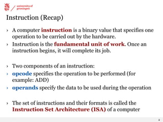
- 10. ADD/AND (Register mode) this zero means “register mode” Sets condition codes 10
- 11. ADD/AND (Immediate mode) this one means “immediate mode” Sets condition codes 11
- 12. NOT (Register mode) Sets condition codes 12
- 13. Only ADD, AND, and NOT? › It might seem very limiting to only provide these three operations, but anything else can be built from these • Negate -- Flip bits with NOT, then ADD +1 • Subtract -- Negate and ADD • Multiply -- Repeated additions • OR -- Use DeMorgan's Law (see Chapter 2) • Clear -- AND with 0 to set register to zero • Copy -- ADD 0 (zero) to copy from one register (src) to another (dst) • Others: XOR, divide, shift left, increment, ... 13
- 14. LEA (not 100% operate) › Computes an address by adding sign-extended IR[8:0] to PC, and write the result to a register (Does not set condition codes) 14
- 15. Instruction Type 2 Data Movement Instructions
- 16. Data Movement Instructions: Load and Store › Used to move data between memory and registers. › LOAD = from memory to register (and sets condition codes) › STORE = from register to memory › Three variants of each, with different addressing modes: PC-Relative Compute address by adding an offset IR[8:0] to the PC Indirect Load an address from a memory location Base+Offset Compute address by adding an offset IR[5:0] to a register 16
- 17. PC-Relative Addressing Mode › Wants to specify address directly in the instruction. • But an address is 16 bits, and so is an instruction! • After subtracting 4 bits for opcode and 3 bits for register, we have 9 bits available for address. › Solution: Use the 9 bits as a signed offset from the current PC. › Can form any address X, such that: PC − 256 ≤ X ≤ PC + 255 › Remember that PC is incremented as part of the FETCH phase; › This is done before the EVALUATE ADDRESS stage. 17 So the range is -255 … +256 locations relative to the LD/ST. Do you see it?
- 18. LD (PC-Relative mode) Sets condition codes 18
- 20. Indirect Addressing Mode › With PC-relative mode, can only address data within 256 words of the instruction. What about the rest of memory? › Solution #1: Read address from a memory location, then load/store to that address (1) Compute PC + IR[8:0] (just like PC-Relative), put in MAR (2)Load from that address into MDR (3)Move data from MDR into MAR (4)Perform load/store 20
- 21. LDI (Indirect mode) Sets condition codes 21
- 23. Base + Offset Addressing Mode › With PC-relative mode, can only address data within 256 words of the instruction. What about the rest of memory? › Solution #2: Use a register to generate a full 16-bit address › 4 bits for opcode, 3 for src/dest register, 3 bits for base register -- the one to be used as an address. › Remaining 6 bits are used as a signed offset. • Offset is sign-extended before adding to base register. Offset is often zero, but a non-zero offset can be useful at times. 23
- 24. LDR (Base + Offset mode) Sets condition codes 24
- 25. STR (Base + Offset mode) 25
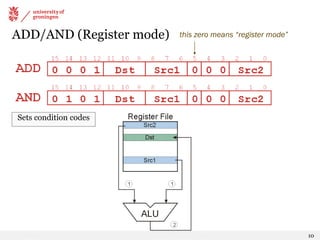
- 26. Example using Load/Store Addressing Modes opcode 26 LEA ADD ST AND ADD STR LDI
- 27. Instruction Type 3 Control Instructions
- 28. Conditional Branch (BR) › BR specifies two things: • Condition -- if true, branch is taken (PC changed to target address) if false, branch is not taken (PC not changed) • Target address › Condition specifies which condition code bits are relevant for this branch If any specified bit is set, branch is taken. › Example: BRn = branch if N bit is set Example: BRnp = branch if N or P bit is set › Target is specified using PC-Relative mode 28
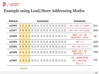
- 29. BR Remember that PC has already been incremented in Fetch phase. PCMUX chooses either the current PC if not taken, or PC +offset if taken. Logic: (IR[11] and N) or (IR[10] and Z) or (IR[9] and P) 29
- 30. Example BR instruction › Suppose the following instruction is fetched from address x4027 › Condition: z Branch will be taken if Z bit is set › Target: x4028 + x00D9 = x4101 › Current PC is x4028, because it was incremented when fetching If branch is taken PC will be x4101 If branch is not taken PC will remain x4028 30
- 31. Example: Loop with a Counter › Compute the sum of 12 integers stored in x3100 - x310B Instructions begin at address x3000 › R2 counts down from 12. Branch out of the loop when R2 becomes zero 31
- 32. Example: Loop with Sentinel › Compute the sum of integers starting at x3100, until a negative integer is found. Instructions start at x3000 › In this case, it's the data that tells when to exit the loop. When the value loaded into R4 is negative, take branch to x3008 32
- 33. Unconditional Branch (JMP) › We can create a branch that is always taken by setting n, z, and p to 1 › However, the target address of BR is limited by the 9-bit PC offset › The JMP instruction provides an unconditional branch to any target location by using the contents of a register as the target address. It simply copies the register into the PC 33
- 35. TRAP: Invoke a System Service Routine › The TRAP instruction is used to give control to the operating system to perform a task that user code is not allowed to do. The details will be explained in Chapter 9 › For now, you just need to know that bits [7:0] hold a "trap vector" -- a unique code that specifies the service routine. The service routines used in this part of the course are: trapvector service routine x23 Input a character from the keyboard x21 Output a character to the monitor x25 Halt the processor 35
- 36. Input / Output Service Routines › Getting character input from the keyboard • TRAP x23 is used to invoke the keyboard input service routine. • When the OS returns control to our program, the ASCII code for the key pressed by the user will be in R0. › Sending character output to the monitor • TRAP x21 is used to invoke the monitor output service routine. • Before invoking the routine, put the ASCII character to be output into R0. 36
- 37. Example Program: Count Occurrences of a Character › We want to count the number of times a user-specified character appears in a text file, and then print the count to the monitor • The text file is stored in memory as a sequence of ASCII characters • The end of the file is denoted with the EOT* character (x04). NOTE: We do not know how many characters are in the file; EOT is the sentinel value that signals when we are done • A pointer to the file will be stored at the end of the program. (A "pointer" is a memory address; it will be the address of the first character in the file) • We will assume that the character will appear no more than 9 times • Program instructions will start at x3000. The file data can be anywhere in memory 37 * End Of Transmission
- 38. Part 1: Initializing Registers R2 is counter. R3 is address of first character to read from file. R0 is character from keyboard. R1 is first character from file. 38
- 39. Part 2: Read Characters and Count Compare character to immediate x04 (EOT in ASCII). If equal, exit loop. Otherwise, count if matches user input and read the next character. 39
- 40. Part 3: Output Count and HALT When loop is finished, convert count (R2) to the corresponding ASCII character by adding '0' (x30). Output the character and halt the program 40
- 41. Questions?