SlideShare a Scribd company logo
Basics of Sequential Circuits,
Types & Their Working
A Sequential logic circuit is a form of the binary circuit; its design employs
one or more inputs and one or more outputs, whose states are related to
some definite rules that depend on previous states. Both the inputs and
outputs can reach either of the two states: logic 0 (low) or logic 1 (high). In
these circuits, their output depends not only on the combination of the logic
states at its inputs but moreover on the logic states that existed previously. In
other words, their output depends on a SEQUENCE of the events occurring at
the circuit inputs. Examples of such circuits include clocks, flip-flops, bi-
stables, counters, memories, and registers. The actions of the sequential
circuits depend on the range of basic sub-circuits.
What is a Sequential Logic Circuit?
A sequential circuit is a logical circuit, where the output depends on the
present value of the input signal as well as the sequence of past inputs. While
a combinational circuit is a function of present input only. A sequential circuit is
a combination of a combinational circuit and a storage element. the sequential
circuits use current input variables and previous input variables which are
stored and provide the data to the circuit on the next clock cycle.
Design Procedure of Sequential Logic Circuits
1. This procedure involves the following steps
2. First, derive the state diagram
3. Take as the state table or an equivalence representation, such as a state
diagram.
4. The number of states may be reduced by the state reduction technique
5. Verify the number of flip-flops needed
6. Choose the type of flip-flops to be used
7. Derive excitation equations
8. Using the map or some other simplification method, derive the output
function and the flip-flop input functions.
9. Draw a logic diagram or a list of Boolean functions from which a logic
diagram can be obtained.
Categories of Sequential Logic Circuits
Sequential logic circuits are divided into three categories like following.
 Event-Driven
 Clock Driven
 Pulse Driven
Event-Driven: Asynchronous circuits that can change the state immediately
when enabled. Asynchronous (fundamental mode) sequential circuit: The
behavior is dependent on the arrangement of the input signal that changes
continuously over time, and the output can be changed at any time (clock
less).Clock Driven: Synchronous circuits that are synchronized to a specific
clock signal. Synchronous (latch mode) sequential circuit: The behavior can
be defined from the knowledge of circuits that achieve synchronization by
using a timing signal called the clock.
Pulse Driven: This is a mixture of the two that responds to the triggering
pulses.
Types of Sequential Circuits
The sequential circuits are classified into two types
 Synchronous Circuit
 Asynchronous Circuit
In synchronous sequential circuits, the state of the device changes at discrete
times in response to a clock signal. In asynchronous circuits, the state of the
device changes in response to changing inputs.
Synchronous Circuits
In synchronous circuits, the inputs are pulses with certain restrictions on pulse
width and propagation delay. Thus synchronous circuits can be divided into
clocked and un-clocked or pulsed sequential circuits.
Synchronous Circuit
Clocked Sequential Circuit
The clocked sequential circuits have flip-flops or gated latches for its memory
elements. There is a periodic clock connected to the clock inputs of all the
memory elements of the circuit to synchronize all the internal changes of
state. Hence the operation of the circuit is controlled and synchronized by the
periodic pulse of the clock.
Cocked Sequential
Unlocked Sequential Circuit
An unlocked sequential circuit requires two consecutive transitions between 0
and 1 to alternate the state of the circuit. An unlocked mode circuit is designed
to respond to pulses of certain durations which do not affect the circuit’s
behavior.
UnClocked Sequential
The synchronous logic circuit is very simple. The logic gates which perform the
operations on the data, require a finite amount of time to respond to the
changes in the input.
Asynchronous Circuits
An asynchronous circuit does not have a clock signal to synchronize its
internal changes of the state. Hence the state change occurs in direct
response to changes that occur in primary input lines. An asynchronous circuit
does not require precise timing control from flip-flops.
Asynchronous Circuit
Asynchronous logic is more difficult to design and it has some problems
compared to synchronous logic. The main problem is that the digital memory
is sensitive to the order that their input signals arrive them, like, if two signals
arrive at a flip-flop at the same time, which state the circuit goes into can
depend on which signal gets to the logic gate first.
Asynchronous circuits are used in critical parts of synchronous systems where
the speed of the system is a priority, like in microprocessors and digital signal
processing circuits.
Flip Flop Circuit
A flip-flop is a sequential circuit that samples the input and changes the output
at a particular instance of time. It has two stable states and can be used to
store state information. Signals are applied to one or more control inputs to
change the state of the circuit and will have one or two outputs.
It is the basic storage element in sequential logic and fundamental building
blocks of digital electronic systems. They can be used to keep a record of the
value of a variable. Flip-flop is also used to control the functionality of a circuit.
RS Flip Flop
The R-S flip-flop is the simplest flip-flop. It has two outputs, one output is the
reverse of the other, and two inputs. The two inputs are Set and Reset. The
flip-flop basically uses NAND gates with an additional enable pin. The circuit
gives output only when the enable pin is high.
Block Diagram
SR Flip Flop Block
Diagram
Circuit Diagram
SR Flip Flop
Circuit Diagram
SR Flip Flop Truth Table
SR Flip Flop Truth
Table
JK Flip Flop
JK flip-flop is one of the important flip-flops. If the J and K inputs are one and
when the clock is applied, the output changes regardless of past conditions. If
the J and K inputs are 0 and when the clock is applied, there will be no
change in the output. There is no indeterminate condition in the JK flip-flop.
Circuit Diagram
JK Flip Flop Circuit
JK Flip Flop Truth Table
JK Flip
Flop Truth Table
D Flip Flop
D flip-flop has a single data line and a clock input. The D flip-flop is the
simplification of an SR flip-flop. The input of the D flip-flop goes directly to the
input S and the compliment goes to input R. D input is sampled throughout the
clock pulse.
Circuit Diagram
D
flip flop Circuit
D flip flop Truth Table
D flip flop Truth
Table
T Flip Flop
It is a method of avoiding indeterminate state found in the process of an RS
flip-flop. It is to provide only one input, i.e. T input. This flip-flop acts as a
Toggle switch. Toggle means to change to another state. T flip-flop is
designed from clocked RS flip-flop.
Circuit Diagram
T Flip Flop Circuit
T Flip Flop Truth Table
T Flip Flop Truth
Table
Electronic Oscillator
An electronic oscillator is an electronic circuit that produces periodic,
oscillating signals. An oscillator converts direct current from a power supply to
an alternating current signal.
Electronic Oscillator
An oscillator is an amplifier that provides feedback with an input signal. It is a
non-rotating device to produce alternating current. Enough power must be fed
back to the input circuit for the oscillator to drive itself. The feedback signal in
the oscillator is regenerative.
Electronic oscillators are classified into two categories
 Sinusoidal or Harmonic Oscillator
 Non-sinusoidal or Relaxation Oscillator
Sinusoidal or Harmonic Oscillator
The oscillators that give output as a sine wave are called sinusoidal
oscillators. These oscillators can provide the output at frequencies ranging
from 20Hz to GHz. Depending on the material or components used in the
oscillator, Sinusoidal oscillators are further classified into four types
 Tuned Circuit Oscillator
 RC Oscillator
 Crystal Oscillator
 Negative Resistance Oscillator
Non-Sinusoidal or Relaxation Oscillator
Non-sinusoidal oscillators provide output in the form of a square, rectangular
or sawtooth waveform. These oscillators can provide an output at frequencies
ranging from 0 to 20MHz.
Examples of Sequential Logic Circuits
The examples of sequential logic circuits are discussed below.
Clocks
State changes of most sequential circuits occur at times specified by free-
running clock signals. As the name implies, sequential logic circuits require a
means by which events can be sequenced.
Clock Sequential Circuit
The state changes are controlled by the clocks. A “clock” is a special circuit
that sends pulses with accurate pulse width and an accurate interval between
consecutive pulses. The interval between consecutive pulses is called the
clock cycle time. The Clock speed is normally measured in Megahertz or
Gigahertz.
Flip-Flops
The basic building block of the combinational circuit has logic gates, while
indeed the basic building block of a sequential circuit is a flip-flop. Flip-flop has
a better and greater usage in shift register, counters and memory devices. It is
a storage device capable of storing one bit of data. Flip flop has two inputs
and two outputs labeled as Q and Q’. It is normal and complements.
Flip Flops
Bi-Stables
In most cases, the bi-stables are indicated by a box or circle. Lines in or
around bi-stables not only mark them as bi-stables but also indicate how they
function. Bi-stables are of two types latch and flip flop. The bi-stables have
two stable states one is SET and the other one is RESET. They can retain
either of these stages indefinitely, which makes them useful for storage
purposes. Latches and flip-flops are different in the way they change from one
state to another.
Bi-stable input and output
Waveforms
Counters
A counter is a register that goes throughout a predetermined sequence of
states upon the application of clock pulses. From another viewpoint, a counter
is some sort of sequential circuit whose state diagram is a single cycle. In
other words, counters are a particular case of a finite state machine. The
output is generally a state value.
Basic Counter
Circuit
There are two types of counters: Asynchronous counters (Ripple counter) and
the other one is Synchronous counters. The asynchronous counter is the
clock signal (CLK), which is simply used to clock the first FF. Each FF (except
the first FF) is clocked by the preceding FF. The synchronous counter is the
clock signal (CLK) that is functional to all FF, which means that all FF shares
the same clock signal. Thus, the output changes at the same time.
Registers
Registers are clocked sequential circuits. A register is a collection of flip-flops;
each flip-flop is capable of storing one bit of information. An n-bit register
consists of n flip-flops and is capable of storing n bits of information. Besides
flip-flops, a register usually contains a combinational logic to perform some
simple tasks. The flip-flops hold binary information.The gates to determine
how the information is shifted into the register. Counters are a special type of
register. A counter goes through a predetermined sequence of states.
Register Circuit
Memories
Memory elements can be anything that creates a past value available at some
future time-devices that can behold a binary value. Memory elements are
typically flip-flops. Memory output which is considered as a circuit’s “current
state” is a numerical label. The state embodies all the information about the
past needed to define the current output.
Differences between the Combinational and Sequential Logic Circuits
The difference between the combinational and sequential logic circuits is
listed below.
Combinational circuits Sequential circuits
The circuit whose output, at any immediate time, depends
only on the input present at that instant only is known as a
combinational circuit.
The circuit whose output at any immediat
not only on the input present but also on t
output, is known as sequential circuit
These types of circuits have no memory unit.
These types of circuits have a memory un
past output.
It is Faster. It is Slower.
These are easy to design. These are difficult to design.
Examples of combinational circuits are a half adder, full
adder, magnitude comparator, multiplexer, demultiplexer,
etc.
Examples of sequential circuits are flip-fl
counter, clocks, etc.
Applications
The major applications of a Sequential Logic Circuits are,
 As a counter, shift register, flip-flops.
 Used to build the memory unit.
 As programmable devices (PLDs, FPGA, CPLDs)
This is all about an overview of the sequential logic circuits. The sequential
circuits are the circuits, where the immediate value of outputs depends on the
immediate values of inputs and also on states they were in previously. They
contain memory blocks for storing the previous state of the circuit.
Furthermore, any queries regarding this article or any help in implementing
electrical and electronics projects, you can approach us by commenting in the
comment section below. Here is a question for you, What is meant by
sequential circuits?
SHARE THIS POST:

Facebook

Twitter
 Google+

LinkedIn

Pinterest
Post navigation
‹ PREVIOUSFM Remote Encoder/Decoder Circuit Working Principle and Applications
NEXT ›How to Interface an LED With 8051 Microcontroller
RELATED CONTENT
Amplifier Distortion : Circuit, Types, How to Reduce and Vs Distortion Pedals
Corner Reflector : Working, Types, Calculation, radiation pattern & Its Applications
Resistor Transistor Logic : Circuit, Working, Differences, Characteristics & Its Applications
Voltage Amplifier : Circuit, Voltage Gain, Vs PowerAmplifier & Its Applications
RECENT POSTS
 Amplifier Distortion : Circuit, Types, How to Reduce and Vs Distortion Pedals
 Corner Reflector : Working, Types, Calculation, radiation pattern & Its Applications
 Resistor Transistor Logic : Circuit, Working, Differences, Characteristics & Its Applications
 Plug Flow Reactor : Working, Derivation, Characteristics & Its Applications
 Voltage Amplifier : Circuit, Voltage Gain, Vs PowerAmplifier & Its Applications
 Space Division Multiplexing : Diagram, Working, Advantages, Disadvantages & Its Applications
 Vacuum Tube Amplifier : Circuit, Working, Types, vs Digital Amplifier & Its Applications
PROJECTS
 555 Timer Circuits (6)
 8051 Projects (60+)
 Arduino Projects (40+)
 ARM Projects (100+)
 Communication Projects (140+)
 DTMF Projects (25+)
 ECE Projects (400+)
 EEE Projects (240+)
 EIE Projects (100+)
 Electrical Mini Projects (120+)
 Electrical Project Ideas (300+)
 Electronics Projects (160+)
 Embedded Projects (200+)
 GSM Projects (100+)
 Home Automation Projects (100+)
 IOT Projects (30)
 LabView Projects (100+)
 Matlab Projects (190+)
 Microcontroller Mini Projects (80+)
 Mini Project Circuits (20+)
 Mini Project Ideas (45+)
 PIC Projects (30+)
 Power Electronics Projects (45+)
 Raspberry Pi Projects (9)
 RFID Projects (70+)
 Robotics Projects (100+)
 Sensor Projects (40+)
 Solar Projects (150+)
 VLSI Projects (180+)
 Wireless Projects (100+)
 Zigbee Projects (120+)
CATEGORIES
 Communication
 Electrical
 Electronics
 Project Ideas
 Robotics
 Technology
RECENT COMMENTS
 K BALAJI on Simple Electronic Circuits for Beginners
 Anny Arbert on Gyroscope Sensor Working and Its Applications
 Abhuday dangi on What is a UJT Relaxation Oscillator – Circuit Diagram and Applications
 Satyadeo Vyas on Construction and Working of a 4 Point Starter
FOLLOW ON FACEBOOK
<="" img="" style="box-sizing: border-box; border:
0px; vertical-align: middle; max-width: 100%;">
 Advertise With Us
 Disclaimer
 Report Violation
 Image Usage Policy
 Privacy Policy
 Contact Us
Copyright 2013 - 2024 © Elprocus

More Related Content

Similar to logic Basics of Sequential Circuits.docx (20)

PPT
Sequential_DigitalLogicSecCSeqCkts__.ppt
NayanjyotSingh
 
PPTX
Chapter 6: Sequential Logic
Er. Nawaraj Bhandari
 
PDF
FYBSC IT Digital Electronics Unit IV Chapter II Sequential Circuits- Flip-Flops
Arti Parab Academics
 
PPT
PPT 2nd unit course file.ppt
SILAMBARASANAECEKIOT
 
PPTX
Unit 4 sequential circuits
AmrutaMehata
 
PDF
Report on Sequential circuit by Appiah Kubi Bright
Appiah Kubi Bright
 
PPTX
unit 5.pptx
ssuser022fec
 
PPTX
Flip flop
Bhaskar Kumar Jha
 
PPTX
Sequential logic circuit
AswiniT3
 
PPTX
5.Digital Logic Design (Chap 06, Topic 11,12,13,14,15,16,17- Sequential Circu...
aavnaf
 
PPT
flip flop 13.ppt
SivaranjaniN6
 
PPTX
De EE unit-3.pptx
MukulThory1
 
PPTX
UNIT - III.pptx
amudhak10
 
DOCX
All flipflop
DHEERAJ CHOKSE
 
PPTX
Introduction to flipflops basic of elctronics COA.pptx
Saini71
 
PDF
Lec 06 - Synchronous Sequential Logic
Vajira Thambawita
 
PPTX
DIGITAL ELECTRONICS: UNIT-III SYNCHRONOUS SEQUENTIAL CIRCUITS
Sridhar191373
 
PPTX
Sequential Circuitsdddddddddddddddddsssssssssss-ppt.pptx
AhmedAlAfandi5
 
PDF
Sequential Circuits-ppt_2.pdf
imadshaheen2
 
PPTX
ilide.info-flip-flops-and-application-japan-malaysia-technical-institute-jmti...
TanmoyBanerjee44
 
Sequential_DigitalLogicSecCSeqCkts__.ppt
NayanjyotSingh
 
Chapter 6: Sequential Logic
Er. Nawaraj Bhandari
 
FYBSC IT Digital Electronics Unit IV Chapter II Sequential Circuits- Flip-Flops
Arti Parab Academics
 
PPT 2nd unit course file.ppt
SILAMBARASANAECEKIOT
 
Unit 4 sequential circuits
AmrutaMehata
 
Report on Sequential circuit by Appiah Kubi Bright
Appiah Kubi Bright
 
unit 5.pptx
ssuser022fec
 
Sequential logic circuit
AswiniT3
 
5.Digital Logic Design (Chap 06, Topic 11,12,13,14,15,16,17- Sequential Circu...
aavnaf
 
flip flop 13.ppt
SivaranjaniN6
 
De EE unit-3.pptx
MukulThory1
 
UNIT - III.pptx
amudhak10
 
All flipflop
DHEERAJ CHOKSE
 
Introduction to flipflops basic of elctronics COA.pptx
Saini71
 
Lec 06 - Synchronous Sequential Logic
Vajira Thambawita
 
DIGITAL ELECTRONICS: UNIT-III SYNCHRONOUS SEQUENTIAL CIRCUITS
Sridhar191373
 
Sequential Circuitsdddddddddddddddddsssssssssss-ppt.pptx
AhmedAlAfandi5
 
Sequential Circuits-ppt_2.pdf
imadshaheen2
 
ilide.info-flip-flops-and-application-japan-malaysia-technical-institute-jmti...
TanmoyBanerjee44
 

Recently uploaded (20)

PPTX
apidays Singapore 2025 - Designing for Change, Julie Schiller (Google)
apidays
 
PDF
AUDITABILITY & COMPLIANCE OF AI SYSTEMS IN HEALTHCARE
GAHI Youssef
 
PPTX
apidays Munich 2025 - Building an AWS Serverless Application with Terraform, ...
apidays
 
PPTX
ER_Model_with_Diagrams_Presentation.pptx
dharaadhvaryu1992
 
PDF
JavaScript - Good or Bad? Tips for Google Tag Manager
📊 Markus Baersch
 
PDF
R Cookbook - Processing and Manipulating Geological spatial data with R.pdf
OtnielSimopiaref2
 
PDF
Context Engineering for AI Agents, approaches, memories.pdf
Tamanna
 
PDF
The European Business Wallet: Why It Matters and How It Powers the EUDI Ecosy...
Lal Chandran
 
PDF
Early_Diabetes_Detection_using_Machine_L.pdf
maria879693
 
PDF
apidays Helsinki & North 2025 - Monetizing AI APIs: The New API Economy, Alla...
apidays
 
PPTX
Advanced_NLP_with_Transformers_PPT_final 50.pptx
Shiwani Gupta
 
PPTX
Dr djdjjdsjsjsjsjsjsjjsjdjdjdjdjjd1.pptx
Nandy31
 
PPTX
Exploring Multilingual Embeddings for Italian Semantic Search: A Pretrained a...
Sease
 
PDF
Product Management in HealthTech (Case Studies from SnappDoctor)
Hamed Shams
 
PDF
apidays Helsinki & North 2025 - REST in Peace? Hunting the Dominant Design fo...
apidays
 
PDF
OOPs with Java_unit2.pdf. sarthak bookkk
Sarthak964187
 
PDF
Building Production-Ready AI Agents with LangGraph.pdf
Tamanna
 
PDF
Copia de Strategic Roadmap Infographics by Slidesgo.pptx (1).pdf
ssuserd4c6911
 
PDF
Avatar for apidays apidays PRO June 07, 2025 0 5 apidays Helsinki & North 2...
apidays
 
PPTX
apidays Helsinki & North 2025 - Running a Successful API Program: Best Practi...
apidays
 
apidays Singapore 2025 - Designing for Change, Julie Schiller (Google)
apidays
 
AUDITABILITY & COMPLIANCE OF AI SYSTEMS IN HEALTHCARE
GAHI Youssef
 
apidays Munich 2025 - Building an AWS Serverless Application with Terraform, ...
apidays
 
ER_Model_with_Diagrams_Presentation.pptx
dharaadhvaryu1992
 
JavaScript - Good or Bad? Tips for Google Tag Manager
📊 Markus Baersch
 
R Cookbook - Processing and Manipulating Geological spatial data with R.pdf
OtnielSimopiaref2
 
Context Engineering for AI Agents, approaches, memories.pdf
Tamanna
 
The European Business Wallet: Why It Matters and How It Powers the EUDI Ecosy...
Lal Chandran
 
Early_Diabetes_Detection_using_Machine_L.pdf
maria879693
 
apidays Helsinki & North 2025 - Monetizing AI APIs: The New API Economy, Alla...
apidays
 
Advanced_NLP_with_Transformers_PPT_final 50.pptx
Shiwani Gupta
 
Dr djdjjdsjsjsjsjsjsjjsjdjdjdjdjjd1.pptx
Nandy31
 
Exploring Multilingual Embeddings for Italian Semantic Search: A Pretrained a...
Sease
 
Product Management in HealthTech (Case Studies from SnappDoctor)
Hamed Shams
 
apidays Helsinki & North 2025 - REST in Peace? Hunting the Dominant Design fo...
apidays
 
OOPs with Java_unit2.pdf. sarthak bookkk
Sarthak964187
 
Building Production-Ready AI Agents with LangGraph.pdf
Tamanna
 
Copia de Strategic Roadmap Infographics by Slidesgo.pptx (1).pdf
ssuserd4c6911
 
Avatar for apidays apidays PRO June 07, 2025 0 5 apidays Helsinki & North 2...
apidays
 
apidays Helsinki & North 2025 - Running a Successful API Program: Best Practi...
apidays
 
Ad

logic Basics of Sequential Circuits.docx

  • 1. Basics of Sequential Circuits, Types & Their Working A Sequential logic circuit is a form of the binary circuit; its design employs one or more inputs and one or more outputs, whose states are related to some definite rules that depend on previous states. Both the inputs and outputs can reach either of the two states: logic 0 (low) or logic 1 (high). In these circuits, their output depends not only on the combination of the logic states at its inputs but moreover on the logic states that existed previously. In other words, their output depends on a SEQUENCE of the events occurring at the circuit inputs. Examples of such circuits include clocks, flip-flops, bi- stables, counters, memories, and registers. The actions of the sequential circuits depend on the range of basic sub-circuits. What is a Sequential Logic Circuit? A sequential circuit is a logical circuit, where the output depends on the present value of the input signal as well as the sequence of past inputs. While a combinational circuit is a function of present input only. A sequential circuit is a combination of a combinational circuit and a storage element. the sequential circuits use current input variables and previous input variables which are stored and provide the data to the circuit on the next clock cycle. Design Procedure of Sequential Logic Circuits 1. This procedure involves the following steps 2. First, derive the state diagram 3. Take as the state table or an equivalence representation, such as a state diagram. 4. The number of states may be reduced by the state reduction technique 5. Verify the number of flip-flops needed 6. Choose the type of flip-flops to be used 7. Derive excitation equations 8. Using the map or some other simplification method, derive the output function and the flip-flop input functions. 9. Draw a logic diagram or a list of Boolean functions from which a logic diagram can be obtained. Categories of Sequential Logic Circuits
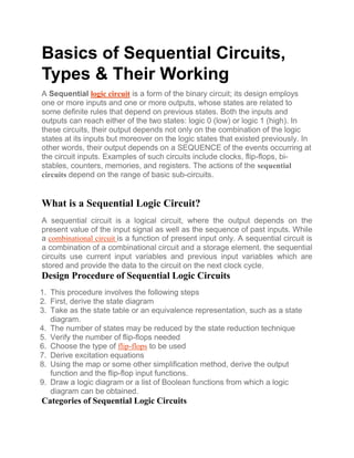
  • 2. Sequential logic circuits are divided into three categories like following.  Event-Driven  Clock Driven  Pulse Driven Event-Driven: Asynchronous circuits that can change the state immediately when enabled. Asynchronous (fundamental mode) sequential circuit: The behavior is dependent on the arrangement of the input signal that changes continuously over time, and the output can be changed at any time (clock less).Clock Driven: Synchronous circuits that are synchronized to a specific clock signal. Synchronous (latch mode) sequential circuit: The behavior can be defined from the knowledge of circuits that achieve synchronization by using a timing signal called the clock. Pulse Driven: This is a mixture of the two that responds to the triggering pulses. Types of Sequential Circuits The sequential circuits are classified into two types  Synchronous Circuit  Asynchronous Circuit In synchronous sequential circuits, the state of the device changes at discrete times in response to a clock signal. In asynchronous circuits, the state of the device changes in response to changing inputs. Synchronous Circuits In synchronous circuits, the inputs are pulses with certain restrictions on pulse width and propagation delay. Thus synchronous circuits can be divided into clocked and un-clocked or pulsed sequential circuits.
  • 3. Synchronous Circuit Clocked Sequential Circuit The clocked sequential circuits have flip-flops or gated latches for its memory elements. There is a periodic clock connected to the clock inputs of all the memory elements of the circuit to synchronize all the internal changes of state. Hence the operation of the circuit is controlled and synchronized by the periodic pulse of the clock. Cocked Sequential Unlocked Sequential Circuit An unlocked sequential circuit requires two consecutive transitions between 0 and 1 to alternate the state of the circuit. An unlocked mode circuit is designed to respond to pulses of certain durations which do not affect the circuit’s behavior.
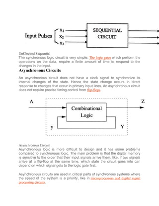
  • 4. UnClocked Sequential The synchronous logic circuit is very simple. The logic gates which perform the operations on the data, require a finite amount of time to respond to the changes in the input. Asynchronous Circuits An asynchronous circuit does not have a clock signal to synchronize its internal changes of the state. Hence the state change occurs in direct response to changes that occur in primary input lines. An asynchronous circuit does not require precise timing control from flip-flops. Asynchronous Circuit Asynchronous logic is more difficult to design and it has some problems compared to synchronous logic. The main problem is that the digital memory is sensitive to the order that their input signals arrive them, like, if two signals arrive at a flip-flop at the same time, which state the circuit goes into can depend on which signal gets to the logic gate first. Asynchronous circuits are used in critical parts of synchronous systems where the speed of the system is a priority, like in microprocessors and digital signal processing circuits.
  • 5. Flip Flop Circuit A flip-flop is a sequential circuit that samples the input and changes the output at a particular instance of time. It has two stable states and can be used to store state information. Signals are applied to one or more control inputs to change the state of the circuit and will have one or two outputs. It is the basic storage element in sequential logic and fundamental building blocks of digital electronic systems. They can be used to keep a record of the value of a variable. Flip-flop is also used to control the functionality of a circuit. RS Flip Flop The R-S flip-flop is the simplest flip-flop. It has two outputs, one output is the reverse of the other, and two inputs. The two inputs are Set and Reset. The flip-flop basically uses NAND gates with an additional enable pin. The circuit gives output only when the enable pin is high. Block Diagram SR Flip Flop Block Diagram Circuit Diagram SR Flip Flop Circuit Diagram SR Flip Flop Truth Table
  • 6. SR Flip Flop Truth Table JK Flip Flop JK flip-flop is one of the important flip-flops. If the J and K inputs are one and when the clock is applied, the output changes regardless of past conditions. If the J and K inputs are 0 and when the clock is applied, there will be no change in the output. There is no indeterminate condition in the JK flip-flop. Circuit Diagram
  • 7. JK Flip Flop Circuit JK Flip Flop Truth Table JK Flip Flop Truth Table D Flip Flop D flip-flop has a single data line and a clock input. The D flip-flop is the simplification of an SR flip-flop. The input of the D flip-flop goes directly to the input S and the compliment goes to input R. D input is sampled throughout the clock pulse.
  • 8. Circuit Diagram D flip flop Circuit D flip flop Truth Table D flip flop Truth Table T Flip Flop It is a method of avoiding indeterminate state found in the process of an RS flip-flop. It is to provide only one input, i.e. T input. This flip-flop acts as a Toggle switch. Toggle means to change to another state. T flip-flop is designed from clocked RS flip-flop. Circuit Diagram
  • 9. T Flip Flop Circuit T Flip Flop Truth Table T Flip Flop Truth Table Electronic Oscillator An electronic oscillator is an electronic circuit that produces periodic, oscillating signals. An oscillator converts direct current from a power supply to an alternating current signal.
  • 10. Electronic Oscillator An oscillator is an amplifier that provides feedback with an input signal. It is a non-rotating device to produce alternating current. Enough power must be fed back to the input circuit for the oscillator to drive itself. The feedback signal in the oscillator is regenerative. Electronic oscillators are classified into two categories  Sinusoidal or Harmonic Oscillator  Non-sinusoidal or Relaxation Oscillator Sinusoidal or Harmonic Oscillator The oscillators that give output as a sine wave are called sinusoidal oscillators. These oscillators can provide the output at frequencies ranging from 20Hz to GHz. Depending on the material or components used in the oscillator, Sinusoidal oscillators are further classified into four types  Tuned Circuit Oscillator  RC Oscillator  Crystal Oscillator  Negative Resistance Oscillator Non-Sinusoidal or Relaxation Oscillator
  • 11. Non-sinusoidal oscillators provide output in the form of a square, rectangular or sawtooth waveform. These oscillators can provide an output at frequencies ranging from 0 to 20MHz. Examples of Sequential Logic Circuits The examples of sequential logic circuits are discussed below. Clocks State changes of most sequential circuits occur at times specified by free- running clock signals. As the name implies, sequential logic circuits require a means by which events can be sequenced. Clock Sequential Circuit The state changes are controlled by the clocks. A “clock” is a special circuit that sends pulses with accurate pulse width and an accurate interval between consecutive pulses. The interval between consecutive pulses is called the clock cycle time. The Clock speed is normally measured in Megahertz or Gigahertz. Flip-Flops The basic building block of the combinational circuit has logic gates, while indeed the basic building block of a sequential circuit is a flip-flop. Flip-flop has
  • 12. a better and greater usage in shift register, counters and memory devices. It is a storage device capable of storing one bit of data. Flip flop has two inputs and two outputs labeled as Q and Q’. It is normal and complements. Flip Flops Bi-Stables In most cases, the bi-stables are indicated by a box or circle. Lines in or around bi-stables not only mark them as bi-stables but also indicate how they function. Bi-stables are of two types latch and flip flop. The bi-stables have two stable states one is SET and the other one is RESET. They can retain either of these stages indefinitely, which makes them useful for storage purposes. Latches and flip-flops are different in the way they change from one state to another. Bi-stable input and output Waveforms Counters A counter is a register that goes throughout a predetermined sequence of states upon the application of clock pulses. From another viewpoint, a counter is some sort of sequential circuit whose state diagram is a single cycle. In other words, counters are a particular case of a finite state machine. The output is generally a state value.
  • 13. Basic Counter Circuit There are two types of counters: Asynchronous counters (Ripple counter) and the other one is Synchronous counters. The asynchronous counter is the clock signal (CLK), which is simply used to clock the first FF. Each FF (except the first FF) is clocked by the preceding FF. The synchronous counter is the clock signal (CLK) that is functional to all FF, which means that all FF shares the same clock signal. Thus, the output changes at the same time. Registers Registers are clocked sequential circuits. A register is a collection of flip-flops; each flip-flop is capable of storing one bit of information. An n-bit register consists of n flip-flops and is capable of storing n bits of information. Besides flip-flops, a register usually contains a combinational logic to perform some simple tasks. The flip-flops hold binary information.The gates to determine how the information is shifted into the register. Counters are a special type of register. A counter goes through a predetermined sequence of states. Register Circuit Memories
  • 14. Memory elements can be anything that creates a past value available at some future time-devices that can behold a binary value. Memory elements are typically flip-flops. Memory output which is considered as a circuit’s “current state” is a numerical label. The state embodies all the information about the past needed to define the current output. Differences between the Combinational and Sequential Logic Circuits The difference between the combinational and sequential logic circuits is listed below. Combinational circuits Sequential circuits The circuit whose output, at any immediate time, depends only on the input present at that instant only is known as a combinational circuit. The circuit whose output at any immediat not only on the input present but also on t output, is known as sequential circuit These types of circuits have no memory unit. These types of circuits have a memory un past output. It is Faster. It is Slower. These are easy to design. These are difficult to design. Examples of combinational circuits are a half adder, full adder, magnitude comparator, multiplexer, demultiplexer, etc. Examples of sequential circuits are flip-fl counter, clocks, etc. Applications The major applications of a Sequential Logic Circuits are,  As a counter, shift register, flip-flops.  Used to build the memory unit.  As programmable devices (PLDs, FPGA, CPLDs) This is all about an overview of the sequential logic circuits. The sequential circuits are the circuits, where the immediate value of outputs depends on the immediate values of inputs and also on states they were in previously. They contain memory blocks for storing the previous state of the circuit. Furthermore, any queries regarding this article or any help in implementing electrical and electronics projects, you can approach us by commenting in the comment section below. Here is a question for you, What is meant by sequential circuits? SHARE THIS POST:  Facebook
  • 15.  Twitter  Google+  LinkedIn  Pinterest Post navigation ‹ PREVIOUSFM Remote Encoder/Decoder Circuit Working Principle and Applications NEXT ›How to Interface an LED With 8051 Microcontroller RELATED CONTENT Amplifier Distortion : Circuit, Types, How to Reduce and Vs Distortion Pedals Corner Reflector : Working, Types, Calculation, radiation pattern & Its Applications Resistor Transistor Logic : Circuit, Working, Differences, Characteristics & Its Applications
  • 16. Voltage Amplifier : Circuit, Voltage Gain, Vs PowerAmplifier & Its Applications RECENT POSTS  Amplifier Distortion : Circuit, Types, How to Reduce and Vs Distortion Pedals  Corner Reflector : Working, Types, Calculation, radiation pattern & Its Applications  Resistor Transistor Logic : Circuit, Working, Differences, Characteristics & Its Applications  Plug Flow Reactor : Working, Derivation, Characteristics & Its Applications  Voltage Amplifier : Circuit, Voltage Gain, Vs PowerAmplifier & Its Applications  Space Division Multiplexing : Diagram, Working, Advantages, Disadvantages & Its Applications  Vacuum Tube Amplifier : Circuit, Working, Types, vs Digital Amplifier & Its Applications PROJECTS  555 Timer Circuits (6)  8051 Projects (60+)  Arduino Projects (40+)  ARM Projects (100+)  Communication Projects (140+)  DTMF Projects (25+)  ECE Projects (400+)  EEE Projects (240+)  EIE Projects (100+)  Electrical Mini Projects (120+)  Electrical Project Ideas (300+)  Electronics Projects (160+)  Embedded Projects (200+)  GSM Projects (100+)  Home Automation Projects (100+)  IOT Projects (30)  LabView Projects (100+)  Matlab Projects (190+)  Microcontroller Mini Projects (80+)  Mini Project Circuits (20+)  Mini Project Ideas (45+)  PIC Projects (30+)  Power Electronics Projects (45+)  Raspberry Pi Projects (9)  RFID Projects (70+)  Robotics Projects (100+)  Sensor Projects (40+)  Solar Projects (150+)  VLSI Projects (180+)
  • 17.  Wireless Projects (100+)  Zigbee Projects (120+) CATEGORIES  Communication  Electrical  Electronics  Project Ideas  Robotics  Technology RECENT COMMENTS  K BALAJI on Simple Electronic Circuits for Beginners  Anny Arbert on Gyroscope Sensor Working and Its Applications  Abhuday dangi on What is a UJT Relaxation Oscillator – Circuit Diagram and Applications  Satyadeo Vyas on Construction and Working of a 4 Point Starter FOLLOW ON FACEBOOK <="" img="" style="box-sizing: border-box; border: 0px; vertical-align: middle; max-width: 100%;">  Advertise With Us  Disclaimer  Report Violation  Image Usage Policy  Privacy Policy  Contact Us Copyright 2013 - 2024 © Elprocus