


![Kinds of access
Java provides four levels of access:
public: available everywhere
protected: available within the package (in the same
subdirectory) and to all subclasses
[default]: available within the package
private: only available within the class itself
The default is called package visibility](https://image.slidesharecdn.com/ooad-unit-1-250303135738-735ea6b1/85/Object-oriented-programming-in-C-programming-language-12-320.jpg)


![Association: Model to Implementation
Class Student {
Course enrolls[4];
}
Class Course {
Student have[];
}
Student Course
enrolls
has
* 4](https://image.slidesharecdn.com/ooad-unit-1-250303135738-735ea6b1/85/Object-oriented-programming-in-C-programming-language-36-320.jpg)
![OO Relationships: Composition
Class W
Class P1 Class P2
Composition: expresses a relationship among instances
of related classes. It is a specific kind of Whole-Part
relationship.
It expresses a relationship where an instance of the
Whole-class has the responsibility to create and initialize
instances of each Part-class.
It may also be used to express a relationship where instances
of the Part-classes have privileged access or visibility to
certain attributes and/or behaviors defined by the
Whole-class.
Composition should also be used to express relationship where
instances of the Whole-class have exclusive access to and
control of instances of the Part-classes.
Composition should be used to express a relationship where
the behavior of Part instances is undefined without being
related to an instance of the Whole. And, conversely, the
behavior of the Whole is ill-defined or incomplete if one or
more of the Part instances are undefined.
Whole Class
Part Classes
Automobile
Engine Transmission
Example
[From Dr.David A. Workman]](https://image.slidesharecdn.com/ooad-unit-1-250303135738-735ea6b1/85/Object-oriented-programming-in-C-programming-language-37-320.jpg)
![OO Relationships: Aggregation
Class C
Class E1 Class E2
AGGREGATION
Aggregation: expresses a relationship among instances
of related classes. It is a specific kind of Container-
Containee
relationship.
It expresses a relationship where an instance of the
Container-class has the responsibility to hold and
maintain
instances of each Containee-class that have been created
outside the auspices of the Container-class.
Aggregation should be used to express a more informal
relationship than composition expresses. That is, it is an
appropriate relationship where the Container and its
Containees can be manipulated independently.
Aggregation is appropriate when Container and
Containees have no special access privileges to each other.
Container Class
Containee Classes
Bag
Apples Milk
Example
[From Dr.David A. Workman]](https://image.slidesharecdn.com/ooad-unit-1-250303135738-735ea6b1/85/Object-oriented-programming-in-C-programming-language-38-320.jpg)


Object oriented programming in C++ programming language
- 1. 1 DEPARTMENT OF COMPUTER SCIENCE AND ENGINEERING (2016-17) OBJECT ORIENTED ANALYSIS AND DESIGN III B. Tech II Sem UNIT-1
- 3. What is UML? UML stands for “Unified Modeling Language” It is a industry-standard graphical language . UML is a pictorial language used to make software blue prints It is used for specifying, visualizing, constructing, and documenting the artifacts of software systems UML is different from the other common programming languages It uses mostly graphical notations. Simplifies the complex process of software design
- 4. Why UML for Modeling Use graphical notation to communicate more clearly than natural language (imprecise) and code(too detailed). Help acquire an overall view of a system. Tools can be used to generate code in various languages using UML diagrams UML is not dependent on any one language or technology. A picture is worth than thousand words UML can be defined as a simple modeling mechanism to model all possible practical systems in today’s complex environment.
- 6. conceptual model of UML It is a model which is made of concepts and their relationships. It is the first step before drawing a UML diagram. It helps to understand the entities in the real world and how they interact with each other It can be mastered by learning the following three major elements: UML building blocks Rules to connect the building blocks Common mechanisms of UML
- 7. Object oriented concepts object contains both data and methods that control the data. The data represent the state of the object Data can also describe the relationships between this object and other objects objects are the real world entities
- 8. Object oriented concepts Every object belongs to (is an instance of) a class An object may have fields, or variables The class describes those fields An object may have methods The class describes those methods A class is like a template, or cookie cutter You use the class’s constructor to make objects
- 9. Example: A “Rabbit” object You could (in a game, for example) create an object representing a rabbit It would have data: How hungry it is How frightened it is Where it is And methods: eat, hide, run, dig
- 10. Concept: Classes form a hierarchy Classes are arranged in a tree like structure called a hierarchy The class at the root is named Object Every class, except Object, has a super class A class may have several ancestors, up to Object When you define a class, you specify its super class Every class may have one or more subclasses
- 11. Fundamental concepts of object oriented world Objects: Objects represent an entity and are the basic building block. Class: Class is the blue print of an object. Abstraction: Abstraction represents the behavior of an real world entity. Encapsulation: Encapsulation is the mechanism of binding the data together and hiding them from outside world. Inheritance: Inheritance is the mechanism of making new classes from existing one. Polymorphism: It defines the mechanism to exists in different forms.
- 12. Kinds of access Java provides four levels of access: public: available everywhere protected: available within the package (in the same subdirectory) and to all subclasses [default]: available within the package private: only available within the class itself The default is called package visibility
- 13. OO Analysis and Design it is the investigation of objects. Design means collaboration of identified objects. identifying the objects their relationships are identified and finally the design is produced Identifying the objects of a system. Identify their relationships. OO Analysis --> OO Design --> OO implementation using OO languages
- 14. Building blocks of UML The building blocks of UML can be defined as: Things Relationships Diagrams
- 15. Things Things are the most important building blocks of UML. Things can be: Structural Behavioral Grouping Annotational
- 16. Structural things The Structural things define the static part of the model. They represent physical and conceptual elements. Class: Class represents set of objects having similar responsibilities. Interface: Interface defines a set of operations which specify the responsibility of a class Collaboration: Collaboration defines interaction between elements.
- 17. Structural things Use case: Use case represents a set of actions performed by a system for a specific goal. Component: Component describes physical part of a system. Node: A node can be defined as a physical element that exists at run time.
- 18. Behavioral things It consists of the dynamic parts of UML models. Interaction: It is defined as a behavior that consists of a group of messages exchanged among elements to accomplish a specific task. State machine: It is useful when the state of an object in its life cycle is important. It defines the sequence of states an object goes through in response to events.
- 19. Grouping things Grouping things can be defined as a mechanism to group elements of a UML model together. There is only one grouping thing available: Package: Package is the only one grouping thing available for gathering structural and behavioral things.
- 20. Annotational things Annotational things can be defined as a mechanism to capture remarks, descriptions, and comments of UML model elements. Note It is the only one Annotational thing available. A note is used to render comments, constraints etc of an UML element.
- 21. Relationships It shows how elements are associated with each other and this association describes the functionality of an application. There are four kinds of relationships available. Dependency: Dependency is a relationship between two things in which change in one element also affects the other one. Association: Association is basically a set of links that connects elements of an UML model. It also describes how many objects are taking part in that relationship.
- 22. Relationships Generalization: Generalization can be defined as a relationship which connects a specialized element with a generalized element. It basically describes inheritance relationship in the world of objects. Realization: Realization can be defined as a relationship in which two elements are connected. One element describes some responsibility which is not implemented and the other one implements them. This relationship exists in case of interfaces.
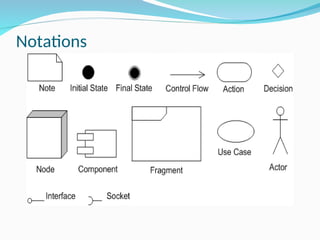
- 25. Notations
- 27. Types of UML Diagrams UML includes the following nine diagrams Class diagram Object diagram Use case diagram Sequence diagram Collaboration diagram Activity diagram Statechart diagram Deployment diagram Component diagram
- 28. Structural Diagrams They represent the static aspect of the system. These static aspects represent those parts of a diagram which forms the main structure and therefore stable The four structural diagrams are: Class diagram Object diagram Component diagram Deployment diagram
- 29. Behavioral diagrams Any system can have two aspects, static and dynamic. A model is considered as complete when both the aspects are covered fully. It basically capture the dynamic aspect of a system. Dynamic aspect can be further described as the changing/moving parts of a system. UML has the following five types of behavioral diagrams: Use case diagram Sequence diagram Collaboration diagram Statechart diagram Activity diagram
- 30. Classes Each class is represented by a rectangle subdivided into three compartments Name Attributes Operations Modifiers are used to indicate visibility of attributes and operations. ‘+’ is used to denote Public visibility (everyone) ‘#’ is used to denote Protected visibility (friends and derived) ‘-’ is used to denote Private visibility (no one) By default, attributes are hidden and operations are visible.
- 31. An example of Class Account_Name - Customer_Name - Balance +addFunds( ) +withDraw( ) +transfer( ) Name Attributes Operations
- 32. OO Relationships There are two kinds of Relationships Generalization (parent-child relationship) Association (student enrolls in course) Associations can be further classified as Aggregation Composition
- 33. Subtype2 Supertype Subtype1 OO Relationships: Generalization - Generalization expresses a parent/child relationship among related classes. - Used for abstracting details in several layers Regular Customer Loyalty Customer Customer Example: Regular Customer Loyalty Customer Customer or:
- 34. OO Relationships: Association Represent relationship between instances of classes Student enrolls in a course Courses have students Courses have exams Etc. Association has two ends Role names (e.g. enrolls) Multiplicity (e.g. One course can have many students) Navigability (unidirectional, bidirectional)
- 35. Association: Multiplicity and Roles University Person 1 0..1 * * Multiplicity Symbol Meaning 1 One and only one 0..1 Zero or one M..N From M to N (natural language) * From zero to any positive integer 0..* From zero to any positive integer 1..* From one to any positive teacher employer Role Role “A given university groups many people; some act as students, others as teachers. A given student belongs to a single university; a given teacher may or may not be working for the university at a particular time.” student
- 36. Association: Model to Implementation Class Student { Course enrolls[4]; } Class Course { Student have[]; } Student Course enrolls has * 4
- 37. OO Relationships: Composition Class W Class P1 Class P2 Composition: expresses a relationship among instances of related classes. It is a specific kind of Whole-Part relationship. It expresses a relationship where an instance of the Whole-class has the responsibility to create and initialize instances of each Part-class. It may also be used to express a relationship where instances of the Part-classes have privileged access or visibility to certain attributes and/or behaviors defined by the Whole-class. Composition should also be used to express relationship where instances of the Whole-class have exclusive access to and control of instances of the Part-classes. Composition should be used to express a relationship where the behavior of Part instances is undefined without being related to an instance of the Whole. And, conversely, the behavior of the Whole is ill-defined or incomplete if one or more of the Part instances are undefined. Whole Class Part Classes Automobile Engine Transmission Example [From Dr.David A. Workman]
- 38. OO Relationships: Aggregation Class C Class E1 Class E2 AGGREGATION Aggregation: expresses a relationship among instances of related classes. It is a specific kind of Container- Containee relationship. It expresses a relationship where an instance of the Container-class has the responsibility to hold and maintain instances of each Containee-class that have been created outside the auspices of the Container-class. Aggregation should be used to express a more informal relationship than composition expresses. That is, it is an appropriate relationship where the Container and its Containees can be manipulated independently. Aggregation is appropriate when Container and Containees have no special access privileges to each other. Container Class Containee Classes Bag Apples Milk Example [From Dr.David A. Workman]
- 39. Aggregation vs. Composition Composition Composition is really a strong form of aggregation •components have only one owner •components cannot exist independent of their owner •components live or die with their owner e.g. Each car has an engine that can not be shared with other cars. •Aggregations may form "part of" the aggregate, but may not be essential to it. They may also exist independent of the aggregate. e.g. Apples may exist independent of the bag.
Editor's Notes
- #2: Evolution of analysis and design techniques Transition from structured programming to object oriented programming
- #3: . What does UML stand for? . Industry standard . Graphical notation . Modeling tool … simplifies software design process
- #4: . More precise than natural language … less detailed than source code . Not dependent on any language . Standardized by various groups
- #5: History: - Rumbaugh – OMT – object modeling technique Jacobson – OOSE UML … unified approach since 1995 UML 1.5 current … UML 2.0 by the end of 2004