SlideShare a Scribd company logo
Schematic Design
PART-1
Introduction
In electronic design automation, until the 1980s schematics were virtually
the only formal representation for circuits. More recently, with the progress
of computer technology, other representations were introduced and
specialized computer languages were developed, since with the explosive
growth of the complexity of electronic circuits, traditional schematics are
becoming less practical.
Schematics for electronic circuits are prepared by designers using EDA
(Electronic Design Automation) tools called schematic capture tools or
schematic entry tools. These tools go beyond simple drawing of devices
and connections. Usually they are integrated into the whole IC design flow
and linked to other EDA tools for verification and simulation of the circuit
under design.
OrCAD Capture
OrCAD Capture
OrCAD capture is a part of the OrCAD family of products
OrCAD is a Suite of tools from
Cadence for design and Layout of
Printed Circuit Boards
OrCAD Capture
OVERVIEW
Creating Part
Library
New/Open
Project
Placing Parts
Signal Connectivity
Establishing
Connectivity between
schematic pages
Editing Design
Assigning
Properties
Generating BoM
and other Reports
Designing for other
EDA Applications and
Saving the project.
Creating Part Library
 Create a New Library (A Library is collection of parts)---
File-> New->Libraries
 Create a New PART----
Right Click on the library->Add New part
Name the part and don’t change anything else
 Draw the part outline using the Place Rectangle Tool
 ADD pins using the Place Pins or Place pin Array tool
 No Duplicate Pins
New/Open – Project
 Creating New Project(Collection of Designs and its Lib)--
File->New->Project
 Enter the NAME of the Project and select the LOCATION of the
project to Save.
 In that Project , Design and Schematic
folder will be created and inside folder
schematic page (Page1) will be created.
 We can rename the page and properties
by right click on that page
 Opening New Project—
File ->Open->Project
New/Open –Project….
 Using Preferences :-
Options->Preferences
It can be used to specify colors,
Grid display, Pan Zoom and so on.
 Using Design template:-
Options->Design Template
It can be used to specify default fonts,
page size , title block, grid references
and so on.
Placing Parts
 We can use tool palette symbol for searching parts or
Place->Parts (p) from tool bar.
 We can ADD  REMOVE Libraries
for addingRemoving the Extra parts.
 To search parts enter the part correctly
and verify with Datasheets
 Click OK , An image of the part is attached to the pointer
 Move the part image and click the left mouse button to place
the part and Press ESC or another tool to dismiss the part
Connectivity
To place a wire :-
 From the Place menu, choose Wire.
 Click the left mouse button to start the wire.
 Use the mouse to draw the wire. Click the left mouse button to
place a vertex and change directions. The vertex is constrained
to multiples of 90 degrees.
 If the wire ends at a pin or another wire, click the left mouse
button to end the wire. The wire appears in the selection color or
 If the wire doesn't connect to anything, double-click to end the
wire.
 Select the selection tool to dismiss the wire tool.
Connectivity…
To place power or ground symbols :-
 From the Place menu, choose Power or Ground. The Place Power
Symbol or Place Ground Symbol dialog box appears.
 In the Place Power dialog box, select a power symbol and click OK
 or In the Place Ground dialog box, select a ground symbol and
click OK.
 Use the mouse to move the symbol to the appropriate location and
click the left mouse button. The symbol appears in the selection
color.
 Select the selection tool , or press ESC, to dismiss the power or
ground tool.
Connectivity b/w Schematic Pages
To extend a net across schematic pages within a single
schematic folder:-
 Open the schematic page editor on a page that contains the net.
 From the Place menu, choose the Off-Page Connector command.
 Select a symbol and enter a name in the Name text box; then click
OK.
 Connect the off-page connector to the net, either by name or by
wire.
 For each schematic page on which the net resides (and within the
same schematic folder), repeat the steps , using the same name
for each off-page connector you place.
Editing Design
To replace a part throughout a design:-
 From the design cache, select the part you want to replace.
 From the Design menu, choose Replace Cache.
 In the dialog box that appears, enter the name of the
replacement part and the library that contains it.
 Select the Replace schematic part properties action if you want
to completely replace the part and its properties. Otherwise, use
the default action to preserve schematic part properties.
 Click OK. When the project manager appears again, double-click
on the design cache to verify that the replacement part is listed
instead of the original part
Editing Design…
We can use the standard Windows drag-and-drop operation to move
or copy schematic folders, schematic pages, libraries, and symbols
between projects, in the project manager windows. If you wish to
copy rather than move, press and hold the CTRL key while you drag
the entity.
 If you are moving or copying a folder or page, verify that:
• for a folder, no Capture editor is open on any document in the
schematic folder.
• for a page, that it is not open in any Capture editor.
 Open both projects in their respective project managers.
 Select the schematic folder, page, library, or symbol that you want to
move or copy, then drag (pressing the CTRL key to copy) the
selection to the destination project manager entity.
 For both projects, from the File menu, choose Save All
Assigning properties
To add a property to a part:-
 Double-click on the part. The property editor appears.
 Click the New button. The Add New Property dialog box appears.
 Enter a name and value for the new property and click OK. You may
enter any name you want, except that property names cannot be
duplicated on a single object.
 Click Apply, and close the property editor.
To edit properties associated with comment text:-
 Select the text you want to edit.
 From the Edit menu, choose Properties. The Display Properties dialog
box appears.
 Make the changes you want to the text, or its font, rotation, color, and
visibility, then click OK
Assigning properties…
To edit the properties of multiple pins:-
 In the part editor, hold the Ctrl key while you click to select each pin.
 From the Edit menu, choose Properties. The Browse spreadsheet
appears.
 Change the properties.
 Click OK to close the Browse spreadsheet.
To edit properties associated with a net, wire, or bus:-
 In the schematic page editor, select the net, wire, or bus.
 From the Edit menu, choose Properties. The property editor
appears.
 Change the properties.
 Click Apply, and close the property editor.
Assigning properties….
To edit an object's properties:-
 Double-click on the object.
 Change the properties in the dialog box or spreadsheet editor
that appears, then click OK or Apply
To delete a property:-
 Double-click on the object. The property editor appears.
 Select the property and click the Delete Property button. Only
user-defined properties can be removed.
 Click Apply, and close the property editor.
Assigning properties……
To remove part references:-
In the project manager, select schematic folders or schematic pages if you
want to process only a portion of the design. If you want to process the
entire design, leave the schematic folders or schematic pages unselected.
From the Tools menu, choose Annotate. The Annotate dialog box appears.
In the Action group box, select Reset part references to "?," select other
options as appropriate, then click OK
Incremental references:-
In the project manager, select schematic folders or schematic pages if you
want to process only a portion of the design. If you want to process the
entire design, leave the schematic folders or schematic pages unselected.
From the Tools menu, choose Annotate. The Annotate dialog box appears.
In the Action group box, select Incremental references update, select other
options as appropriate, then click OK
Generating BoM & Reports
To Generate Standard BoM:-
Report->CIS BoM->Standard
 Whatever we need in the
Output Format We can Add/remove
by selecting them from the properties
To Generate BoM:-
In the project Manager select the design
Tools->Bill Of Materials
from Dialogue box select other options
as appropriate and generate the BoM output.
Generating BoM & Reports..
The Design Rules Check tool scans schematic folders to verify that a
design conforms to design rules; it generates a report of error and
warning messages and places markers on the schematic page to help
you locate problems.
 Select Design from project manager
Tools->Design Rule Check
 From the Dialogue Box select the
Appropriate Boxes and Verify the O/P.
 To delete DRC Markers Select the Action
“Delete Existing DRC Markers” from
Dialogue box and click OK.
Generating BoM & Reports…
To create a Netlist:-
 In the project manager, select the design file for which you
want to create a net list.
Tools->Create Netlist
 Select Layout tab for the netlist.
 Click OK to close and create the
netlist.
Designing for other EDA`s
Designing For ORCAD LAYOUT:-
In the Create Netlist dialog box, choose the Layout tab.
If the board is presently open in Layout, select the Run ECO to Layout
option.
In the Netlist File text box, enter a name for the output file using a .MNL file
extension.
Click OK to close the Create Netlist dialog box and create the .MNL file.
In the Layout session frame's File menu, choose New.
In the Load Template File dialog box, select a technology file (.TCH), then
click OK.
In the Load Netlist File dialog box, select the netlist file with the .MNL file
extension that you created previously, then click OK.
In the Save MAX Board dialog box, select a name for a new output file with
a .MAX file extension, then click OK.
Designing for other EDA`s
Designing For ALLEGRO PCB EDITOR:-
In the Create Netlist dialog box, choose the PCB EDITOR.
If the board is presently open in PCB Editor, select the {Netrev}
option.
Check Create PCB Editor Netlist and Select the Directory to View
output Netlist(.pst, .chp, .prt file extension).
Click OK to close the Create Netlist dialog box.
In the PCB Editor Select File menu, choose Import->Logic.
Browse the Netlist file Location and click ok.
After completion of importing it will show a dialog box “successfully
completed” or “ Completed with Warnings/Errors”.
Edit the capture and follow all the steps up to successfully imported.
Saving and Archive Project
To save a project file along with the design file :-
 In the project manager, select the design file.
 From the File menu, choose Save As.
 Change the drive and directory as appropriate, select the file
name, then click Save.
 In the project manager, select the Design Resources folder.
 From the File menu, choose Save As.
 Change the drive and directory as appropriate, select the file
name, then click Save
Saving and Archive Project
To archive a project:-
Make sure that the project you want to archive is active and the
schematic pages for the project are not open.
From the File menu, choose Archive Project. The Archive Project
dialog box appears.
Select the files you want to be archived with your project. If you do not
select any of the options (Library files, Output files, or Referenced
projects), Capture by default archives only your project (.OPJ) and
design (.DSN) files.
Find and select the directory in which you want your project archived
and click OK. If necessary, create the directory.
REFERENCE :OrCAD CAPTURE USERS GUIDE
The END
??

More Related Content

What's hot (20)

PDF
Electronic Devices and Circuits Manual
Shashank Thawkar
 
PPT
Semiconductor memory
Then Murugeshwari
 
PPTX
SHORT CHANNEL EFFECTS IN MOSFETS- VLSI DESIGN
NITHIN KALLE PALLY
 
PDF
Transistor basics
AtheenaPandian Enterprises
 
PPT
VLSI routing
Naveen Kumar
 
PPTX
Registers
Sanjeev Patel
 
PPT
BASIC ELECTRONICS
Clifford Sugermen
 
PPTX
Diode
Seti Saiman
 
PPTX
Printed board circuit design (Pcb) PPT
HoneyKumar34
 
PPTX
Microprocessor 8085 complete
Shubham Singh
 
PDF
SRAM Design
Bharat Biyani
 
PPT
PCB DESIGN - Introduction to PCB Design Manufacturing
Vibrant Technologies & Computers
 
PDF
VLSI-Physical Design- Tool Terminalogy
Murali Rai
 
PDF
Pcb layout
panchal_jay
 
PPT
Floor planning ppt
Thrinadh Komatipalli
 
PPTX
Integrated circuits
dhawal mehta
 
PPT
Design challenges in physical design
Deiptii Das
 
PPTX
PCB Designing
Anant Prakashrakash Verma
 
PPT
PAL And PLA ROM
RONAK SUTARIYA
 
PPTX
Stick Diagram
Kalyan Acharjya
 
Electronic Devices and Circuits Manual
Shashank Thawkar
 
Semiconductor memory
Then Murugeshwari
 
SHORT CHANNEL EFFECTS IN MOSFETS- VLSI DESIGN
NITHIN KALLE PALLY
 
Transistor basics
AtheenaPandian Enterprises
 
VLSI routing
Naveen Kumar
 
Registers
Sanjeev Patel
 
BASIC ELECTRONICS
Clifford Sugermen
 
Printed board circuit design (Pcb) PPT
HoneyKumar34
 
Microprocessor 8085 complete
Shubham Singh
 
SRAM Design
Bharat Biyani
 
PCB DESIGN - Introduction to PCB Design Manufacturing
Vibrant Technologies & Computers
 
VLSI-Physical Design- Tool Terminalogy
Murali Rai
 
Pcb layout
panchal_jay
 
Floor planning ppt
Thrinadh Komatipalli
 
Integrated circuits
dhawal mehta
 
Design challenges in physical design
Deiptii Das
 
PAL And PLA ROM
RONAK SUTARIYA
 
Stick Diagram
Kalyan Acharjya
 

Similar to Orcad Capture - Schematic Design Tutorial (20)

PDF
Electrónica y PCB: Tutorial de Easyeda V6.4.3
SANTIAGO PABLO ALBERTO
 
DOCX
Solid Modeling Assignment EGR 201-100 Spring 2018 .docx
whitneyleman54422
 
PDF
Easyeda tutorial
SANTIAGO PABLO ALBERTO
 
PDF
DesignSpark PCB Workshop Notes 2018
DesignSparkGC
 
DOCX
PCB Artist Desinging Software Report
Er. Ashish Pandey
 
PDF
08 - Annotating Designs_2022R3-01-01.pdf
LengendaryPhubr
 
DOCX
Auto cad plant-3d
tareaspp27
 
PPTX
Civil project .ppt
PremArumalla
 
PDF
PCB designing in PADS layout
Akash Jadhav
 
DOCX
Practical work 6
wkhairil80
 
PPTX
Computer Aided Design Introduction Lecture
ShavinGopee2
 
PDF
CIC_Manual.pdf
RMani7
 
PPTX
Understanding basic features
Mr_Burns
 
PPT
PCB Design - Printed Circuit Board - VLSI Designing
E2MATRIX
 
PPTX
Chem draw software
Anamikasingh405
 
PPTX
Infotechnogen Solid works
Jagmeet Singh
 
PDF
AUTOCAD Report
AMIT RAJ
 
PDF
SOLIDworks Report File
NEERAJ KUMAR
 
Electrónica y PCB: Tutorial de Easyeda V6.4.3
SANTIAGO PABLO ALBERTO
 
Solid Modeling Assignment EGR 201-100 Spring 2018 .docx
whitneyleman54422
 
Easyeda tutorial
SANTIAGO PABLO ALBERTO
 
DesignSpark PCB Workshop Notes 2018
DesignSparkGC
 
PCB Artist Desinging Software Report
Er. Ashish Pandey
 
08 - Annotating Designs_2022R3-01-01.pdf
LengendaryPhubr
 
Auto cad plant-3d
tareaspp27
 
Civil project .ppt
PremArumalla
 
PCB designing in PADS layout
Akash Jadhav
 
Practical work 6
wkhairil80
 
Computer Aided Design Introduction Lecture
ShavinGopee2
 
CIC_Manual.pdf
RMani7
 
Understanding basic features
Mr_Burns
 
PCB Design - Printed Circuit Board - VLSI Designing
E2MATRIX
 
Chem draw software
Anamikasingh405
 
Infotechnogen Solid works
Jagmeet Singh
 
AUTOCAD Report
AMIT RAJ
 
SOLIDworks Report File
NEERAJ KUMAR
 
Ad

More from Pantech ProLabs India Pvt Ltd (20)

PDF
Registration process
Pantech ProLabs India Pvt Ltd
 
PPTX
Choosing the right processor for embedded system design
Pantech ProLabs India Pvt Ltd
 
PPT
Brain Computer Interface
Pantech ProLabs India Pvt Ltd
 
PPTX
Electric Vehicle Design using Matlab
Pantech ProLabs India Pvt Ltd
 
PPTX
Image processing application
Pantech ProLabs India Pvt Ltd
 
PPTX
Internet of Things using Raspberry Pi
Pantech ProLabs India Pvt Ltd
 
PPTX
Internet of Things Using Arduino
Pantech ProLabs India Pvt Ltd
 
PPTX
Brain controlled robot
Pantech ProLabs India Pvt Ltd
 
PPTX
Brain Computer Interface-Webinar
Pantech ProLabs India Pvt Ltd
 
PPTX
Development of Deep Learning Architecture
Pantech ProLabs India Pvt Ltd
 
PPTX
Gate driver design and inductance fabrication
Pantech ProLabs India Pvt Ltd
 
PPTX
Brainsense -Brain computer Interface
Pantech ProLabs India Pvt Ltd
 
PPT
Median filter Implementation using TMS320C6745
Pantech ProLabs India Pvt Ltd
 
PPT
Introduction to Code Composer Studio 4
Pantech ProLabs India Pvt Ltd
 
PPT
Waveform Generation Using TMS320C6745 DSP
Pantech ProLabs India Pvt Ltd
 
PPT
Interfacing UART with tms320C6745
Pantech ProLabs India Pvt Ltd
 
PPT
Switch & LED using TMS320C6745 DSP
Pantech ProLabs India Pvt Ltd
 
PPT
Led blinking using TMS320C6745
Pantech ProLabs India Pvt Ltd
 
PPT
Introduction to tms320c6745 dsp
Pantech ProLabs India Pvt Ltd
 
Registration process
Pantech ProLabs India Pvt Ltd
 
Choosing the right processor for embedded system design
Pantech ProLabs India Pvt Ltd
 
Brain Computer Interface
Pantech ProLabs India Pvt Ltd
 
Electric Vehicle Design using Matlab
Pantech ProLabs India Pvt Ltd
 
Image processing application
Pantech ProLabs India Pvt Ltd
 
Internet of Things using Raspberry Pi
Pantech ProLabs India Pvt Ltd
 
Internet of Things Using Arduino
Pantech ProLabs India Pvt Ltd
 
Brain controlled robot
Pantech ProLabs India Pvt Ltd
 
Brain Computer Interface-Webinar
Pantech ProLabs India Pvt Ltd
 
Development of Deep Learning Architecture
Pantech ProLabs India Pvt Ltd
 
Gate driver design and inductance fabrication
Pantech ProLabs India Pvt Ltd
 
Brainsense -Brain computer Interface
Pantech ProLabs India Pvt Ltd
 
Median filter Implementation using TMS320C6745
Pantech ProLabs India Pvt Ltd
 
Introduction to Code Composer Studio 4
Pantech ProLabs India Pvt Ltd
 
Waveform Generation Using TMS320C6745 DSP
Pantech ProLabs India Pvt Ltd
 
Interfacing UART with tms320C6745
Pantech ProLabs India Pvt Ltd
 
Switch & LED using TMS320C6745 DSP
Pantech ProLabs India Pvt Ltd
 
Led blinking using TMS320C6745
Pantech ProLabs India Pvt Ltd
 
Introduction to tms320c6745 dsp
Pantech ProLabs India Pvt Ltd
 
Ad

Recently uploaded (20)

PDF
CEREBRAL PALSY: NURSING MANAGEMENT .pdf
PRADEEP ABOTHU
 
PPTX
How to Create a PDF Report in Odoo 18 - Odoo Slides
Celine George
 
PDF
CONCURSO DE POESIA “POETUFAS – PASSOS SUAVES PELO VERSO.pdf
Colégio Santa Teresinha
 
PDF
Knee Extensor Mechanism Injuries - Orthopedic Radiologic Imaging
Sean M. Fox
 
PPTX
Universal immunization Programme (UIP).pptx
Vishal Chanalia
 
PDF
Chapter-V-DED-Entrepreneurship: Institutions Facilitating Entrepreneurship
Dayanand Huded
 
PPTX
grade 5 lesson matatag ENGLISH 5_Q1_PPT_WEEK4.pptx
SireQuinn
 
PPTX
PATIENT ASSIGNMENTS AND NURSING CARE RESPONSIBILITIES.pptx
PRADEEP ABOTHU
 
PDF
Dimensions of Societal Planning in Commonism
StefanMz
 
PDF
ARAL-Orientation_Morning-Session_Day-11.pdf
JoelVilloso1
 
PDF
Women's Health: Essential Tips for Every Stage.pdf
Iftikhar Ahmed
 
PDF
LAW OF CONTRACT (5 YEAR LLB & UNITARY LLB )- MODULE - 1.& 2 - LEARN THROUGH P...
APARNA T SHAIL KUMAR
 
PPTX
2025 Winter SWAYAM NPTEL & A Student.pptx
Utsav Yagnik
 
PPTX
Stereochemistry-Optical Isomerism in organic compoundsptx
Tarannum Nadaf-Mansuri
 
PDF
The History of Phone Numbers in Stoke Newington by Billy Thomas
History of Stoke Newington
 
PDF
BÀI TẬP BỔ TRỢ TIẾNG ANH 8 - GLOBAL SUCCESS - CẢ NĂM - NĂM 2024 (VOCABULARY, ...
Nguyen Thanh Tu Collection
 
PDF
DIGESTION OF CARBOHYDRATES,PROTEINS,LIPIDS
raviralanaresh2
 
PDF
The dynastic history of the Chahmana.pdf
PrachiSontakke5
 
PDF
0725.WHITEPAPER-UNIQUEWAYSOFPROTOTYPINGANDUXNOW.pdf
Thomas GIRARD, MA, CDP
 
PDF
The Constitution Review Committee (CRC) has released an updated schedule for ...
nservice241
 
CEREBRAL PALSY: NURSING MANAGEMENT .pdf
PRADEEP ABOTHU
 
How to Create a PDF Report in Odoo 18 - Odoo Slides
Celine George
 
CONCURSO DE POESIA “POETUFAS – PASSOS SUAVES PELO VERSO.pdf
Colégio Santa Teresinha
 
Knee Extensor Mechanism Injuries - Orthopedic Radiologic Imaging
Sean M. Fox
 
Universal immunization Programme (UIP).pptx
Vishal Chanalia
 
Chapter-V-DED-Entrepreneurship: Institutions Facilitating Entrepreneurship
Dayanand Huded
 
grade 5 lesson matatag ENGLISH 5_Q1_PPT_WEEK4.pptx
SireQuinn
 
PATIENT ASSIGNMENTS AND NURSING CARE RESPONSIBILITIES.pptx
PRADEEP ABOTHU
 
Dimensions of Societal Planning in Commonism
StefanMz
 
ARAL-Orientation_Morning-Session_Day-11.pdf
JoelVilloso1
 
Women's Health: Essential Tips for Every Stage.pdf
Iftikhar Ahmed
 
LAW OF CONTRACT (5 YEAR LLB & UNITARY LLB )- MODULE - 1.& 2 - LEARN THROUGH P...
APARNA T SHAIL KUMAR
 
2025 Winter SWAYAM NPTEL & A Student.pptx
Utsav Yagnik
 
Stereochemistry-Optical Isomerism in organic compoundsptx
Tarannum Nadaf-Mansuri
 
The History of Phone Numbers in Stoke Newington by Billy Thomas
History of Stoke Newington
 
BÀI TẬP BỔ TRỢ TIẾNG ANH 8 - GLOBAL SUCCESS - CẢ NĂM - NĂM 2024 (VOCABULARY, ...
Nguyen Thanh Tu Collection
 
DIGESTION OF CARBOHYDRATES,PROTEINS,LIPIDS
raviralanaresh2
 
The dynastic history of the Chahmana.pdf
PrachiSontakke5
 
0725.WHITEPAPER-UNIQUEWAYSOFPROTOTYPINGANDUXNOW.pdf
Thomas GIRARD, MA, CDP
 
The Constitution Review Committee (CRC) has released an updated schedule for ...
nservice241
 

Orcad Capture - Schematic Design Tutorial

  • 2. Introduction In electronic design automation, until the 1980s schematics were virtually the only formal representation for circuits. More recently, with the progress of computer technology, other representations were introduced and specialized computer languages were developed, since with the explosive growth of the complexity of electronic circuits, traditional schematics are becoming less practical. Schematics for electronic circuits are prepared by designers using EDA (Electronic Design Automation) tools called schematic capture tools or schematic entry tools. These tools go beyond simple drawing of devices and connections. Usually they are integrated into the whole IC design flow and linked to other EDA tools for verification and simulation of the circuit under design.
  • 4. OrCAD Capture OrCAD capture is a part of the OrCAD family of products OrCAD is a Suite of tools from Cadence for design and Layout of Printed Circuit Boards
  • 5. OrCAD Capture OVERVIEW Creating Part Library New/Open Project Placing Parts Signal Connectivity Establishing Connectivity between schematic pages Editing Design Assigning Properties Generating BoM and other Reports Designing for other EDA Applications and Saving the project.
  • 6. Creating Part Library  Create a New Library (A Library is collection of parts)--- File-> New->Libraries  Create a New PART---- Right Click on the library->Add New part Name the part and don’t change anything else  Draw the part outline using the Place Rectangle Tool  ADD pins using the Place Pins or Place pin Array tool  No Duplicate Pins
  • 7. New/Open – Project  Creating New Project(Collection of Designs and its Lib)-- File->New->Project  Enter the NAME of the Project and select the LOCATION of the project to Save.  In that Project , Design and Schematic folder will be created and inside folder schematic page (Page1) will be created.  We can rename the page and properties by right click on that page  Opening New Project— File ->Open->Project
  • 8. New/Open –Project….  Using Preferences :- Options->Preferences It can be used to specify colors, Grid display, Pan Zoom and so on.  Using Design template:- Options->Design Template It can be used to specify default fonts, page size , title block, grid references and so on.
  • 9. Placing Parts  We can use tool palette symbol for searching parts or Place->Parts (p) from tool bar.  We can ADD REMOVE Libraries for addingRemoving the Extra parts.  To search parts enter the part correctly and verify with Datasheets  Click OK , An image of the part is attached to the pointer  Move the part image and click the left mouse button to place the part and Press ESC or another tool to dismiss the part
  • 10. Connectivity To place a wire :-  From the Place menu, choose Wire.  Click the left mouse button to start the wire.  Use the mouse to draw the wire. Click the left mouse button to place a vertex and change directions. The vertex is constrained to multiples of 90 degrees.  If the wire ends at a pin or another wire, click the left mouse button to end the wire. The wire appears in the selection color or  If the wire doesn't connect to anything, double-click to end the wire.  Select the selection tool to dismiss the wire tool.
  • 11. Connectivity… To place power or ground symbols :-  From the Place menu, choose Power or Ground. The Place Power Symbol or Place Ground Symbol dialog box appears.  In the Place Power dialog box, select a power symbol and click OK  or In the Place Ground dialog box, select a ground symbol and click OK.  Use the mouse to move the symbol to the appropriate location and click the left mouse button. The symbol appears in the selection color.  Select the selection tool , or press ESC, to dismiss the power or ground tool.
  • 12. Connectivity b/w Schematic Pages To extend a net across schematic pages within a single schematic folder:-  Open the schematic page editor on a page that contains the net.  From the Place menu, choose the Off-Page Connector command.  Select a symbol and enter a name in the Name text box; then click OK.  Connect the off-page connector to the net, either by name or by wire.  For each schematic page on which the net resides (and within the same schematic folder), repeat the steps , using the same name for each off-page connector you place.
  • 13. Editing Design To replace a part throughout a design:-  From the design cache, select the part you want to replace.  From the Design menu, choose Replace Cache.  In the dialog box that appears, enter the name of the replacement part and the library that contains it.  Select the Replace schematic part properties action if you want to completely replace the part and its properties. Otherwise, use the default action to preserve schematic part properties.  Click OK. When the project manager appears again, double-click on the design cache to verify that the replacement part is listed instead of the original part
  • 14. Editing Design… We can use the standard Windows drag-and-drop operation to move or copy schematic folders, schematic pages, libraries, and symbols between projects, in the project manager windows. If you wish to copy rather than move, press and hold the CTRL key while you drag the entity.  If you are moving or copying a folder or page, verify that: • for a folder, no Capture editor is open on any document in the schematic folder. • for a page, that it is not open in any Capture editor.  Open both projects in their respective project managers.  Select the schematic folder, page, library, or symbol that you want to move or copy, then drag (pressing the CTRL key to copy) the selection to the destination project manager entity.  For both projects, from the File menu, choose Save All
  • 15. Assigning properties To add a property to a part:-  Double-click on the part. The property editor appears.  Click the New button. The Add New Property dialog box appears.  Enter a name and value for the new property and click OK. You may enter any name you want, except that property names cannot be duplicated on a single object.  Click Apply, and close the property editor. To edit properties associated with comment text:-  Select the text you want to edit.  From the Edit menu, choose Properties. The Display Properties dialog box appears.  Make the changes you want to the text, or its font, rotation, color, and visibility, then click OK
  • 16. Assigning properties… To edit the properties of multiple pins:-  In the part editor, hold the Ctrl key while you click to select each pin.  From the Edit menu, choose Properties. The Browse spreadsheet appears.  Change the properties.  Click OK to close the Browse spreadsheet. To edit properties associated with a net, wire, or bus:-  In the schematic page editor, select the net, wire, or bus.  From the Edit menu, choose Properties. The property editor appears.  Change the properties.  Click Apply, and close the property editor.
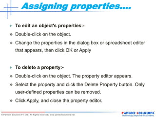
  • 17. Assigning properties…. To edit an object's properties:-  Double-click on the object.  Change the properties in the dialog box or spreadsheet editor that appears, then click OK or Apply To delete a property:-  Double-click on the object. The property editor appears.  Select the property and click the Delete Property button. Only user-defined properties can be removed.  Click Apply, and close the property editor.
  • 18. Assigning properties…… To remove part references:- In the project manager, select schematic folders or schematic pages if you want to process only a portion of the design. If you want to process the entire design, leave the schematic folders or schematic pages unselected. From the Tools menu, choose Annotate. The Annotate dialog box appears. In the Action group box, select Reset part references to "?," select other options as appropriate, then click OK Incremental references:- In the project manager, select schematic folders or schematic pages if you want to process only a portion of the design. If you want to process the entire design, leave the schematic folders or schematic pages unselected. From the Tools menu, choose Annotate. The Annotate dialog box appears. In the Action group box, select Incremental references update, select other options as appropriate, then click OK
  • 19. Generating BoM & Reports To Generate Standard BoM:- Report->CIS BoM->Standard  Whatever we need in the Output Format We can Add/remove by selecting them from the properties To Generate BoM:- In the project Manager select the design Tools->Bill Of Materials from Dialogue box select other options as appropriate and generate the BoM output.
  • 20. Generating BoM & Reports.. The Design Rules Check tool scans schematic folders to verify that a design conforms to design rules; it generates a report of error and warning messages and places markers on the schematic page to help you locate problems.  Select Design from project manager Tools->Design Rule Check  From the Dialogue Box select the Appropriate Boxes and Verify the O/P.  To delete DRC Markers Select the Action “Delete Existing DRC Markers” from Dialogue box and click OK.
  • 21. Generating BoM & Reports… To create a Netlist:-  In the project manager, select the design file for which you want to create a net list. Tools->Create Netlist  Select Layout tab for the netlist.  Click OK to close and create the netlist.
  • 22. Designing for other EDA`s Designing For ORCAD LAYOUT:- In the Create Netlist dialog box, choose the Layout tab. If the board is presently open in Layout, select the Run ECO to Layout option. In the Netlist File text box, enter a name for the output file using a .MNL file extension. Click OK to close the Create Netlist dialog box and create the .MNL file. In the Layout session frame's File menu, choose New. In the Load Template File dialog box, select a technology file (.TCH), then click OK. In the Load Netlist File dialog box, select the netlist file with the .MNL file extension that you created previously, then click OK. In the Save MAX Board dialog box, select a name for a new output file with a .MAX file extension, then click OK.
  • 23. Designing for other EDA`s Designing For ALLEGRO PCB EDITOR:- In the Create Netlist dialog box, choose the PCB EDITOR. If the board is presently open in PCB Editor, select the {Netrev} option. Check Create PCB Editor Netlist and Select the Directory to View output Netlist(.pst, .chp, .prt file extension). Click OK to close the Create Netlist dialog box. In the PCB Editor Select File menu, choose Import->Logic. Browse the Netlist file Location and click ok. After completion of importing it will show a dialog box “successfully completed” or “ Completed with Warnings/Errors”. Edit the capture and follow all the steps up to successfully imported.
  • 24. Saving and Archive Project To save a project file along with the design file :-  In the project manager, select the design file.  From the File menu, choose Save As.  Change the drive and directory as appropriate, select the file name, then click Save.  In the project manager, select the Design Resources folder.  From the File menu, choose Save As.  Change the drive and directory as appropriate, select the file name, then click Save
  • 25. Saving and Archive Project To archive a project:- Make sure that the project you want to archive is active and the schematic pages for the project are not open. From the File menu, choose Archive Project. The Archive Project dialog box appears. Select the files you want to be archived with your project. If you do not select any of the options (Library files, Output files, or Referenced projects), Capture by default archives only your project (.OPJ) and design (.DSN) files. Find and select the directory in which you want your project archived and click OK. If necessary, create the directory.
  • 26. REFERENCE :OrCAD CAPTURE USERS GUIDE The END ??