


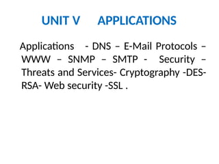


![• Data Transmission occurs between sender and
receiver over some Transmission Medium
or Transmission Media.
• Transmission Media may be classified into Two
Types :
i) Guided Media [Wired Technology]
ii) Unguided Media [Wireless Technology]](https://image.slidesharecdn.com/pptdcn-241217052954-a1fa5625/85/ppt_dcn-pptx-networks-networks-security-of-networks-30-320.jpg)


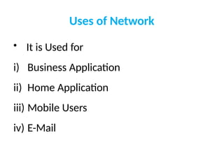
![Bluetooth
layers
Radio Layer: Roughly equivalent to physical layer of the Internet
model.
Physical links can be synchronous or asynchronous.
◦ Uses Frequency-hopping spread spectrum [Changing frequency of usage].
Changes it modulation frequency 1600 times per second.
◦ Uses frequency shift keying (FSK )with Gaussian bandwidth filtering
to transform bits to a signal.
Baseband layer: Roughly equivalent to MAC sublayer in LANs.
Access is using Time Division (Time slots).
◦ Length of time slot = dwell time = 625 microsec. So, during one
frequency
, a sender sends a frame to a slave, or a slave sends a frame to
the master.
Time division duplexing TDMA (TDD-TDMA) is a kind of half-duplex
communication in which the slave and receiver send and receive data,
but not at the same time (half-duplex). However
, the communication
for each direction uses different hops, like walkie-talkies.](https://image.slidesharecdn.com/pptdcn-241217052954-a1fa5625/85/ppt_dcn-pptx-networks-networks-security-of-networks-241-320.jpg)

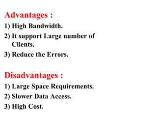
![Physical
Links
Synchronous connection-oriented (SCO)
◦ Latency is important than integrity.
◦ Transmission using slots.
◦ No retransmission.
Asynchronous connectionless link (ACL)
◦ Integrity is important than latency.
◦ Does like multiple-slave communication.
◦ Retransmission is done.
L2CAP (Logical Link Control and Adaptation Protocol)
◦ Equivalent to LLC sublayer in LANs.
◦ Used for data exchange on ACL Link. SCO channels do not use L2CAP
.
◦ Frame format has 16-bit length [Size of data coming from upper layer in
bytes],
channel ID, data and control.
◦ Can do Multiplexing, segmentation and Reassembly, QoS [with no QoS, best-
effort delivery is provided] and Group mangement [Can do like multicast
group, using some kind of logical addresses].](https://image.slidesharecdn.com/pptdcn-241217052954-a1fa5625/85/ppt_dcn-pptx-networks-networks-security-of-networks-243-320.jpg)


ppt_dcn.pptx networks networks security of networks
- 1. 19CAB09 – DATA COMMUNICATION AND NETWORKS Prepared by S.NITHYANANTH, ASP DEPARTMENT OF MCA MUTHAYAMMAL ENGINEERING COLLEGE,RASIPURAM.
- 2. OBJECTIVES • To understand and basic • To understand components communication. and data required for • To analyze the function and • To Acquire knowledge of various developed for internet.
- 3. UNIT I NETWORK FUNDAMENTALS Introduction to Networks – Categories of Networks -Communication model –Data transmission concepts and terminology – Protocol architecture – Protocols – OSI – TCP/IP – LAN Topology - Transmission media.
- 4. UNIT II DATA LINK LAYER Data link control – Error Detection – VRC – LRC – CRC – Checksum – Error Correction – Hamming Codes – MAC – Ethernet, Token ring , Token Bus – Wireless LAN - Bluetooth – Bridges.
- 5. UNIT III NETWORK LAYER Network layer – Switching concepts – Circuit switching – Packet switching – IP Addressing –IPV4, IPV6 – Routing Protocols – Distance Vector – Link State.
- 6. UNIT IV TRANSPORT LAYER Transport layer – service – Connection establishment – Flow control – Transmission control protocol – Congestion control and avoidance – User datagram protocol - Transport for Real Time Applications (RTP).
- 7. UNIT V APPLICATIONS Applications - DNS – E-Mail Protocols – WWW – SNMP – SMTP - Security – Threats and Services- Cryptography -DES- RSA- Web security -SSL .
- 8. OUTCOMES • Able to trace the flow of information from one node to another node in the network. • Able to Identify the components required to build different types of networks. • Able to understand the functionalities needed for data communication into layers. • Able to choose the required functionality at each layer for given application. • Able to understand the working principles of various application protocols. • Acquire knowledge about security issues and services available.
- 9. REFERENCES 1.Forouzan, “ Data Communication and Networking”, Fifth Edition , TMH 2012 2. Larry L. Peterson & Bruce S. Davie, “Computer Networks – A systems Approach”, Fourth Edition, Harcourt Asia / Morgan Kaufmann, 2010. 3.William Stallings, “Data and Computer Communications”, Nineth Edition, Prentice Hall 2011. David J. Edition , Wetherall, Pearson 4. Andrew S.Tannenbaum “Computer Networks”Fifth Education 2011 5.James F. Kurose, Keith W. Ross, “Computer Networking: A Top-down Approach, Pearson Education, Limited, sixth edition,2012. 6. John Cowley, “Communications and Networking : An Introduction”, Springer Indian Reprint, 2010.
- 10. UNIT – I NETWORK FUNDAMENTALS
- 11. OVERVIEW • Introduction to Networks • Categories of Networks • Communication Model • Data Transmission Concepts and Terminology • Protocol Architecture • Protocols • OSI • TCP/IP • LAN Topology • Transmission Media
- 12. Introduction to Networks • A Network: A group of devices that can communicate with each other over links. • Each device is called a host. Each host has a unique address.
- 13. • Network is a connection between two or more devices. • Which is connected by a communication links. • A node can be computer, printer or any other devices which is capable of sending and receiving information at each other.
- 14. Example:
- 15. INTERNET • An internet: each host has an address of the form n/h where n is the network number and h is the number of the host on network n.
- 16. Uses of Network • It is Used for i) Business Application ii) Home Application iii) Mobile Users iv) E-Mail
- 17. Categories or Types of Network • There are Three Types: 1. LAN - Local Area Network 2. MAN - Metropolitan Area Network 3. WAN – Wide Area Network
- 18. 1. LAN - Local Area Network A LAN is Designed by Local Area Connections such as: i) within Building ii) within office iii) within Campus iv) within Specific Place
- 19. Advantages : 1) Sharing of Files. 2) Sharing of Programs. 3) Communication Exchange. Disadvantages : 1) Reliability. 2) Capacity. 3) High Cost.
- 20. 2. MAN - Metropolitan Area Network A Metropolitan Area Network (MAN) is a network that interconnects users with computer resources in a geographic area or region larger than that covered by even a large local area network (LAN) but smaller than the area covered by a wide area network (WAN).
- 21. • MAN supports up to 150 Kilometers Distance. • Example: Telephone Network Cable TV
- 22. Advantages : 1) High Bandwidth. 2) It support Large number of Clients. 3) Reduce the Errors. Disadvantages : 1) Large Space Requirements. 2) Slower Data Access. 3) High Cost.
- 23. 3. WAN – Wide Area Network • WAN Provide a Long Distance Transmission of Data. • By Using WAN Exchange the Information from one country to another country.
- 24. Components of Network - Which gives the Request. - Which gives the Response. - It Indicates Modulator / Demodulator. - Which identifies the Path between Client & Server. - Which overcomes the Traffic problems.
- 25. Communication Model • Data communications are exchange of data between two devices via some transmission medium. • It should be done in two ways i) Local - It takes LAN Connection. ii)Remote - It takes Long distance like MAN & WAN. • Data should be Transferred in the form of 0’s and 1’s
- 26. 1) Delivery - The System must deliver the data to the correct Destination. 2) Accuracy - The System must deliver the data at Accurate way. Source Transmission Medium Destination
- 27. 3)Timeline - The System must deliver the data at Exact Time. 4) Jitter - It refers to the variable in the i) Sender ii) Receiver iii) Medium iv) Message v) Protocol
- 28. 1. Sender 2. Receiver 3. Medium 5. Protocol Step : 1 Step : 2 4. Message 5. Protocol Step : 1 Step : 2
- 29. : It is a device , that Sends the information to the Receiver. : It is a device , that Receives the information from the Sender. : It is the physical path between Sender to Receiver. : This is the passing Informations. : It is a set of rules and regulations that “ Governed “ from data communication.
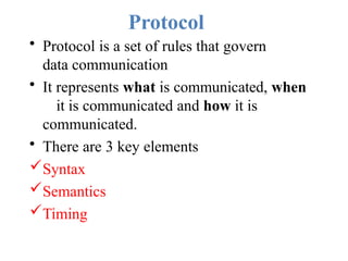
- 30. • Data Transmission occurs between sender and receiver over some Transmission Medium or Transmission Media. • Transmission Media may be classified into Two Types : i) Guided Media [Wired Technology] ii) Unguided Media [Wireless Technology]
- 31. i) Guided Media (Wired Network) • In Guided Media Signals are Passed in a “ same physical path” • Example: i) Twisted pair Cable ii) Coaxial Cable iii) Fiber Optic Cable
- 32. ii) Unguided Media (Wireless Network) • In Unguided Media Signals are Passed in the form of “ Electromagnetic Waves” • Example : i) Mobile phones ii) Satellite microwave iii) Infrared
- 33. It Provides a dedicated links between two devices. • For example, a wired system that connects two computers together can be thought of a point- to-point link.
- 34. It is a link between two or more devices. It is also known as Multi- Point configuration. The networks having multipoint configuration are called
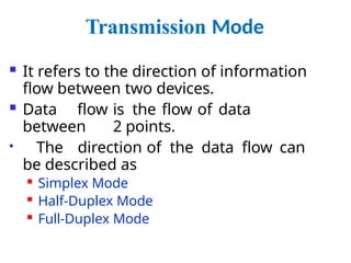
- 35. Transmission Mode It refers to the direction of information flow between two devices. Data flow is the flow of data between 2 points. The direction of the data flow can be described as Simplex Mode Half-Duplex Mode Full-Duplex Mode
- 36. Simplex: Data flows in only one direction on the data communication line (medium). Examples are Radio and Television broadcasts. Half-Duplex: Data flows in both directions but only one direction at a time on the data communication line. Ex. Conversation on walkie-talkies. Full-Duplex: Data flows in both directions simultaneously. Modems are configured to flow data in both directions. Ex. Phone Conversation
- 37. Figure 1.2 Data flow (simplex, half-duplex, and full- Data Flow
- 38. Protocol Architecture • It is a layered structure of H/W and S/W that supports exchange of data b/w systems • It supports distributed applications(E- Mail, File Transfer) • Each layer of protocol architecture provides some set of rules • There are 2 widely used protocol architecture TCP/IP Architecture OSI Model
- 39. Protocol • Protocol is a set of rules that govern data communication • It represents what is communicated, when it is communicated and how it is communicated. • There are 3 key elements Syntax Semantics Timing
- 40. Syntax • It represents structure, Format of data the order in which it is presented Data may contain: • First 8 bit -> Sender Address • Second 8 bit -> Receiver Address • Remaining bits-> message stream
- 41. SEMANTICS • It refers the meaning of each section of bit TIMING • It refers when data sent and how fast it is sent (Says Characteristics) • Ex:100Mbps
- 42. • It provides model for the development of product regardless of individual manufacturer • It falls in 2 categories
- 44. De Facto standard • Not officially adopted but used widespread • It has 2 categories • Proprietary->Wholly owned by company • Non-Proprietary->Group or communiy developed for public
- 45. De Jure Standard • A Standard Legislated by an officially recognized body Standard Organizations: • International Standard Organization • ANSI • IEEE
- 46. The OSI Model • An ISO (International standard Organization) that covers all aspects of network communications is the Open System Interconnection (OSI) model. • An open system is a model that allows any two different systems to communicate regardless of their underlying architecture (hardware or software). • The OSI model is not a protocol; it is model for understanding and designing a network architecture that is flexible, robust and interoperable.
- 47. • The OSI model is a layered framework for the design of network systems that allows for communication across all types of computer systems. • The OSI model is built of seven ordered layers: 1. (Layer 1) Physical layer 2. (Layer 2) Data link layer 3. (Layer 3) Network layer 4. (Layer 4) Transport layer 5. (Layer 5) Session layer 6. (Layer 6) Presentation layer 7. (Layer 7) Application layer
- 49. Peer-to-Peer Process • Within a single machine, each layer calls upon services of the layer just below it. • Layer 3, for example, uses the services provided by layer 2 and provides services for layer 4. • Between machines, layer x on one machine communicates with layer x on another machine, by using a protocol (this is Peer-to-Peer Process). • Communication between machines is therefore a peer-to- peer process using protocols appropriate to a given layer.
- 50. Interfaces between Layers • There is an interface between each pair of adjacentlayers. This interface defines what provide information and services a layer must for the layer above it.
- 51. Functions of Layers 1. Physical Layer The physical layer is responsible for transmitting individual bits from one node to the next.
- 52. Physical layer The physical layer is concerned with the following: • Physical characteristics of interfaces and media: It define the type of transmission media • Representation of the bits: the physical layer data consist of a stream of bits(0,1). The transmitted bits must be encoded into signals – electrical or optical. The physical layer defines the type of encoding. • Data rate: The physical layer defines the transmission rate, the number of bits sent each second.
- 53. Physical Layer • Line configuration: the physical layer is concerned with the connection of devices to the medium. • Physical topology – Ring, star • Transmission Mode - Simplex, Half duplex Full Duplex
- 54. 2. Data Link Layer • It is responsible for node-to-node delivery of data.
- 55. Functions of the Data Link Layer: • Framing. The data link layer divides the stream of bits received from the network layer into data units called frames. • Physical addressing. If frames are to be distributed to different systems on the network, the data link layer adds a header to the frame to define the physical address of the sender (source address) and/or receiver (destination address) of the frame. • If the frame is intended for a system outside the sender’s network, the receiver address is the address of the device that connects one network to the next.
- 57. • Flow Control. If the rate at which the data are absorbed by the receiver is less than the rate produced in the sender, the data link layer imposes a flow control mechanism to prevent overwhelming the receiver. • Error control. The data link layer adds reliability to the physical layer by adding mechanisms to retransmit damaged or lost frames. Error detect and control is normally achieved through a trailer to the end of the frame. • Access Control. When two or more devices are connected to the same link, data link layer protocols are necessary to determine which device has control over the link at any time.
- 58. 3. Network Layer • The Network layer is responsible for the source- to- destination delivery of a packet possible across multiple networks. •It converts Frames into packets. •If two systems are connected to the same link, there is usually no need for a network layer. However, if the two systems are attached to different networks, there is often a need for the network layer to accomplish source-to-destination delivery.
- 59. Network Layer Functions: •Logical addressing-Physical addressing (May change) handle addressing problem locally •If packet pass the network boundary, we need another addressing called logical addressing (Never change) •Routing - Route the packet to final destination The network layer is responsible for the delivery of packets from the original source to the final destination.
- 60. 4. Transport Layer • The transport layer is responsible for process-to-process or end-end delivery of the entire message. • The network layer oversees host-to-destination delivery of individual packets, it does not recognize any relationship between those packets. • The transport layer ensures that the whole message arrives intact and in order, overseeing both error control and flow control at the process-to-process level.
- 61. Transport layer The transport layer is responsible for delivery of a message from one process to another.
- 62. Functions of the Transport layer Service point addressing: Computer often run several processes (running programs) at the same time. Process-to-process delivery means delivery from a specific process on one computer to a specific process on the other. • The transport layer header include a type of address called port address. • The network layer gets each packet to the correct computer; the transport layer gets the entire message to the correct process on that computer.
- 63. Cont.. , • Segmentation and reassembly: a message is divided into transmittable segments, each having a sequence number. These numbers enable the transport layer to reassemble the message correctly upon arrival at the destination. • Connection control: The transport layer can be either connectionless or connection-oriented. • A connectionless transport layer treats each segment as an independent packet and delivers it to the transport layer at the destination machine. • A connection-oriented transport layer makes a connection with the transport layer at the destination machine first before delivering the packets. After all the data are transferred, the connection is terminated.
- 64. Functions of the transport layer • Flow control: the transport layer performs a flow control end to end. The data link layer performs flow control across a single link. • Error control: the transport layer performs error control end to end. The data link layer performs control across a single link. • Congestion control concerns controlling traffic entry into a telecommunication networks so as to avoid congestive collapse by attempting to avoid oversubscription of any of the processing or link capabilities of the intermediate nodes and networks and taking resource reducing steps, such as reducing the rate of sending packets. It should not be confused with flow control, which prevents the sender from overwhelming the receiver.
- 65. 5. Session Layer • The session layer is responsible for dialog control and synchronization.
- 66. Functions of Session Layer • Decision Control:- Half duplex, Full Duplex • Synchronization: Adding checkpoints to stream data. • Ex: System sending 2000 pages. • Add check point after each 100th page. • So in case of failure no need to sent whole page.
- 67. 6. Presentation Layer • It is concerned with the syntax and semantics of the information exchanged b/w 2 devices.
- 68. Functions of Presentation Layer • Translation: Interoperability b/w different encoding formats. • Encryption: Converting plain to cipher text and vice versa. • Compression: Reducing number of bits in multimedia data when transmitting.
- 69. 7. Application layer The application layer is responsible for providing services to the user.
- 70. Functions of Application Layer • It provides user access to network. • X.500-Directory service. • X.400-Message handling service. • FTAM- File Transfer management. • Network Virtual Terminal. Access and
- 71. • Transmission Control Protocol / Internetworking Protocol is used in the internet and is developed prior to the OSI model. • It would not match exactly with OSI model • It is divided into layers.
- 72. TCP/IP protocol
- 73. • It contains relatively independent protocols that can mixed and matched with depend on needs of the system.
- 74. • It defines the Physical (or) Logical arrangement of Links in a Network. • Topology refers to the layout of connected devices in a network. • The Topology of the Network is Geometric Representation of the relationship between all Communication links.
- 75. Types of Topology i) Mesh Topology ii) Star Topology iii) Tree Topology iv) Bus Topology v) Ring Topology vi) Hybrid Topology
- 76. Types of Topology • Here every device has a direct point to point link between every other device. • A fully connected mesh can have n(n- 1)/2 physical channels to link n devices. if n=5 (Number of Nodes) 5(5-1)/2 = 10 ( Communication Links) • 5 Nodes are Connected by using 10 Communication Links
- 77. Mesh Topology
- 78. Mesh Topology Advantages: • It eliminate the traffic problem. • It is robustness. • It has privacy and security. • Fault can be easily found.
- 79. Mesh Topology Disadvantages: • More number of cables to be used. • Every devices must be connected to some other devices. So installation process is very difficult.
- 80. Types of Topology • Each device has a dedicated point-to-point link between only a central controller or “HUB”. • The devices are not directly linked to some other devices. • If one device wants to send data to another device, it sends to the central controller and the Central controller send to other device.
- 81. Star Topology Star Topology Diagram: Central controller (or) HUB D A C B
- 82. Star Topology Advantages : • Less expensive than Mess topology. • Less number of cables to be used. • It is robustness.
- 83. Star Topology Disadvantages: • Each device must connected to controller. • It require more installation process. • If central controller failure means devices should be failed. central all the
- 84. Types of Topology • Tree topology has some variation from star topology. • The nodes in the tree are linked to the central controller. • The primary HUB in the tree is represented by “Active Hub”. • The secondary HUB in the tree is represented by “Passive Hub”.
- 85. Tree Topology
- 86. Tree Topology Advantages: • It allows more devices to be attached in a single central controller. • It allows the network to prioritize the communication.
- 87. Tree Topology Disadvantages: • Each device must be linked to controller. • It require more installation processes. • If central controller failure means system should fail down. central entire
- 88. Types of Topology • A Bustopology describes the multipoint configuration. • One long cable act as a backbone to link all the devices in a network. • Devices are connected in a bus topology with the help of “Drop lines” and “Tapes”.
- 89. Bus Topology Bus Topology Diagram: Back bone bone Drop line Drop line Tape Back A D C B
- 90. Bus Topology Advantages: • Installation process is very easy. • Redundancy can be eliminated. • Less number of cables to be used.
- 91. Bus Topology Disadvantages: • Reconfiguration is very difficult. • Very difficult to adding (or) deleting of a devices
- 92. Types of Topology • InRing Topology each device has dedicated point-to-point link between other devices. • The signals are passed along the “ring” in only one direction from device to device. • Each devices in a ring should have a “Repeater”.
- 93. Ring Topology Ring Topology Diagram: Ring A C D B
- 94. Advantages: • Easy to install and reconfigure. • Fault can be easily identified. Ring Topology
- 95. Ring Topology Disadvantages: • It is unidirectional traffic. • In rings if one device gets failure then the entire system should be failed.
- 96. VI. Hybrid Topology Combination of all topology is called hybrid topology.
- 98. The physical path between transmitter and receiver. • Repeaters or amplifiers may be used to extend the length of the medium. • Communication of electromagnetic waves is guided or unguided.
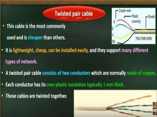
- 102. Twisted-pair cable
- 103. UTP and STP
- 109. Coaxial Cable
- 110. BNC connectors •To connect coaxial cable to devices, it is necessary to use coaxial connectors. The most common type of connector is the Bayone-Neill- Concelman, or BNC, connectors. Applications include cable TV networks, and some traditional Ethernet LANs like 10Base-2, or 10-Base5.
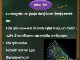
- 113. Optical fibers
- 114. Propagation Modes (Types of Optical Fiber )
- 115. Propagation Modes
- 132. THANK YOU
- 133. UNIT II DATA LINK LAYER Data link control – Error Detection – VRC – LRC – CRC – Checksum – Error Correction – Hamming Codes – MAC – Ethernet, Token ring , Token Bus – Wireless LAN - Bluetooth – Bridges.
- 134. UNIT – II DATA LINK LAYER
- 135. OVERVIEW • Data Link Control • Error Detection • VRC • LRC • CRC • Checksum • Error Correction • Hamming Codes • MAC • Ethernet • Token ring • Token Bus • Wireless LAN • Bluetooth • Bridges
- 136. Data Link Control Communication Minimum 2 devices are needed for data communication. So line discipline is necessary for co-operation b/w 2 devices. The 2 important functions of data link layer is flow control and error control.This functions are otherwise called as Data link control.
- 137. Line Discipline It coordinates the link system It is done in 2 ways ◦ ENQ (Enquiry) Used in peer – peer communication Enquire whether there is a required link b/w two devices Check whether the intended device is capable to receive ◦ ACK (Acknowledgment) Used in Primary secondary communication The intended device will acknowledge about its status to the receiver
- 138. There are 2 categories in line discipline
- 140. Select It is a line discipline used in topologies with primary secondary relationship. Select It is uses whenever the primary device has something to send.ie)Primary controls the link.
- 141. Select
- 142. Selec t
- 143. Pol l The polling function is used by the primary device to Select transmissions from the secondary devices. If the primary device is ready to receive data , It ask each device in turn if it has anything to send.
- 144. Pol l
- 145. Flow Control It is a set of procedures to tell the sender how much data it can transmit before it must wait for an acknowledgement from the receiver. Two categories of flow control: ◦ Stop-and-wait Send one frame at a time. ◦ Sliding window Send several frames at a time.
- 147. Stop-and- wait Sender sends one frame and waits for an acknowledgement before sending the next frame.
- 148. Stop-and-wait Advantages: ◦ Simplicity. ◦ Each frame is checked and acknowledged before the next frame is sent. Disadvantages: ◦ Slow. Can add significantly to the total transmission time if the distance between devices is long. ◦ Inefficiency Each frame is alone on the line.
- 149. SlidingWindow Sender can send several frames before needing an acknowledgement. Advantages: ◦ The link can carry several frames at once. ◦ Its capacity can be used efficiently.
- 150. Error Control
- 152. Error Detection
- 153. Error Detection
- 154. Can detect all single-bit errors. Can detect burst errors only if the total Even number of ones –add 0 Odd number of ones – add 1
- 155. •Increases the likelihood of detecting burst errors. •n bits LRC can detect a burst error of n bits. •Errors may be undetected if: •Have even number of errors in that position.
- 158. You will experience a painful sharpening from time to time, but this is required if you are to become a better pencil.
- 159. Error Correction
- 160. Redundancy Bits
- 161. You have the ability to correct any mistakes you might make.
- 162. Hamming Codes-Error correction Hamming codes, like polynomial codes, are appended to the transmitted message Hamming codes, unlike polynomial codes, contain the information necessary to locate a single bit error
- 163. Calculating the Hamming Code The key to the Hamming Code is the use of extra parity bits to allow the identification of a single error. Create the code word as follows: ◦ Mark all bit positions that are powers of two as parity bits. (positions 1, 2, 4, 8, 16, 32, 64,etc.) ◦ All other bit positions are for the data to be encoded. (positions 3, 5, 6, 7, 9, 10, 11, 12, 13, 14, 15, 17, etc.) ◦ Each parity bit calculates the parity for some of the bits in the code word.The position of the parity bit determines the sequence of bits that it alternately checks and skips. Position 1: check 1 bit, skip 1 bit, check 1 bit, skip 1 bit, etc. (1,3,5,7,9,11,13,15,...) Position 2: check 2 bits, skip 2 bits, check 2 bits, skip 2 bits,etc. (2,3,6,7,10,11,14,15,...) Position 4: check 4 bits, skip 4 bits, check 4 bits, skip 4 bits,etc. (4,5,6,7,12,13,14,15,20,21,22,23,...) Position 8: check 8 bits, skip 8 bits, check 8 bits, skip 8bits, etc. (8-15,24- 31,40- 47,...) Position 16: check 16 bits,skip 16 bits,check 16 bits, skip 16 bits, etc.(16- 31,48- 63,80-95,...) Position 32: check 32 bits,skip 32 bits,check 32 bits, skip 32 bits,etc.(32- 63,96-
- 164. Position of Redundancy bit in Hamming code
- 165. Error
- 166. Error Control
- 167. Stop-and-Wait A R Q
- 168. Sliding window ARQ
- 172. MAC IEEE has subdivided(Project 802) the data link layer into two sub layers: ◦ Logical Link Control ◦ Medium access control Functions of MAC It resolves the contention of shared media It contains all information to move information from one place to another It contains the physical address of next station to route packet. MAC protocol are specific to LAN
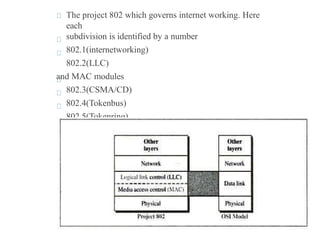
- 173. The project 802 which governs internet working. Here each subdivision is identified by a number 802.1(internetworking) 802.2(LLC) and MAC modules 802.3(CSMA/CD) 802.4(Tokenbus) 802.5(Tokenring)
- 174. Figure 13.1 IEEE standard for LANs
- 175. MAC protocol are specific to LANLAN is a Local Area Network used for communication inside building Protocols for LAN are, ◦ Ethernet ◦ Token Ring ◦ Token bus ◦ FDDI
- 176. IEEE STANDARDS Ethernet: It is a LAN protocol that is used in Bus and Star topologiesand implements CSMA/CD as the medium access method Original (traditional) Ethernet developed in 1980 by three companies: Digital, Intel, Xerox (DIX). In 1985, the Computer Society of the IEEE started a project, called Project 802, to set standards to enable intercommunication among equipment from a variety of manufacturers. Current version is called IEEE Ethernet
- 177. ◦ IEEE 802.3 supports LAN standard Ethernet ◦ IEEE802.3 defines two categories Baseband Broadband ◦ Base band has five different category 10Base5 10Base2 10BaseT 1Base5 etc., ◦ Broad band has a category
- 178. Access Method:CSMA/CD When multiple user access the single line ,there is a danger of signals overlapping and destroying each other(Traffic) .such an overlap is called Collisions. T o avoid this the access method used in Ethernet is carrier sense multiple access/collision detection In CSMA any workstation wishing to transmit must listen to existing traffic on the line If no voltage is detected ,line is considered idle CSMA cuts down the number of collisions, but cant eliminate. Collisions still occur if both station try to listen at a time.
- 179. Figure 13.4 802.3 MAC frame
- 180. IEEE Ethernet In IEEE 802.3 Ethernet Data link layer is split into two sublayers: ◦ Bottom part: MAC The frame is called IEEE 802.3 Handles framing, MAC addressing, MediumAccess control Specific implementation for each LAN protocol Defines CSMA/CD as the access method for Ethernet LANs and Token passing method for Token Ring. Implemented in hardware ◦ Top part: LLC (Logical Link Control) The subframe is called IEEE 802.2 Provides error and flow control if needed It makes the MAC sublayer transparent Allows interconnectivity between different LANs data link layers Used to multiplex multiple network layer protocols in the data link laye r frame Implemented in
- 181. Ethernet Provides Unreliable, connectionless Service ◦ Ethernet data link layer protocol provides connectionless service to the network layer No handshaking between sending and receiving adapter. ◦ Ethernet protocol provides Unreliable service to the network layer : Receiving adapter doesn’t send ACK or NAK to sending adapter This means stream of datagrams passed to network layer can have gaps (missing data) Gaps will be filled if application is using reliable transport layer protocol Otherwise, application will see the gaps
- 182. Ethernet FCS Frame formats. (a) DIX Ethernet ,(b) IEEE 802.3. FCS Ethernet Frame format
- 183. Ethernet Frame PREAMBLE ◦ 8 bytes with pattern 10101010 used to synchronize receiver, sender clock rates. ◦ In IEEE 802.3, eighth byte is start of frame (10101011) Addresses: 6 bytes (explained latter) Type (DIX) ◦ Indicates the type of the Network layer protocol being carried in the payload (data) field, mostly IP but others may be supported such as IP (0800), Novell IPX (8137) and AppleTalk (809B), ARP (0806) ) ◦ Allow multiple network layer protocols to be supported on a single machine (multiplexing) ◦ Its value starts at 0600h (=1536 in decimal) Length (IEEE 802.3): number of bytes in the data field. ◦ Maximum 1500 bytes (= 05DCh) CRC: checked at receiver, if error is detected, the frame is discarded ◦ CRC-32 Data: carries data encapsulated from the upper-layer protocols Pad: Zeros are added to the data field to make the minimum data length = 46 bytes
- 184. Ethernet address Six bytes = 48 bits Flat address not hierarchical Burned into the NIC ROM First three bytes from left specify the vendor. Cisco 00- 00- 0C, 3Com 02-60-8C and the last 24 bit should be created uniquely by the company Destination Address can be: Unicast: second digit from left is even (one recipient) Multicast: Second digit from left is odd (group of stations to receive the frame – conferencing applications) Broadcast (ALL ones) (all stations receive the frame) Source address is always Unicast
- 185. Figure 13.3 Ethernet evolution through four generations
- 186. Categories of traditional Ethernet •<data rate><Signaling method><Max segment length or cable type>
- 187. IEEE 802.3 Cable Types Name Cable Max. Max Cable Segment Length Nodes /segment Toplogy 10Base5 thick coax 500 meters 100 Bus 10Base2 thin coax 185 meters 30 Bus 10BaseT twisted pair 100 meters 1 Star 10BaseF Fiber Optic 2Km 1 Star
- 188. Figure 13.10 10Base5 implementation
- 189. Connection of stations to the medium using 10Base2
- 190. 10BaseT • Uses twisted pair Cat3 cable Star-wire topology • A hub functions as a repeater with additional functions • Fewer cable problems, easier to troubleshoot than coax • Cable length at most 100 meters
- 191. Figure 13.12 10Base-T implementation
- 192. Figure 13.13 10Base-F implementation
- 193. Fast Ethernet 100 Mbps transmission rate same frame format, media access, and collision detection rules as 10 Mbps Ethernet can combine 10 Mbps Ethernet and Fast Ethernet on same network using a switch media: twisted pair (CAT 5) or fiber optic cable (no coax) Star-wire topology ◦ Similar to 10BASE-T CAT 3 CAT 5
- 194. Figure 13.19 Fast Ethernet topology
- 195. Figure 13.20 Fast Ethernet implementations
- 196. Gigabit Ethernet Speed 1Gpbs Minimum frame length is 512 bytes Operates in fu l/half duplex modes mostly full duplex
- 197. In the full-duplex mode of Gigabit Ethernet, there is no collision; the maximum length of the cable is determined by the signal attenuation in the cable.
- 198. Figure 13.23 Gigabit Ethernet implementations
- 199. 10Gbps Ethernet Maximum link distances cover 300 m to 40 km Full-duplex mode only No CSMA/CD Uses optical fiber only
- 200. Token Ring It allows each station to sent one frame . The access control mechanism used by Ethernet is inefficient sometimes because of collision. It solves the collision problem by passing token Initially a station waits for token, if a token is free the station may send a data frame
- 201. Cont.. , This frame proceeds around the ring ,being regenerated by each station .Each station examines the destination address finds the frame is addressed to another station and relays it to its neighbor. The intended recipient recognizes its own address and copies the message and set the address bit The token finally reach the sender and it recognizes that the data is delivered through address bit Token is passed from NIC to NIC
- 202. Token Ring
- 203. Token Bus It combines the feature of token ring and Ethernet
- 204. FDDI • Fiber Distributed Data Interface • local area network protocol standardized by ANSI • 100-Mbps token passing • Dual-ring LAN • A high-speed backbone technology • High bandwidth • Optical fiber transmission • Allows up to 1000 stations
- 205. FDDI Architecture
- 206. Components of FDDI • Fiber optic cable • A concentrator (ring) • Stations: 2 types • DAS (Dual Attachment Station) or Class A: • Connected to both the rings • SAS (Single Attachment Station) or Class B: • Connected to primary ring
- 207. FDDI Frame Format Similar to token ring frame
- 208. Networking and internetworking devices: An internet is a interconnection of individual network. So to create a internet we need a internetworking devices. ie) Linking a number of LAN’s Internet - WWW internet-Interconnection of LAN
- 209. Why Interconnect? • To separate / connect one corporate division with another. • To connect two LANs with differentprotocols. • To connect a LAN to the Internet. • To break a LAN into segments to relieve traffic congestion. • To provide a security wall between two different types ofusers.
- 211. Introductio n •Many times it is necessary to connect a local area network to another local area network or to a wide area network. •Local area network to local area network connections are usually performed with a bridge. •Local area network to wide area network connections are usually performed with a router. •A third device, the switch, can be used to interconnect segments of a local area network.
- 213. Repeater: A repeater is a regenerator, not an amplifier A repeater installed on a link receives the signal before it becomes too weak or corrupted ,regenerates the original bit pattern, and put the refreshed copy back onto the link.
- 214. Gateways: A gateway is a protocol convertor. It accepts a packet format for one protocol(e.g., Apple Talk) and convertsit into a packet format for another protocol(e.g.,TCP/IP).
- 215. 104 / 25 A gateway SNA network (IBM) Netware network (Novell)
- 216. 105 / 25 Bridge s Divide a large network into smaller segment It filters the traffic . It contains logic(Bridge table) that allows them to keep the traffic for each segment separate. Ie) Isolating and controlling the link problems (e.g.congestion) Bridges have look-up table that contains physical address of every station connected to it.
- 218. 108 / 25 Bridge
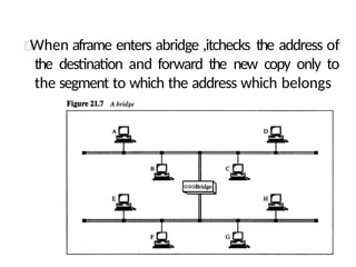
- 219. When aframe enters abridge ,itchecks the address of the destination and forward the new copy only to the segment to which the address which belongs
- 221. Simple Bridge It is a less expensive type of bridge It links 2 segments (LANS) and lists the address of all the stations in table included in each of them. Here address must be entered manually. The table is modified when stations are added and removed.
- 222. Multiport Bridge It is used to connect more than two LANS. So the bridge has 3 tables. Here address must be entered manually Transparent Bridge: • A transparent or learning bridge builds its table of station on its own (automatically). • The table is empty when it is installed, it builds its table when it encounters the packet for transmission. It uses the source address for building table. • It identifies the changes and update the table when system moved from one station to another
- 224. Cont. , Bridges are normally installed redundantly,that is two LANS may be connected by more than one bridge.in this cases they may create a loop. So packet may go round and round,It can be avoided by algorithms like ◦ Spannig tree algorithm ◦ Source routing
- 226. Data Communications and Computer Networks Remote Bridges •A remote bridge is capable of passing a data frame from one local area network to another when the two LANs are separated by a long distance and there is a wide area network connecting the two LANs. •A remote bridge takes the frame before it leaves the first LAN and encapsulates the WAN headers and trailers. •When the packet arrives at the destination remote bridge, that bridge removes the WAN headers and trailers leaving the original frame.
- 227. Data Communications and Computer Networks Switche s •A switch is a combination of a hub and a bridge (multi- port bridge). •It can interconnect two or more workstations, but like a bridge, it observes traffic flow and learns. •When a frame arrives at a switch, the switch examines the destination address and forwards the frame out the one necessary connection. •Workstations that connect to a hub are on a shared segment. •Workstations that connect to a switch are on a switched segment.
- 228. Wireless LANs
- 229. LAN/WLAN World LANs provide connectivity for interconnecting computing resources at the local levels of an organization Wired LANs Limitations because of physical,hard- wired infrastructure Wireless LANs provide Flexibility Portability Mobility Ease of
- 231. IEEE 802.11 Wireless LAN Standard In response to lacking standards, IEEE developed the first internationally recognized wireless LAN standard – IEEE 802.11 IEEE published 802.11 in 1997, after seven years of work Scope of IEEE 802.11 is limited to Physical and Data Link Layers.
- 232. Benefits of 802.11 Standard Appliance Interoperability Fast Product Development Stable Future Migration Price Reductions The 802.11 standard takes into account the following significant differences between wireless and wired LANs: Power Management Security Bandwidth
- 233. WLAN Topology Ad-Hoc Network The BSS without an AP is a stand-alone network and cannot send data to other BSSs. they can locate one another and agree to be part of a BSS.
- 234. WLAN Topology Infrastructure EX: cellular network if we consider each BSS to be a cell and each AP to be a basestation.
- 235. Basic service sets (BSSs)
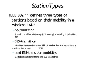
- 236. StationTypes IEEE 802.11 defines three types of stations based on their mobility in a wireless LAN: ◦ no-transition A station is either stationary (not moving) or moving only inside a BSS ◦ BSS-transition station can move from one BSS to another , but the movement is confined inside one ESS. ◦ and ESS-transition mobility. A station can move from one ESS to another
- 237. collision avoidanceCSMAICA network allocation vector (NAV) used to avoid collision. ◦ RTS frame includes the duration of time that it needs to occupy the channel. ◦ stations affected by this transmission create a timer called (NAV) ◦ the network allocation vector (NAV) shows the time must pass before these stations allowed to check the channel for idleness. there is no mechanism for collision detection, if the sender has not received a CTS frame from the receiver, assumes there has been a collision ,the sender tries again.
- 238. BLUETOOTH Bluetooth is a wireless LAN technology designed to connect devices of different functions such as telephones, notebooks, computers, and so on. A cameras, printers, coffee makers, Bluetooth LAN is an ad hoc network, which means that the network is formed spontaneously. Bluetooth defines two types of networks: piconet and scatternet.
- 239. Picone tA Bluetooth network is called a piconet, or a small net. It can have up to eight stations, one of which is called the master; the rest are called slaves. Maximum of seven slaves. Only one master. Slaves synchronize their clocks and hopping sequence with the master. But an additional eight slaves can stay in parked state, which means they can be synchronized with the master but cannot take part in communication until it is moved from the parked state.
- 240. Scatternet Piconets can be combined to form what is called a scatternet. A slave station in one piconet can become the master in • another piconet. Bluetooth devices has a built-in short-range radio transmitter.
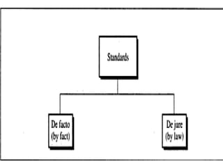
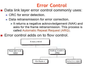
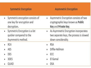
- 241. Bluetooth layers Radio Layer: Roughly equivalent to physical layer of the Internet model. Physical links can be synchronous or asynchronous. ◦ Uses Frequency-hopping spread spectrum [Changing frequency of usage]. Changes it modulation frequency 1600 times per second. ◦ Uses frequency shift keying (FSK )with Gaussian bandwidth filtering to transform bits to a signal. Baseband layer: Roughly equivalent to MAC sublayer in LANs. Access is using Time Division (Time slots). ◦ Length of time slot = dwell time = 625 microsec. So, during one frequency , a sender sends a frame to a slave, or a slave sends a frame to the master. Time division duplexing TDMA (TDD-TDMA) is a kind of half-duplex communication in which the slave and receiver send and receive data, but not at the same time (half-duplex). However , the communication for each direction uses different hops, like walkie-talkies.
- 242. Bluetooth layers
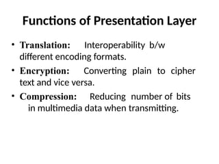
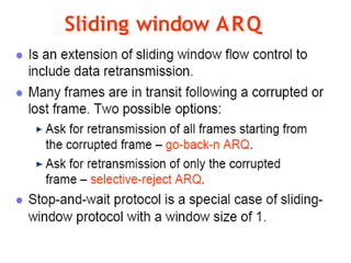
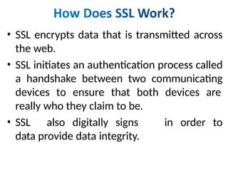
- 243. Physical Links Synchronous connection-oriented (SCO) ◦ Latency is important than integrity. ◦ Transmission using slots. ◦ No retransmission. Asynchronous connectionless link (ACL) ◦ Integrity is important than latency. ◦ Does like multiple-slave communication. ◦ Retransmission is done. L2CAP (Logical Link Control and Adaptation Protocol) ◦ Equivalent to LLC sublayer in LANs. ◦ Used for data exchange on ACL Link. SCO channels do not use L2CAP . ◦ Frame format has 16-bit length [Size of data coming from upper layer in bytes], channel ID, data and control. ◦ Can do Multiplexing, segmentation and Reassembly, QoS [with no QoS, best- effort delivery is provided] and Group mangement [Can do like multicast group, using some kind of logical addresses].
- 244. THANK YOU
- 245. UNIT III NETWORK LAYER Network layer – Switching concepts – Circuit switching – Packet switching – IP Addressing –IPV4, IPV6 – Routing Protocols – Distance Vector – Link State.
- 246. UNIT – III NETWORK LAYER
- 247. • Network Layer OVERVIEW • Switching Concepts • Circuit Switching • Packet Switching • Message Switching • IP Addressing • IPV4 • IPV6 • Routing Protocols • Distance Vector Routing • Link State Routing
- 248. Network Layer •The Network layer is responsible for the source-to-destination delivery of a packet possible across multiple networks. • It converts Frames into packets.
- 249. • Source-to-Destination delivery of a packet • Logical addressing • Routing • Internetworking
- 251. Switching Concepts Switches are hardware or software devices used for temporary connection b/w 2 or more devices linked to the switch in network but not to each another Switches are needed to connect multiple devices for making one-one communication TYPES: • • •
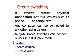
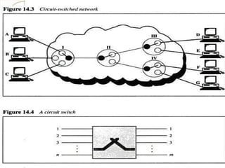
- 253. Circuit switching It creates direct physical connection b/w two devices such as phone or computers. Any computer can be connected to any other using Levers. N-by-N folded switches can connect n lines in full duplex mode. 2 types: ◦ ◦
- 256. Space Division Switch Path in the circuit are separated from each other It is used both in analog and digital communication 2 Types: ◦ Crossbar switch ◦ Multistage switch • Crossbar Switch: It connects n inputs to moutputs using cross points • Limitation:
- 257. Crossbar Switch:
- 258. Multistage switch Devices are linked to switches ,that are in turn linked to another switches(Hierarchy of switches)
- 259. Blocking: The reduction in a number of cross points causes a phenomena called Blocking. During heavy traffic one input cannot be connected to output because no path available
- 260. Time Division Switches It uses time division multiplexing 2 methods: Time slot interchange TDM bus Time slot interchange: It changesthe ordering of the slot based on the desired connection It uses RAM to store time slot Ex: 1->3 2->4 3->1 4- >2
- 261. TSI
- 263. TDM Bus-Time Division Multiplexing Here each input and output lines are connected to high speed bus Each bus is closed during one of the four time slots
- 264. Limitations of Circuit Switching • It is specially designed for voice suitable communication(telephone). Not for data communication. • Once a circuit is established, it remains for duration of the session. It creates dialed(temporary)and leased(Permanent). • Less data rate because of point to connection. poin t
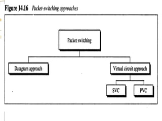
- 265. Packet switching • Packet switching is better for data transmission. • Here data are transmittedthrough unit of variable length blocks called packets. • Longer transmission are divided multiple packets. • Packet length is decided by network. int o
- 267. DatagramApproach • In this approach a message is divided into multiple packets. • All packets choose various routes and reaches the destination. • Ordering of packets in destination is done by transport layer.
- 268. DatagramApproach
- 269. Virtual Circuit approach It uses single route to send all packets of the message Two formats: ◦ Switched virtual circuit ◦ Permanent virtual circuit SVC • Connection is temporary • Dial-up lines DuringTransmission. A connection is established-all packets proper ACK- Connection is terminated are sent –
- 271. PVC • Connection is permanent. • Circuit is dedicated for two users, No one else can use the line when communication takes place. • It always gets the same route. • Leased lines. During Transmission. No connection establishment or termination
- 272. PVC
- 273. Circuit switchedVs Virtual Circuit Path Vs Route: Circuit switched- >Path Virtual Circuit- >route
- 274. Message Switching • It uses a mechanism called store and forward • Here a message is received and stored until a appropriate route is free, then sends along. • Message switching- uses secondary storage(Disk) • Packet switching – uses primary storage(RAM)
- 276. Routers • The routers decide which route is best among many routes in a particular transmission. • Routers are like stations on the network Routing concepts: Least cost routing: Cheaper Shortest path(using small number of relays or hops. Hop-count ->Number of relays
- 277. Non - Adaptive Routing In some routing protocols , once a pathway to a destination is selected ,the router sends all packets in that way. Adaptive Routing: The router may select new route for each packet. Packet Life Time (or)Time to Live: The problem created by looping or bouncing is avoided by destroying the packet without looping, New packet is retransmitted
- 278. • To route the packet with optimal cost many routing algorithms are used to Calculating the shortest path between 2 routers 1. Distance Vector Routing 2. Link State Routing
- 279. Distance vector Routing Def: • Each router periodically shares its knowledge about the entire network with its neighbor. • It is represented by graph. Key Works: • Each router shares its knowledge about the entire network to neighbors. • Routing only to the directly linked routers. • Information sharing at regular interval(each 30 seconds).
- 280. The Concept of Distance Vector Routing
- 281. Distance Vector Routing Table 12/28/202 Unit-3 : Network 2 8 1
- 283. Link State Routing Def: Each router shares its knowledge of it neighborhood with all routers in the internetwork. It is represented by directed graph with weight. Key work: Each router shares its knowledge about the neighborhood Each router sends its knowledge to all router. Flooding -> Each router share info to neighbor, The neighbor to its own neighbor and so on., Information sharing when there is a change.
- 284. Concept of Link State Routing
- 285. Cost in Link State Routing
- 286. Link State Packet 12/28/202 Unit-3 : Network 2 8 6
- 287. Link State Database 12/28/202 Unit-3 : Network 2 8 7
- 288. TCP/ IP calle d • It was developed before OSI • This project was funded by ARPA of U.S ARPANET which is turned into TCP/IP networ k • In internet it acts like a single connection many of any size and type. • TCP and UDP creates a data unit called Segment or datagram.
- 291. What is an IP address? An Internet Protocol address is a numerical label assigned to each device connected to a computer network that uses the Internet Protocol for communication. An IP address serves two principal functions: host or network interface identification location addressing.
- 292. IP (Internet Proocol) Network layer of TCP/IP supports IP in turn four other supporting protocol ◦ ICMP ◦ IGMP ◦ ARP ◦ RARP It is a transmission mechanism used by TCP/IP protocols
- 293. IP datagram
- 294. C ont., IP Is a unreliable and connection less datagram protocol. No error checking or tracking. Data transmitted to destination but no guarantees. IP must be paired with TCP.
- 295. IP Addressing In addition to physical address (NIC) ,to identify each device in the network it requires IP address. Address that identify host of its network. An IP address is a 32-bit address. The IP addresses are unique and universal. It Represented in a Dotted-decimal Notation.
- 296. Example 1 Change the following IP addresses from binary notation to dotted- decimal notation. a. 10000001 00001011 b. 11111001 10011011 00001011 11101111 11111011 00001111 Solution We replace each group of 8 bits with its equivalent decimal number and add dots for separation: a. b. 129.11.11.239 249.155.251.15
- 297. Example 2 Change the following IP addresses from dotted-decimal notation to binary notation. a. b. 111.56.45.78 75.45.34.78 Solution We replace each decimal number with its binary equivalent (see Appendix B): a. 01101111 b. 00111000 00101101 01001110 01001011 00101101 00100010 01001110
- 299. Figure 19.10 Finding the class in binary notation
- 300. Finding the class in decimal notation (changes from 0 to 255)
- 301. Class Starting IPAddress Ending IPAddress # of Hosts A 10.0.0.0 10.255.255.255 16,777,216 B 172.16.0.0 172.31.255.255 1,048,576 C 192.168.0.0 192.168.255.255 65,536 Private and Public IP Address
- 304. Types of IP address Static address Dynamic address Static IP address ◦ manually input by network administrator. ◦ manageable for
- 305. Types of IP address Dynamic IP address examples - BOOTP, DHCP ◦ Assigned by server when host boots ◦ Derived automatically from a range of addresses ◦ Duration of ‘lease’ negotiated, then address released back to server
- 306. Subnetting Dividing the network into several smaller groups (subnets) with each group having its own subnet IP address. Site looks to rest of internet like single network and routers outside the organization route the packet based on the main Network address. Local routers route within subnetted network using subnet address.
- 307. Subnettin g Host portion of address partitioned into subnet number (most significant part) and host number (least significant part) In this case, IP address will have 3 levels (Main network, subnet, host) Subnet mask is a 32-bit consists of zeros and ones that indicates which bits of the IP address are subnet number and which are host number Subnet mask when AND ed with the IP address it gives the subnetwork address
- 308. Masking . Masking is a process that extracts the address of the physical network from an IP address. Boundary level masking: Here the mask numbers are either 255 or 0, finding the subnetwork address is very easy. Non-boundary level masking. If mask numbers are not just 255 or 0, finding the subnetwork address
- 309. Supernetting: • Supernetting combines several networks into one lager one (Because of Address reduction)
- 310. IP Network Addressing INTERNET world’s largest public data network, doubling in size every nine months IPv4, defines a 32-bit address - 232 (4,294,967,296) IPv4 addresses available The first problem is concerned with the eventual depletion of the IP address space. Traditional model of classful addressing does not allow the address space to be used to its maximum potential.
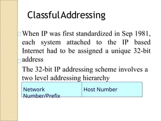
- 311. ClassfulAddressing When IP was first standardized in Sep 1981, each system attached to the IP based Internet had to be assigned a unique 32-bit address The 32-bit IP addressing scheme involves a two level addressing hierarchy Network Number/Prefix Host Number
- 312. Internet Protocol (IP) What is Internet Protocol? ◦ Internet Protocol is a set of technical rules that defines how computers communicate over a network. ◦ Currently, There are two versions of IP IP version 4 (IPv4) IP version 6 (IPv6).
- 313. Internet Protocol (IP) What is IPv4? ◦ IPv4 was the first version of Internet Protocol to be widely used, and accounts for most of today’s Internet traffic. ◦ There are just over 4 billion IPv4 addresses. While that is a lot of IP addresses, it is not enough to last forever.
- 314. Internet Protocol (IP) What is IPv6? ◦ IPv6 is a newer numbering system that provides a much larger address pool than IPv4. It was deployed in 1999 and should meet the world’s IP addressing needs well into the future.
- 315. Internet Protocol (IP) What is the major difference? ◦ The major difference between IPv4 and IPv6 is the number of IP addresses. ◦ There are 4,294,967,296 IPv4 addresses. ◦ while, there are 340,282,366,920,938,463,463,374,607,431 , 768,211,456 IPv6 addresses.
- 316. 128-bit IPv6 Address 3FFE:085B:1F1F:0000:0000:0000:00A9:1234 8 groups of 16-bit hexadecimal numbers separated by “:” Leading zeros can be removed 3FFE:85B:1F1F::A9:1234 :: = all zeros in one or more group of 16-bit hexadecimal numbers
- 317. IPv4 vs. IPv6 IPv6 IPv4 addresses are 32 bit length. IPv6 addressesare 128 bit length. IPv4 addresses are binaryIPv6 addresses are binary numbersrepresented innumbers decimals. represented in hexadecimals. IPSec support is only optional. Inbuilt IPSec support. Fragmentation is done by Fragmentation is done only sender and forwarding by sender.
- 318. No packet flow identification. Packet flow identification is available within the IPv6 header using the Flow Label field. Checksum field is available in IPv4 header No checksum field in IPv6 header. Options fields are available in IPv4 header. No option fields, but IPv6 Extension headers are available. Address Resolution Protocol
- 319. Internet Group Management Protocol (IGMP) is used to manage multicast group membership. IGMP is replaced with Multicast Listener Discovery (MLD) messages. Broadcast messages are available. Broadcast messages are not available. Instead a link- local scope "All nodes" multicast IPv6 address(FF02::1) is used for broadcast similar functionality. Manual configuration (Static) of IPv4 addresses or DHCP (Dynamic Host configuration Protocol) Auto-configuration of addresses is available.
- 320. IPv4 companion protocols (1) ARP: Address Resolution Protocol ◦ Mapping from IP address to MAC address ICMP: Internet Control Message Protocol ◦ Error reporting & Query IGMP: Internet Group Management Protocol ◦ Multicast member join/leave Unicast Routing Protocols (Intra-AS) ◦ Maintaining Unicast Routing Table ◦ E.g. RIP, OSPF (Open Shortest Path
- 321. IPv4 companion protocols (2) Multicast Routing Protocols ◦ Maintaining Multicast Routing Table ◦ E.g. DVMRP, MOSPF, CBT, PIM Exterior Routing Protocols (Inter- AS) ◦ E.g. BGP (Border Gateway Protocol) Quality-of-Service Frameworks ◦ Integrated Service (ISA, IntServ) ◦ Differentiated Service (DiffServ)
- 322. Why IPv6? Deficiency of IPv4 Address space exhaustion New types of service Integration ◦ Multicast ◦ Quality of Service ◦ Security ◦ Mobility (MIPv6) Header and format
- 323. Advantages of IPv6 over IPv4 Larger address space Better header format New options Allowance for extension Support for resource allocation Support for more security Support for mobility
- 324. THANK YOU
- 325. UNIT IV TRANSPORT LAYER Transport layer – service – Connection establishment – Flow control – Transmission control protocol – Congestion control and avoidance – User datagram protocol - Transport for Real Time Applications (RTP).
- 326. UNIT – IV TRANSPORT LAYER
- 327. OVERVIEW • Transport Layer • Service • Connection Establishment • Flow Control • Congestion Control and Avoidance • Transmission Control Protocol • User Datagram Protocol • Transport for Real Time Applications
- 328. • The Transport layer is responsible for process- to-process or end-end delivery of the entire message. • The transport layer ensures that the whole message arrives intact and overseeing both
- 329. Service point addressing(Process- Process delivery) Segmentation and reassembly Connection control Flow control(QoS) – MUX & Demux Error control – error checking and recovery Congestion control
- 330. – Transport Layer Provides : • Efficient • Reliable and • Cost-effective services – Another TWO Kinds of Services are : •Connection oriented - TCP •Connectionless - UDP
- 331. Simple Service: Primitives • Simple primitives: – Connect – Send – Receive – Disconnect • How to handle incoming connection request in server process? Wait for connection request from client! – listen
- 332. Berkeley service : Primitives
- 333. Connection Establishment • Once a connection is established, both client and server may exachnge data using several system calls. client-server • A connection is typically used for interaction. • A server advertizes a particular server at a well- known address and clients establish connections to that socket to avail of the offered service. • Thus the connection estblishment procedure is asymmetric.
- 334. –Problems to solve •Selection of the initial sequence number for a new connection. •Wrap around of sequence numbers for an active connection. •It Handle host crashes.
- 335. Releasing a connection – Asymmetric • Connection broken when one party hangs up • Abrupt! may result in data loss – Symmetric • Both parties should agree to release connection • How to reach agreement? Two-army problem • Solution: three-way-handshake – Pragmatic approach • Connection = 2 unidirectional connections • Sender can close unidirectional connection
- 336. Flow Control It is a set of procedures to tell the sender how much data it can transmit before it must wait for an acknowledgementfrom the receiver. Two categories of flow control: ◦ Stop-and-wait Send one frame at a time. ◦ Sliding window Send several frames at a time.
- 338. Stop-and- wait Sender sends one frame and waits for an acknowledgement before sending the next frame.
- 339. Stop-and-wait Advantages: ◦ Simplicity. ◦ Each frame is checked and acknowledged before the next frame is sent. Disadvantages: ◦ Slow. Can add significantly to the total transmission time if the distance between devices is long. ◦ Inefficiency Each frame is alone on the line.
- 340. SlidingWindow Sender can send several frames before needing an acknowledgement. Advantages: ◦ The link can carry several frames at once. ◦ Its capacity can be used efficiently.
- 341. Congestion Control and Avoidance • Congestion Control is concerned with efficiently using a network at high load. techniques can be employed. These • Several include: • – Warnin g bit – Chok e packe ts – Load shedd Detection Avoidance
- 342. Principles of Congestion Control Congestion: informally: “too many sources sending too much data too fast for network to handle” different from flow control! = end-to-end issue! –lost packets (buffer overflow at routers) –long delays (queue-ing in router buffers)
- 343. Causes of Congestion Two senders, Two receivers One router, Infinite buffers No retransmission
- 344. Approaches towards congestion control End-to-End congestion control: no explicit feedback from network congestion inferred from end-system observed loss, delay approach taken by TCP Network-assisted congestion control: routers provide feedback to end systems – single bit indicating congestion (SNA, ATM) – explicit rate sender should send it. Two broad approaches towards congestion control:
- 345. Congestion Detection and Control The following 3 Methods are used to Detect & Control the Congestions : 1. Warning bit 2. Choke packets 3. Load shedding
- 346. Warning Bit 6 • A special bit in the packet header is set by the router to warn the source when congestion is detected. • The bit is copied and piggy-backed on the ACK and sent to the sender. • The sender monitors the number of ACK packets it receives with the warning bit set and adjusts its transmission rate accordingly.
- 347. Choke Packets • A more direct way of telling the source to slow down. • A choke packet is a control packet generated at a congested node and transmitted to restrict traffic flow. • The source, on receiving the choke packet must reduce its transmission rate by a certain percentage. • An example of a choke packet is the ICMP Source Quench Packet. 3 4 7
- 348. Load Shedding 3 4 8 • When buffers become full, routers simply discard packets. • Which packet is chosen to be the victim depends on the application and on the error strategy usedin the data link layer. • For a file transfer, for, e.g. cannot discard older packets since this will cause a gap in thereceived data. • For real-time voice or video it is probably better to throw away old data and keep new packets. • Get the application to mark packets with discard priority.
- 349. Congestion Avoidance The following 2 Methods are used to Avoid the Congestions : 1. Random Early Discard 2. Traffic Shaping
- 350. Random Early Discard (RED) • This is a proactive approach in which the router discards one or more packets before the buffer becomes completely full. 3 5 0 • Each time a packet algorithm computes length, avg. arrives, the the average RED queue • If avg is lower than some lower threshold, congestion is assumed to be minimal or non- existent and the packet is queued.
- 351. RED, cont. • If avg is greater than some upper threshold, congestion is assumed to be serious and the packet is discarded. • If avg is between the two thresholds, this might indicate the onset of congestion. The probability of congestion is then calculated. 3 5 1
- 352. Traffic Shaping • Another method of congestion Avoidance is to “shape” the traffic before it enters the network. • Traffic shaping controls the rate at which packets are sent (not just how many). Used in ATM and Integrated Services networks. • At connection set-up time, the sender and carrier negotiate a traffic pattern (shape). • Two traffic shaping algorithms are: – Leaky Bucket – Token Bucket
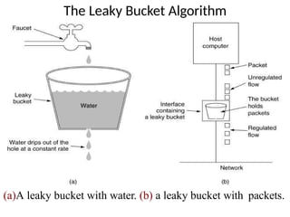
- 353. The Leaky Bucket Algorithm • The Leaky Bucket Algorithm used to control rate in a network. It is implemented as a single- server queue with constant service time. If the bucket (buffer) overflows then packets are discarded.
- 354. The Leaky Bucket Algorithm (a)A leaky bucket with water. (b) a leaky bucket with packets.
- 355. Token Bucket Algorithm • In contrast to the LB, the Token Bucket Algorithm, allows the output rate to vary, depending on the size of the burst. • In the TB algorithm, the bucket holds tokens. To transmit a packet, the host must capture and destroy one token. • Tokens are generated by a clock at the rate of one token every sec. • Idle hosts can capture and save up tokens (up to the max. size of the bucket) in order to sendlarger bursts later.
- 356. The Token B5-u34cket Algorithm (a) Before. (b) After.
- 357. Transmission Control Protocol TCP is receive r reliable protocol. always sends either positive That is, the or negative acknowledgementabout the data packet to the sender It ensures the data packet is reached the destination or it needs to resend it. TCP provides end-to-end communication. TCP provides full duplex server T C P I P I n t e r n e t w o r k By teSt r e a m By teS tr e a m T C P
- 358. Well-known ports used by TCP
- 359. Figure : TCP segment format
- 360. TCP Header The length of TCP header is minimum 20 bytes long and maximum 60 bytes. Source Port (16-bits) - It identifies source port of the application process on the sending device. Destination Port (16-bits) - It identifies destination port of the application process on the receiving device. Sequence Number (32-bits) - Sequence number of data bytes of a segment in a session.
- 361. Acknowledgement Number (32- bits) - When ACK flag is set, this number contains the next sequence number of the data byte expected and works as acknowledgement of the previous data received. Data Offset (4-bits) - This field implies both, the size of TCP header (32-bit words) and the offset of data in current packet in the whole TCP segment. Reserved (3-bits) - Reserved for future use and all are set zero by default.
- 362. Flags (1-bit each) NS - Nonce Sum bit is used by Explicit Congestion Notification signaling process. CWR - When a host receives packet with ECE bit set, it sets Congestion Windows Reduced to acknowledge that ECE received. ECE - If SYN bit is clear to 0, then ECE means that the IP packet has its CE (congestion experience) bit set.
- 363. URG - It indicates that Urgent Pointer field has significant data and should be processed. ACK - It indicates that Acknowledgement field has significance. If ACK is cleared to 0, it indicates that packet does not contain any acknowledgement. PSH - When set, it is a request to the receiving station to PUSH data (as soon as it comes) to the receiving application without buffering it.
- 364. RST - Reset flag has the following features: It is used to refuse an incoming connection. It is used to reject a segment. It is used to restart a connection. SYN - This flag is used to set up a connection between hosts. FIN - This flag is used to release a connection and no more data is exchanged thereafter. Because packets with SYN and FIN flags have sequence
- 365. Windows Size - This field is used for flow control between two stations and indicates the amount of buffer (in bytes) the receiver has allocated for a segment, i.e. how much data is the receiver expecting. Checksum - This field contains the checksum of Header, Data and Pseudo Headers. Urgent Pointer - It points to the urgent data byte if URG flag is set to 1.
- 366. Options - It facilitates additional options regula r which are not covered by the header. Option field is always described in 32- bit words. If this field contains data less than 32-bit, padding is used to cover the remaining bits to reach 32-bit boundary.
- 367. Connection Management in TCP Opening a TCP Connection Closing a TCP Connection Special Scenarios State Diagram
- 368. TCP Connection Establishment TCP uses a three-way handshake to open a connection: (1) ACTIVE OPEN: Client sends a segment with SYN bit set * port number of client initial sequence number (ISN) of client (2) PASSIVE OPEN: Server responds with a segment with SYN bit set * initial sequence number of server ACK for ISN of client (3) Client acknowledges by sending a segment with: ACK ISN of server(* counts as one byte)
- 369. Figure : Connection establishment using three-way handshaking
- 370. Figure : Connection termination using three-way handshaking
- 371. The User Datagram Protocol (UDP) is called a connectionless, unreliable transport protocol. It does not add anything to the services of IP except to provide process-to-process communication instead of host-to- host communication. •provide unreliable service
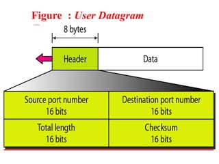
- 372. Table : Well-known ports used with UDP
- 373. Figure : User Datagram Format
- 374. UDP Format Source and destination port : 16, 16 identify applications at ends of the connection length: 16 - length of datagram including header and data checksum :16 -one’s complement of header and data including pseudo data
- 375. UDP for Application TFTP DNS RPC, NFS SNMP
- 376. Figure :Pseudo header for checksum calculation
- 377. Figure : Queues in UDP
- 378. TCP UDP Transmission Control Protocol User Datagram Protocol Connection Oriented Connection Less Slow Fast Highly Reliable Unreliable 20 Bytes 8 Bytes It takes acknowledgement of data and has the ability to retransmit if the user requests. It neither takes acknowledgement, nor it retransmits the lost data. TCP is heavy-weight. UDP is lightweight.
- 379. Stream-based Message-based Delivery of all data is managed Not performed Flow control using sliding window protocol None TCP doesn’t supports Broadcasting. UDP supports Broadcasting. Small to moderate amounts of data Small to enormous amounts of the data Applications where reliable transmission of data matters. Application where data delivery speed matters. FTP , Telnet, SMTP , IMAP. DNS, BOOTP, DHCP, TFTP.
- 380. • A protocol is designed to handle real-time traffic (like audio and video) of the Internet, is known as Real Time Transport Protocol (RTP). • RTP must be used with UDP. • It does not have any delivery mechanism like multicasting or port numbers. • RTP supports different formats of files like MPEG and MJPEG.
- 381. • It is very sensitive to packet delays and less sensitive to packet loss. • RTP is first time published in 1996 and known as RFC 1889. And next it published in 2003 with name of RFC 3550.
- 382. 1. RTP mainly helps in media mixing, sequencing and time-stamping. 2. Voice over Internet Protocol (VoIP) 3. Video Teleconferencing over Internet. 4. Internet Audio and video streaming.
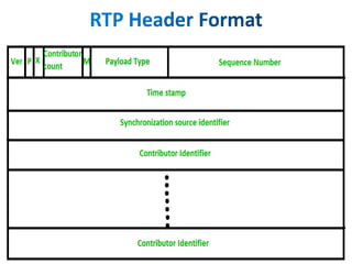
- 384. • Version : This 2-bit field defines version number. The current version is 2. • P –The length of this field is 1-bit. If value is 1, then it denotes presence of padding at end of packet and if value is 0, then there is no padding. • X –The length of this field is also 1-bit. If value of this field is set to 1, then its indicates an extra extension header between data and basic header and if value is 0 then, there is no extra extension. • Contributor count –This 4-bit field indicates number of contributors. Here maximum possible number of contributor is 15 as a 4-bit field can allows number form 0 to 15. • M –The length of this field is 1-bit and it is used as end marker by application to indicate end of its data. • Payload types –This field is of length 7-bit to indicate type of payload. We list applications of some common types of payload.
- 385. • Sequence Number –The length of this field is 16 bits. It is used to give serial numbers to RTP packets. • Time Stamp –The length of this field is 32-bit. It is used to find relationship between times of different RTP packets. • Synchronization Source Identifier –This is a 32-bit field used to identify and define the source. The value for this source identifier is a random number that is chosen by source itself. • Contributor Identifier –This is also a 32-bit field used for source identification where there is more than one source present in session.
- 386. THANK YOU
- 387. UNIT V APPLICATIONS Applications - DNS – E-Mail Protocols – WWW – SNMP – SMTP - Security – Threats and Services- Cryptography -DES- RSA- Web security -SSL .
- 389. OVERVIEW • Applications • DNS • E-Mail Protocol • WWW • SNMP • SMTP • Security • Threats and Services • Cryptography • DES • RSA • Web security • SSL
- 390. • An application layer is an abstraction layer that specifies the shared communications protocols and interface methods used by hosts in a communications network. • The application layer abstraction is used in both of the standard models of computer networking. • The Internet Protocol Suite (TCP/IP) and the OSI model. • Although both models use the same term for their respective highest-level layer.
- 391. Services of Application Layers • File Transfer • Addressing • Mail Services • Directory Services • Authentication
- 392. • (Domain Name DNS System) The Internet's system for converting alphabetic names into numeric IP addresses. • For example, when a Web address (URL) is typed into a browser, DNS servers return the IP address of the Web server associated with that name. • In this example, the DNS converts the URL www.company.com into the IP address 204.0.8.51.
- 393. A Hierarchy of Servers • The DNS system is a hierarchy of duplicated database servers worldwide that begin with the "root servers" for the top-level domains (.com, .net, .org, .gov, .edu, .mil, etc.). The root servers point to the "authoritative" servers located in ISPs, www.yahoo.com www --------> Host Name Yahoo--------> Server Name com ----------> Domain Name
- 394. Structure of DNS • It Consists of Four Elements 1. DNS Name Space 2. DNS Database 3. Name Servers 4. DNS Resolvers
- 395. 1. DNS Name Space • The Domain Name Space consists of a tree data structure. • Each node or leaf in the tree has a label and zero or more resource records (RR), which hold information associated with the domain name. • The domain name itself consists of the label, parent node on the right. • The tree sub-divides into zones beginning at the A DNS zone may consist of only one domain, or may consist of many domains and sub- domains, depending on the administrative choices
- 397. 2. DNS Database • DNS does not only deal with IP addresses of hosts, but also exchanges information on Name Servers. • The Key features of the Database are as Follows : 1) Variable-Depth Hierarchy for Names. 2) Distributed Database. 3) Distribution Controlled by Database.
- 398. 3. Name Servers • The Domain Name System is maintained by a distributed database system, which uses the client–server model. • The nodes of this database are the name servers. • Each domain has at least one authoritative DNS server that publishes information about that domain and the name servers of any domains subordinate to it. • The top of the hierarchy is served by the root name servers.
- 399. 4. DNS Resolvers • The client side of the DNS is called a DNS resolver. • A resolver is responsible for initiating and sequencing the queries that ultimately lead to a full resolution. • DNS resolvers are classified by a variety of query methods, such as recursive, non-recursive, and iterative.
- 400. • The DNS protocol uses two types of DNS messages, queries and replies; both have the same format. • Each message consists of a header and four sections: question, answer, authority, and an additional space. • A header field (flags) controls the content of these four sections. • The header section consists of the following fields: Identification, Flags, Number of questions, Number of answers, Number of authority resource records (RRs), and Number of additional RRs. Each field is 16
- 401. • Primary website. • Marketing campaign websites. • Email servers. • Customer support websites. • Online resource libraries. • Inside sales web portals. • Multi-tier web applications. • P2P resources.
- 402. • Electronic Mail or E-Mail is a method of sending and receiving messages (Mail) electronically over a Computer Network. • E-Mail is a system allows a person or a group to electronically communicate to others through Internet. • It is method of exchanging message between people using electronic devices. • Exchanging message as Text files and non-text files (images, graphics Image, files so on.,)
- 403. Components of Email System Mail Server Receive, Store and Deliver the mail DNS Find and match the IP Address of the Mail Server Mailbox It is a Folder contains Emails and their information.
- 404. E-Mail Protocol The E-Mail communication is three protocols in general. They are, done via 1.SMTP ( Simple Mail Transfer Protocol) 2.POP ( Post Office Protocol) 3.IMAP ( Internet Mail Access Protocol)
- 405. SMTP (Simple Mail Transfer Protocol) The SMTP stands for Simple Mail Transfer Protocol. Email is sent using this protocol. Is an internet standard communication protocolfor electronic mail transmission. Mail servers and other message transfer agents use SMTP to send and receive mail messages.
- 406. ADVANTAGES: SMTP provides the simplest form of communicating through email message between various computers in a particular network. Since SMTP is developed from a simple platform , email messages may be sent easily and quickly. SMTP also offers reliability in terms of outgoing email messages. DISADVANTAGES: The main drawback of sending through an SMTP server is that it is insecure, it can be easily hacked. Another disadvantage is the server limitation.
- 407. POP (Post Office Protocol): This protocol is also used for incoming emails. The main difference with the both protocols is that POP downloads the entire email into the local computer and deletes the data on the server once it is downloaded. This is helpful in a server with less free memory. Current version of POP is POP3 .
- 408. ADVANTAGES: Emails are downloaded to the user`s computer. opening attachments is quick and easy as they are already downloaded. Less server storage space required all emails are stored on local machine. Storage capacity of emails limited by the size of your hard disk. very popular, easy to configure and use. DISADVANTAGES: Emails cannot be accessed from other machines(unless configured to do so). Exporting the local mail folder to another email client or physical machine can be difficult. Email folders can become corrupted, potentially losing the entire mailbox at once.
- 409. IMAP(Internet Mail Access Protocol) This protocol is used while receiving an email. When one uses IMAP, the emails will be present in the server and not get downloaded to the user`s mail box and deleted from the server. This helps to have less memory used in the local computer and server memory is increased.
- 410. ADVANTAGES: Mail stored on remote server, i.e. accessible from multiple different location. Internet connection needed to access mail. Mail is automatically backed up if server is managed properly. DISADVANTAGES: The main disadvantage of the IMAP protocols is that it is mandatory to have an internet connection on all the time to read/reply and search the message.
- 411. WWW • The World Wide Web is the universe of network- accessible information. • In simple terms, The World Wide Web is a way of exchanging information between computers on the Internet. • The World Wide Web is based on several different Technologies : Web browsers, Hypertext Markup Language (HTML) and Hypertext Transfer Protocol (HTTP).
- 412. Features of WWW • HyperText Information System • Cross-Platform • Distributed • Open Standards and Open Source • Uses Web Browsers to provide a single interface for many services • Dynamic, Interactive and Evolving. • “Web 2.0”
- 413. Components of WWW • There are 5 Components of WWW: 1.Uniform Resource Locator (URL): serves as system for resources on web. 2.HyperText Transfer Protocol (HTTP): specifies communication of browser and server. 3.Hyper Text Markup Language (HTML): It Defines structure, organisation and content of webpage. 4.Web Server : A web server is computer software and underlying hardware that accepts requests via HTTP, the network protocol created to distribute web pages.
- 414. Components of WWW 5.Web Browser : A web browser (commonly referred to as a browser or internet browser). • It is an application software for accessing the World Wide Web. • When a user requests a web page from a particular website, the web browser retrieves the necessary content from a web server and then displays the page on the user's device.
- 415. WWW Architecture
- 416. Working of WWW • The World Wide Web is based on several different technologies : 1. Web browser. 2. Hypertext Markup Language (HTML). 3. Hypertext Transfer Protocol (HTTP). 1. Web browser : It is used to access webpages. Web browsers can be defined as programs which display text, data, pictures, animation and video on the Internet.
- 417. 2.HTML : Hyperlinked resources on the World Wide Web can be accessed using software interface provided by Web browsers. 3.HTTP : It can be used for several tasks including : searches, mailing, transferring files, and much more. Some of the commonly used browsers are Internet Explorer, Opera Mini, Google Chrome.
- 418. • Online Forms • Shopping Carts • Word Processors • Spreadsheets • Video and Photo Editing • File Conversion • File Scanning • E-mail programs such as Gmail, Yahoo and AOL. • Popular Applications include Google Apps and Microsoft 365.
- 419. SNMP • Simple Network Management Protocol (SNMP) is an application–layer protocol defined by the • It is a part Protocol⁄Internet suite. of Transmission Control Protocol (TCP⁄IP) protocol • SNMP is one of the widely accepted network protocols to manage and monitor network elements.
- 420. SNMP consists of
- 421. • GET: The GET operation is a request sent by the manager to the managed device. • GET NEXT: The significant difference is that the GET NEXT operation retrieves the value of the next MIB tree. • GET BULK: The GETBULK operation is used to retrieve voluminous data from large MIB table. • SET: This operation is used by the managers to modify or assign the value of the Managed device. • TRAPS: TRAPS are initiated by the Agents. It is a signal to the SNMP Manager by the Agent on the occurrence of an event. • INFORM: It includes confirmation from the SNMP manager on receiving the message. • RESPONSE: It is the command used to carry back the value(s) or signal of actions directed by the SNMP Manager.
- 423. • SMTP stands for Simple Mail Transfer Protocol. • SMTP is a set of communication guidelines that allow software to transmit an electronic mail over the internet is called Simple Mail Transfer Protocol. • It is a program used for sending messages to other computer users based on e-mail addresses.
- 424. • It provides a mail exchange between users on the same or different computers, and it also supports: 1. It can send a single message to one or more recipients. 2. Sending message can include text, voice, video or graphics. 3. It can also send the messages on networks outside the internet. 4. The main purpose of SMTP is used to set up communication rules between servers.
- 427. • It have the following Working Functionalities : 1. Composition of Mail 2. Submission of Mail 3. Delivery of Mail 4. Receipt and Processing of Mail 5. Access and Retrieval of Mail
- 428. ADVANTAGES: SMTP provides the simplest form of communicating through email message between various computers in a particular network. Since SMTP is developed from a simple platform , email messages may be sent easily and quickly. SMTP also offers reliability in terms of outgoing email messages. DISADVANTAGES: The main drawback of sending through an SMTP server is that it is insecure, it can be easily hacked. Another disadvantage is the server limitation.
- 429. • Network Security deals with all aspects related to the protection of the sensitive information assets existing on the network. • It covers various mechanisms developed to provide fundamental security services for data communication. • It describes the functioning of most common security protocols employed at different networking layers right from application to data link layer.
- 430. Goals of Network Security of network security are • The primary goal Confidentiality, three pillars of Network Security are Integrity, and Availability. These often represented as CIA triangle. 1.Confidentiality − The function of confidentiality is to protect precious business data from unauthorized persons. 2.Integrity − It means maintaining and assuring the accuracy and consistency of data. The function of integrity is to make sure that the data is reliable and is not changed by unauthorized persons.
- 431. 3. Availability − The function of availability in Network Security is to make sure that the data, network resources/services are continuously available to the users, whenever they require it.
- 432. Security Services fundamental security services as the following − 1.Confidentiality − E-mail message should not be read by anyone but the intended recipient. 2.Authentication − E-mail recipient can be sure of the identity of the sender. 3.Integrity − Assurance to the recipient that the e- mail message has not been altered since it was transmitted by the sender. 4.Non-repudiation − E-mail recipient is able to prove to a third party that the sender really did send the message.
- 433. 5. Proof of submission − E-mail sender gets the confirmation that the message is handed to the mail delivery system. 6. Proof of delivery − Sender gets a confirmation that the recipient received the message.
- 434. Threats and Services A Computer System Threat is anything that leads to loss or corruption of data or physical damage to the hardware or infrastructure. • Security Threats can be many like Software attacks, theft of intellectual property, identity theft, theft of equipment or information. • Threat is any activity that can lead to data loss/corruption through to delay of normal business operations.
- 435. Types of Threats • There are physical and non-physical threats. • Physical Threats : cause damage to computer systems hardware and infrastructure. Examples include theft, vandalism through to natural disasters. • Non-physical Threats : Target the software and data on the computer systems.
- 436. • A physical threat is a potential cause of an incident that may result in loss or physical damage to the computer systems. • The following list classifies the physical threats into three main categories • Internal: The threats include fire, unstable power supply, humidity in the rooms housing the hardware, etc. • External: These threats include Lightning, floods, earthquakes, etc. • Human: These threats include theft, vandalism of the infrastructure and hardware, accidental or intentional errors.
- 437. The following list is the common types of non-physical threats; • Virus • Trojans • Worms • Spyware • Key loggers • Adware • Denial of Service Attacks • Distributed Denial of Service Attacks • Unauthorized access to computer systems resources such as data • Phishing • Other Computer Security Risks
- 438. Cryptography • Cryptography is a method of protecting information and communications through the use of codes. • The information is intended can read and process it. • The prefix "crypt-" means "hidden" or "vault" -- and the suffix "-graphy" stands for "writing." • Cryptography refers to secure information and communication techniques derived from mathematical concepts and a set of rule- based calculations called algorithms.
- 439. Cryptography Techniques • Cryptography is closely related to the disciplines of • It includes techniques such as microdots, merging words with images, and other ways to hide information in storage or transit. • Cryptography is used to convert Plaintext into Ciphertext is known as Encryption. then back again • Encryption : Known to Unknown • Decryption : Unknown to Known
- 441. • Cryptography concerns with the following Four objectives: the information cannot be understood by anyone for whom it was unintended. the information cannot be altered in storage or transit between sender and intended receiver without the alteration being detected.
- 442. the creator/sender of the information cannot deny at a later stage his or her intentions in the creation or transmission of the information. the sender and receiver can confirm each other's identity and the origin/destination of the information.
- 443. 1. Single-key or Symmetric-key Cryptography. 2. Public-key or Asymmetric-key Cryptography. 1. Single-key or Symmetric-key Cryptography : Symmetric cryptography is based on the use of just is used to both Encrypt and Decrypt the messages ( only Private Key or Secret Key ) 2. Public-key or Asymmetric-key Cryptography : Asymmetric cryptography, also known as public-key cryptography, Here Two keys are used to Encrypt and Decrypt the messages (Both Private and Public Key)
- 447. • The Data Encryption Standard is a symmetric-key algorithm for the encryption of digital data. • The DES (Data Encryption Standard) algorithm is a symmetric-key block cipher created in the early 1970s by an IBM team and adopted by the National Institute of Standards and Technology (NIST). • DES is an implementation of a Feistel Cipher. It uses 16 round Feistel structure. • Key length is 64-bit. • Since DES is based on the Feistel Cipher. 1. Round function. 2. Key schedule. 3. Any additional processing − Initial and final permutation.
- 449. • The algorithm process breaks down into the following steps: 1.The process begins with the 64-bit plain text block getting handed over to an initial permutation (IP) function. 2.The initial permutation (IP) is then performed on the plain text. 3.Next, the initial permutation (IP) creates two halves of the permuted block, referred to as Left Plain Text (LPT) and Right Plain Text (RPT). 4.Each LPT and RPT goes through 16 rounds of the encryption process. 5.Finally, the LPT and RPT are rejoined, and a Final Permutation (FP) is performed on the newly combined block. 6.The result of this process produces the desired 64-bit ciphertext.
- 450. • The DES satisfies both the desired properties of block cipher. These two properties make cipher very strong. • Avalanche effect − A small change in plaintext results in the very great change in the ciphertext. • Completeness − Each bit of ciphertext depends on many bits of plaintext.
- 451. • You must choose a security provider to implement your data encryption algorithm. • There are many available providers to choose from, but selecting one is the essential initial step in implementation. • Your selection may depend on the language you are using,
- 452. • RSA (Rivest–Shamir–Adleman) is a public-key cryptosystem that is widely used for secure data transmission. • In a public-key cryptosystem, the encryption key is public and distinct from the decryption key, which is kept secret (private). • RSA algorithm is asymmetric cryptography algorithm. Asymmetric actually means that it works on two different keys i.e. Public Key and Private Key. As the name describes that the Public Key is given to everyone and Private key is kept private.
- 453. Example : • A client (for example browser) sends its public key to the server and requests for some data. • The server encrypts the data using client’s public key and sends the encrypted data. • Client receives this data and decrypts it.
- 455. The RSA algorithm holds the following features − • RSA algorithm is a popular exponentiation in a finite field over integers including prime numbers. • The integers used by this method are sufficiently large making it difficult to solve. • There are two sets of keys in this algorithm: private key and public key.
- 456. • The following steps to work on RSA algorithm : The initial procedure begins with selection of two prime numbers namely p and q, and then calculating their product N, N=p*q Consider number e as a derived number which should be greater than 1 and less than (p-1) and (q-1). The specified pair of numbers n and e forms the RSA public key and it is made public.
- 457. Private Key d is calculated from the numbers p, q and e. The mathematical relationship between the numbers is as follows :
- 458. Encryption Formula Consider a sender who sends the plain text message to someone whose public key is (n,e). To encrypt the plain text message in the given scenario, use the following syntax − Decryption Formula • The decryption process is very straightforward and includes analytics for calculation in a systematic approach. Considering receiver C has the private key d, the result modulus will be calculated as −
- 459. known as • Web security “Cybersecurity”. is also It basically means protecting a website or web application by detecting, preventing and responding to cyber threats. • web security is easy to install and it also helps the business people to make their website safe and secure. • A web application firewall prevents automated attacks that usually target small or lesser-known websites.
- 462. • Secure Sockets Layer (SSL) is a security protocol that authentication, and provides privacy, integrity to Internet communications. • SSL eventually evolved into Transport Layer Security (TLS). • SSL, or Secure Sockets Layer, is an encryption-based Internet security protocol. It was first developed by Netscape in 1995.
- 463. • SSL encrypts data that is transmitted across the web. • SSL initiates an authentication process called a handshake between two communicating devices to ensure that both devices are really who they claim to be. • SSL also digitally signs data provide data integrity. in order to
- 464. • SSL supports the following information security principles: 1. Encryption: protect data transmissions (e.g. browser to server, server to server, application to server, etc.) 2.Authentication: ensure the server you’re connected to is actually the correct server. 3.Data integrity: ensure that the data that is requested or submitted is what is actually delivered.
- 465. THANK YOU