
![PrefaceAugust 2011 Series
Preface
This guide is a Cisco® Smart Business Architecture (SBA) guide.
Who Should Read This Guide
This guide is written for people who fill a variety of roles:
• Systems engineers who need standard procedures for implementing
solutions
• Project managers who need reference material for creating statements
of work for SBA implementations
• Sales partners who want help with selling new technology or who create
their own implementation documentation
• Trainers who need material for classroom instruction or on-the-job
training
In general, you can also use SBA guides to improve consistency among
engineers, among deployments, and to improve scoping and costing of
deployment jobs.
Release Series
Cisco updates and enhances SBA guides twice a year. Before we release a
series of SBA guides, we test them together in the SBA lab, as a complete
system. To ensure the mutual compatibility of designs in SBA guides, you
should use guides that belong to the same SBA series.
All SBA guides include the series name on the cover and at the bottom left
of each page. The series are named as follows:
• February year Series
• August year Series
where year indicates the calendar year of the series.
You can find the most recent series of SBA guides at the following sites:
Customer access: http://www.cisco.com/go/sba
Partner access: http://www.cisco.com/go/sbachannel
How to Read Commands
Many SBA guides provide specific details about how to configure Cisco net-
work devices that run Cisco IOS, Cisco NX-OS, or other operating systems
that you configure at a command-line interface (CLI). This section describes
the conventions used to specify commands that you must enter.
Commands to enter at a CLI appear as follows:
configure terminal
Commands that specify a value for a variable appear as follows:
ntp server 10.10.48.17
Commands with variables that you must define appear as follows:
class-map [highest class name]
Commands shown in an interactive example, such as a script or when the
command prompt is included, appear as follows:
Router# enable
Long commands that line wrap are underlined. Enter them as one command:
wrr-queue random-detect max-threshold 1 100 100 100 100 100
100 100 100
Comments and Questions
If you would like to comment on a guide or ask questions, please use the
forum at the bottom of one of the following sites:
Customer access: http://www.cisco.com/go/sba
Partner access: http://www.cisco.com/go/sbachannel
An RSS feed is available if you would like to be notified when new comments
are posted.](https://image.slidesharecdn.com/presentation-datacenterdeploymentguide-150728034823-lva1-app6891/85/Presentation-data-center-deployment-guide-2-320.jpg)


![9Ethernet InfrastructureAugust 2011 Series
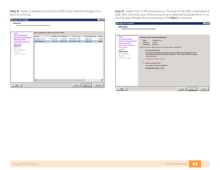
Initial Setup
1. Establish Physical Connectivity
2. Perform Initial Device Configuration
Process
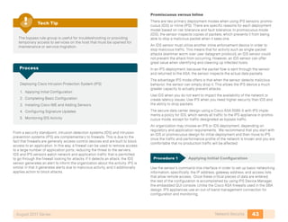
Procedure 1 Establish Physical Connectivity
Complete the physical connectivity of the Cisco Nexus 5000 Series switch
pair according to the illustration in Figure 2. (or according to the specific
requirements of your implementation).
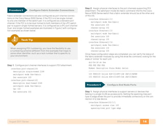
Step 1: Connect ports Ethernet 1/17 and 1/18 or other available Ethernet
ports between the two Cisco Nexus 5000 Series switches. This link will be
used as the vPC peer-link, which allows the peer connection to form and
supports forwarding of traffic between the switches if necessary during a
partial link failure of one of the vPC port channels.
Step 2: Connect the Management 0 ports to the SBA core switch pair (or an
alternate location where they can be connected to the data center manage-
ment VLAN). In our example configurations, the data center management
VLAN is 163.
Step 3: Connect ports Ethernet 1/19 and 1/20 or other available Ethernet
ports on each Cisco Nexus 5000 Series switch to the SBA core to build the
port channel which will carry production data traffic. Four 10 gigabit Ethernet
connections will provide an aggregate throughput of 40 Gbps to carry data
back and forth to client machines, or to be Layer-3 switched between serv-
ers by the SBA core if required.
Step 4: To support a dual-homed FEX with single-homed servers, connect
fabric uplink ports 1 and 2 on the FEX to port Ethernet 1/13 or other available
Ethernet ports, one on each Cisco Nexus 5000 Series switch. These ports
will operate as a port channel to support the dual-homed FEX configuration.
Step 5: Support single-homed FEX attachment by connecting fabric uplink
ports 1 and 2 on each FEX to ports Ethernet 1/15 and 1/16 or other available
Ethernet ports on only one member of the Cisco Nexus 5000 Series switch
pair. These ports will be a port-channel, but will not be configured as a vPC
port-channel, because they have physical ports connected to only one
member of the switch pair.
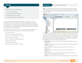
Procedure 2 Perform Initial Device Configuration
Step 1: Connect a terminal cable to the console port of the first Cisco
Nexus 5000 Series switch, and power on the system to enter the initial
configuration dialog.
Step 2: Follow the Basic System Configuration Dialog for initial device
configuration of the first Cisco Nexus 5000 Series switch, as shown in the
terminal capture below:
Do you want to enforce secure password standard (yes/no): y
Enter the password for “admin”:
Confirm the password for “admin”:
---- Basic System Configuration Dialog ----
This setup utility will guide you through the basic
configuration of the system. Setup configures only enough
connectivity for management of the system.
Please register Cisco Nexus 5000 Family devices promptly with
your supplier. Failure to register may affect response times
for initial service calls. Nexus devices must be registered to
receive entitled support services.
Press Enter at anytime to skip a dialog. Use ctrl-c at anytime
to skip the remaining dialogs.
Would you like to enter the basic configuration dialog (yes/
no): y
Create another login account (yes/no) [n]: n
Configure read-only SNMP community string (yes/no) [n]: n
Configure read-write SNMP community string (yes/no) [n]: n
Enter the switch name : dc3-5k-1
Continue with Out-of-band (mgmt0) management configuration?
(yes/no) [y]: y](https://image.slidesharecdn.com/presentation-datacenterdeploymentguide-150728034823-lva1-app6891/85/Presentation-data-center-deployment-guide-13-320.jpg)
![10Ethernet InfrastructureAugust 2011 Series
Mgmt0 IPv4 address : 10.10.63.10
Mgmt0 IPv4 netmask : 255.255.255.0
Configure the default gateway? (yes/no) [y]: y
IPv4 address of the default gateway : 10.10.63.1
Enable the telnet service? (yes/no) [n]: y
Enable the http-server? (yes/no) [y]: y
Enable the ssh service? (yes/no) [y]: y
Type of ssh key you would like to generate (dsa/rsa) : rsa
Number of key bits <768-2048> : 2048
Configure the ntp server? (yes/no) [n]: y
NTP server IPv4 address : 10.10.48.17
Enter basic FC configurations (yes/no) [n]: n
The following configuration will be applied:
switchname dc2-5k-1
interface mgmt0
ip address 10.10.63.10 255.255.255.0
no shutdown
exit
vrf context management
ip route 0.0.0.0/0 10.10.63.1
exit
telnet server enable
feature http-server
ssh key rsa 768 force
ssh server enable
ntp server 10.10.48.17 use-vrf management
Would you like to edit the configuration? (yes/no) [n]: n
Use this configuration and save it? (yes/no) [y]: y
[########################################] 100%
Nexus 5000 Switch
dc2-5k-1 login:
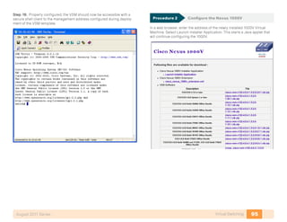
Step 3: Enable common required features in the NXOS software. The
example configurations shown in this guide use the following features:
feature telnet
feature private-vlan
feature udld
feature interface-vlan
feature lacp
feature vpc
feature lldp
feature fex
feature npv
If Fibre Channel–specific features such as Fibre Channel over
Ethernet (FCoE) or N-Port Virtualization (NPV) are required, they
should be enabled prior to applying any additional configura-
tion to the switch. The NPV feature requires you to re-apply any
existing configuration commands to the switch if it is added or
removed.
Tech Tip
Step 4: Create required VLANs. For our example configuration, we are
using VLANS 148-163 for various roles within the data center, and VLAN 999
as a “dummy” VLAN to define as native on trunks to mitigate the risk of any
VLAN hopping by untagged traffic. It is helpful to assign names to VLANs as
they are created; this makes the switch configuration more self-documenting
and can assist later if troubleshooting is required.
vlan 148
name servers1
vlan 149
name servers2
vlan 163
name dc-management
vlan 999
name native](https://image.slidesharecdn.com/presentation-datacenterdeploymentguide-150728034823-lva1-app6891/85/Presentation-data-center-deployment-guide-14-320.jpg)

![12Ethernet InfrastructureAugust 2011 Series
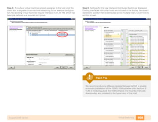
Step 5: Add physical interfaces to the trunk and connect the two Nexus
5000s’ ports together. A minimum of two physical interfaces is recom-
mended for link resiliency. Different 10 gigabit Ethernet ports (as required
by your specific implementation) may replace the interfaces shown in the
example.
interface Ethernet1/17
description vpc peer link
switchport mode trunk
channel-group 10 mode active
interface Ethernet1/18
description vpc peer link
switchport mode trunk
channel-group 10 mode active
Step 6: Repeat ste 151 a 153 throug515 for the secondary Nexus 5000. In
st 153, be sure to swap the destination and source addresses.
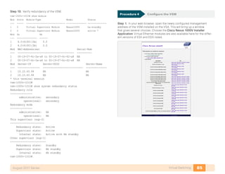
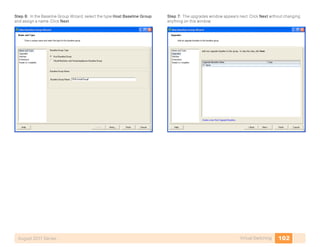
Step 7: Before moving on to the next procedure, ensure that the vPC peer
relationship has formed successfully using the “show vpc” command.
dc3-5k-1# show vpc
Legend:
(*) - local vPC is down, forwarding via vPC peer-link
vPC domain id : 10
Peer status : peer adjacency formed ok
vPC keep-alive status : peer is alive
Configuration consistency status: success
vPC role : secondary
Number of vPCs configured : 86
Peer Gateway : Disabled
Dual-active excluded VLANs : -
vPC Peer-link status
--------------------------------------------------------------
id Port Status Active vlans
-- ---- ------ -------------------------------------------
1 Po10 up 1,148-163,520,999
Look for the peer status of “peer adjacency formed ok” and the keep-alive
status of “peer is alive” to verify successful configuration. If the status
does not indicate success, double-check the IP addressing assigned for
the keep-alive destination and source addresses, as well as the physical
connections.
Do not be concerned about the “(*) - local vPC is down, forwarding
via vPC peer-link” statement at the top of the command output.
Once you have vPC port channels defined, this is a legend to
show the meaning of an asterisk next to your port channel in the
listing if one of its member links is down.
Tech Tip
Procedure 2 Create Port Channel to SBA Core
A port-channel interface needs to be created to carry traffic back and forth
to the network core, which provides forwarding to client machines and
layer-3 forwarding between the different IP subnets carried on different
VLANs. We recommend at least two physical interfaces from each vPC peer
switch connected to the network core, for a total port channel of four resilient
physical 10 gigabit Ethernet links and 40Gbps of throughput. Defining a vPC
port channel is identical to defining a standard port channel interface, with
the addition of the “vpc [port-channel no.]” command added to the interface
configuration.
Step 1: On both of the Data Center Nexus 5000 vPC members, define
EtherChannel configuration:
interface port-channel60
description link to core
switchport mode trunk
vpc 60
switchport trunk native vlan 999
switchport trunk allowed vlan 148-153,156-163
interface Ethernet1/19
description link to core
switchport mode trunk
switchport trunk native vlan 999
switchport trunk allowed vlan 148-153,156-163
channel-group 60 mode active](https://image.slidesharecdn.com/presentation-datacenterdeploymentguide-150728034823-lva1-app6891/85/Presentation-data-center-deployment-guide-16-320.jpg)
![13Ethernet InfrastructureAugust 2011 Series
interface Ethernet1/20
description link to core
switchport mode trunk
switchport trunk native vlan 999
switchport trunk allowed vlan 148-153,156-163
channel-group 60 mode active
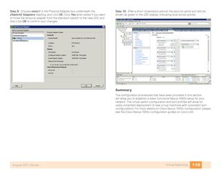
Step 2: On the SBA Midsize Core Switch, define an equivalent
EtherChannel configuration:
vlan 153
name Secure-DC-outside
!
vlan 154
name Secure-DC-inside-1
!
vlan 155
name Secure-DC-inside-2
!
vlan 159
name 1kv-packet
!
vlan 160
name 1kv-control
!
vlan 161
name vmotion
!
vlan 162
name iscsi
!
vlan 163
name dc-management
!
interface Port-channel60
description Connection to DC-5K-2K
switchport
switchport trunk encapsulation dot1q
switchport trunk native vlan 999
switchport trunk allowed vlan 148-153,156-163
switchport mode trunk
!
interface TenGigabitEthernet1/4/15
description Connection to DC-5K-2K
switchport
switchport trunk native vlan 999
switchport trunk allowed vlan 148-153,156-163
switchport mode trunk
channel-group 60 mode active
macro apply EgressQoS
!
interface TenGigabitEthernet1/4/16
[same as TenGigabitEthernet1/4/15]
!
interface TenGigabitEthernet2/4/15
[same as TenGigabitEthernet1/4/15]
!
interface TenGigabitEthernet2/4/16
[same as TenGigabitEthernet1/4/15]
!
interface Vlan153
description Secure DC outside
ip address 10.10.53.1 255.255.255.128
!
interface Vlan154
description DC Secure VLAN: Assign no IP Address
no ip address
!
interface Vlan155
description DC Secure VLAN: Assign no IP Address
no ip address
!
interface Vlan163
description DC Management
ip address 10.10.63.1 255.255.255.0](https://image.slidesharecdn.com/presentation-datacenterdeploymentguide-150728034823-lva1-app6891/85/Presentation-data-center-deployment-guide-17-320.jpg)


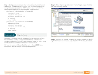
![19Storage InfrastructureAugust 2011 Series
When initially powered on, a new Cisco MDS 9148 switch starts a setup
script when accessed from the console.
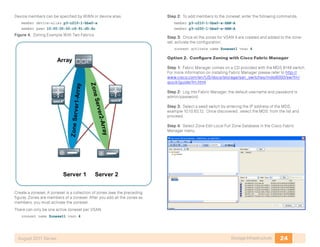
Step 1: Follow the prompts in the setup script to configure login, out-of-
band management, Telnet, SSH, clock, time zone, Network Time Protocol,
switch port modes, and default zone policies.
When the administrative login is configured, a Simple Network
Management Protocol Version 3 (SNMPv3) user is created auto-
matically. This login is used by Cisco Fabric Manager to manage
the switch. Also note, you will want to configure the secure pass-
word standard. The secure password standard does not allow
for creation of insecure passwords and should be used for all
production Cisco MDS switches.
Tech Tip
---- System Admin Account Setup ----
Do you want to enforce secure password standard (yes/no) [y]:
Enter the password for “admin”:
Confirm the password for “admin”:
---- Basic System Configuration Dialog ----
This setup utility will guide you through the basic
configuration of the system. Setup configures only enough
connectivity for management of the system.
Please register Cisco MDS 9000 Family devices promptly with
your supplier. Failure to register may affect response times
for initial service calls. MDS devices must be registered to
receive entitled support services.
Press Enter at anytime to skip a dialog. Use ctrl-c at anytime
to skip the remaining dialogs.
Would you like to enter the basic configuration dialog (yes/
no): y
Create another login account (yes/no) [n]:
Configure read-only SNMP community string (yes/no) [n]:
Configure read-write SNMP community string (yes/no) [n]:
Enter the switch name : p3-mds9148-1
Continue with Out-of-band (mgmt0) management configuration?
(yes/no) [y]:
Mgmt0 IPv4 address : 10.10.63.12
Mgmt0 IPv4 netmask : 255.255.255.0
Configure the default gateway? (yes/no) [y]:
IPv4 address of the default gateway : 10.10.63.1
Configure advanced IP options? (yes/no) [n]:
Enable the ssh service? (yes/no) [y]:
Type of ssh key you would like to generate (dsa/rsa) [rsa]:
Number of rsa key bits <768-2048> [1024]:
Enable the telnet service? (yes/no) [n]: y
Enable the http-server? (yes/no) [y]:
Configure clock? (yes/no) [n]:
Configure timezone? (yes/no) [n]:
Configure summertime? (yes/no) [n]:
Configure the ntp server? (yes/no) [n]: y
NTP server IPv4 address : 10.10.48.17
Configure default switchport interface state (shut/noshut)
[shut]: noshut
Configure default switchport trunk mode (on/off/auto) [on]:
Configure default switchport port mode F (yes/no) [n]:
Configure default zone policy (permit/deny) [deny]:
Enable full zoneset distribution? (yes/no) [n]:
Configure default zone mode (basic/enhanced) [basic]:
The following configuration will be applied:
switchname p3-mds9148-1
interface mgmt0
ip address 10.10.63.12 255.255.255.0
no shutdown
ip default-gateway 10.10.63.1
ssh key rsa 1024 force
feature ssh
feature telnet
feature http-server
ntp server 10.10.48.17
no system default switchport shutdown](https://image.slidesharecdn.com/presentation-datacenterdeploymentguide-150728034823-lva1-app6891/85/Presentation-data-center-deployment-guide-23-320.jpg)
![20Storage InfrastructureAugust 2011 Series
system default switchport trunk mode on
no system default zone default-zone permit
no system default zone distribute full
no system default zone mode enhanced
Would you like to edit the configuration? (yes/no) [n]: n
Use this configuration and save it? (yes/no) [y]: y
[########################################] 100%
Network Time Protocol (NTP) is critical to troubleshooting and
should not be overlooked.
Tech Tip
Step 2: The Cisco MDS Device Manager provides a graphical interface to
configure a Cisco MDS 9100 Family switch. To access the Device Manager,
connect to the management address via HTTP or access it directly through
Cisco Fabric Manager. The CLI can also be used to configure the MDS 9100
Family switch.
Java runtime environment (JRE) is required to run Cisco Fabric
Manager and Device Manager and should be installed before
accessing either application.
Tech Tip
Cisco Fabric Manager is a Java application available for download
from Cisco.com or from the CD that ships with the Cisco MDS
9100 Family switch. Managing more than one switch at the same
time requires licensing.
Tech Tip
Procedure 2 Configuring VSANs
By default, all ports are assigned to VSAN 1 at initialization of the switch. It is
a best practice to create a separate VSAN for production and to leave VSAN
1 for unused ports. By not using VSAN 1, you can avoid future problems
with merging of VSANs when combining other existing switches that may be
set to VSAN 1. To create a VSAN, use the command-line interface (CLI) or
Device Manager.
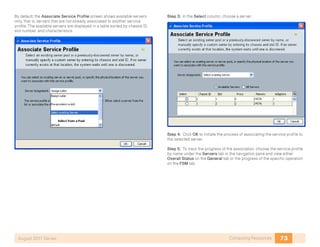
Step 1: To create VSAN 4 and add it to port FC1/4 with the name General-
Storage, enter the following from the command line:
vsan database
vsan 4 name “General-Storage”
vsan 4 interface fc1/4
Using Device Manager, select FC->VSANS.](https://image.slidesharecdn.com/presentation-datacenterdeploymentguide-150728034823-lva1-app6891/85/Presentation-data-center-deployment-guide-24-320.jpg)

![22Storage InfrastructureAugust 2011 Series
The General tab appears:
Step 2: Connect devices to the Fibre Channel ports and activate the ports.
When the initiator or target starts up, it automatically logs into the fabric.
Upon login, the initiator or target WWN is made known to the fabric. To
display this fabric login database, enter the following command through the
Cisco MDS 9000 switch CLI:
p3-mds9148-1# show flogi database
-----------------------------------------------------------------------------
INTERFACE VSAN FCID PORT NAME NODE NAME
-----------------------------------------------------------------------------
fc1/1 4 0x050000 50:06:01:60:3c:e0:60:e2 50:06:01:60:bc:e0:60:e2
fc1/3 4 0x050100 10:00:00:00:c9:92:80:1c 20:00:00:00:c9:92:80:1c
fc1/4 4 0x050200 10:00:00:00:c9:91:d5:6c 20:00:00:00:c9:91:d5:6c
fc1/5 4 0x050300 10:00:00:00:c9:8c:60:b4 20:00:00:00:c9:8c:60:b4
fc1/6 4 0x050400 10:00:00:00:c9:86:44:80 20:00:00:00:c9:86:44:80
fc1/7 4 0x050500 10:00:00:00:c9:87:be:1c 20:00:00:00:c9:87:be:1c
fc1/15 4 0x050600 20:41:00:05:9b:76:b2:80 20:04:00:05:9b:76:b2:81
fc1/16 4 0x050700 20:42:00:05:9b:76:b2:80 20:04:00:05:9b:76:b2:81
Procedure 4 Configure Device Aliases
Device aliases map the long WWNs for easier zoning and identification of
initiators and targets. An incorrect device name may cause unexpected
results. Device aliases can be used for zoning, port-security, QOS, and show
commands.
There are two ways to configure device aliases: CLI or Device Manager.
To configure device aliases using the CLI, complete the following steps:
Step 1: Apply the following configuration:
device-alias database
device-alias name emc-a0 pwwn 50:06:01:60:3c:e0:60:e2
device-alias name p3-3rd-1-hba0-a pwwn 10:00:00:00:c9:8c:60:b4
device-alias name p3-3rd-2-hba0-a pwwn 10:00:00:00:c9:86:44:80
device-alias name p3-3rd-3-hba0-a pwwn 10:00:00:00:c9:87:be:1c
device-alias name p3-c210-1-cna-a pwwn 21:00:00:c0:dd:11:28:29
device-alias name p3-dc-6100-fc-1 pwwn 20:41:00:05:9b:76:b2:80
device-alias name p3-dc-6100-fc-2 pwwn 20:42:00:05:9b:76:b2:80
device-alias name p3-c200-1-hba0-a pwwn 10:00:00:00:c9:92:80:1c
device-alias name p3-c210-1-hba0-a pwwn 10:00:00:00:c9:91:d5:6c
exit
device-alias commit
Step 2: Aliases are now visible when you enter the show flogi database
command.
p3-mds9148-1# show flogi database
-----------------------------------------------------------------------------
INTERFACE VSAN FCID PORT NAME NODE NAME
-----------------------------------------------------------------------------
fc1/1 4 0x050000 50:06:01:60:3c:e0:60:e2 50:06:01:60:bc:e0:60:e2
[emc-a0]
fc1/3 4 0x050100 10:00:00:00:c9:92:80:1c 20:00:00:00:c9:92:80:1c
[p3-c200-1-hba0-a]
fc1/4 4 0x050200 10:00:00:00:c9:91:d5:6c 20:00:00:00:c9:91:d5:6c
[p3-c210-1-hba0-a]
fc1/5 4 0x050300 10:00:00:00:c9:8c:60:b4 20:00:00:00:c9:8c:60:b4
[p3-3rd-1-hba0-a]](https://image.slidesharecdn.com/presentation-datacenterdeploymentguide-150728034823-lva1-app6891/85/Presentation-data-center-deployment-guide-26-320.jpg)
![23Storage InfrastructureAugust 2011 Series
fc1/6 4 0x050400 10:00:00:00:c9:86:44:80 20:00:00:00:c9:86:44:80
[p3-3rd-2-hba0-a]
fc1/7 4 0x050500 10:00:00:00:c9:87:be:1c 20:00:00:00:c9:87:be:1c
[p3-3rd-3-hba0-a]
fc1/15 4 0x050600 20:41:00:05:9b:76:b2:80 20:04:00:05:9b:76:b2:81
[p3-dc-6100-fc-1]
fc1/16 4 0x050700 20:42:00:05:9b:76:b2:80 20:04:00:05:9b:76:b2:81
[p3-dc-6100-fc-2]
To configure device aliases using Device Manager, complete the following
steps:
Step 3: Access the Device Alias window, FC->Advanced->Device Alias.
Step 4: Click Create.
Step 5: Enter a device alias name and paste in or type the WWN of the host.
Step 6: Click CFS->Commit when complete.
Procedure 5 Configure Zoning
• Zoning can be configured from the CLI (23) and from Fabric Manager
(24). Both will be shown.
• Leading practices for zoning:
• Configure zoning between a single initiator and a single target per zone.
• A single initiator can also be configured to multiple targets in the same
zone.
• Zone naming should follow a simple naming convention of
initiator_x_target_x.
• p3-c100-1-hba0-a_SAN-A
• p3-c210-1-hba0-a_SAN-A
• Limiting zoning to a single initiator with a single or multiple target helps
prevent disk corruption and data loss.
Option 1. To create a zone with the CLI, complete the follow-
ing steps:
Step 1: In configuration mode, enter zone name and vsan number.
zone name p3-c210-1-hba0-a-SAN-A vsan 4](https://image.slidesharecdn.com/presentation-datacenterdeploymentguide-150728034823-lva1-app6891/85/Presentation-data-center-deployment-guide-27-320.jpg)
![25Storage InfrastructureAugust 2011 Series
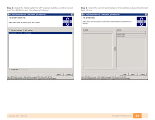
Step 5: On the left side of the zone database window are two sections,
Zonesets and Zones. Across the top, the current VSAN and switch are
displayed. The two sections on the right side list zones and zone members.
Click on Insert to create a new zone.
Step 6: Highlight the new zone. On the bottom of the right hand side of the
database window targets and initiators that have logged in the fabric for the
selected VSAN are available to be added to the new zone. Highlight initiator
or targets to add to the zone and click Add to Zone.
Step 7: Right-click Zoneset to insert a new zoneset. Drag zones just created
from the zone box to the zoneset folder just created.
Step 8: When finished, to activate the configured zoneset, click Activate in
the bottom right of the window.
Procedure 6 Troubleshoot the Configuration
Step 1: To check the fabric configuration for proper zoning, use the show
zoneset active command to display the active zoneset. Each zone that is a
member of the active zoneset is displayed with an asterisk (*) to the left of
the member. If there is not an asterisk to the left, the host is either down and
not logged into the fabric or there is a misconfiguration of the port VSAN or
zoning. Use the show zone command to display all configured zones on the
Cisco MDS 9000 Family switch.
Step 2: In a Fibre Channel fabric, each host or disk requires a Fibre Channel
ID (FC ID). When a fabric login (FLOGI) is received from the device, this ID is
assigned by the fabric. If the required device is displayed in the FLOGI table,
the fabric login is successful.
p3-mds9148-1# show zoneset active
zoneset name Zoneset1 vsan 4
zone name p3-c210-1-hba0-a-SAN-A vsan 4
* fcid 0x050200 [pwwn 10:00:00:00:c9:91:d5:6c] [p3-c210-1-
hba0-a]
* fcid 0x050000 [pwwn 50:06:01:60:3c:e0:60:e2] [emc-a0]
zone name p3-c200-1-hba0-a-SAN-A vsan 4
* fcid 0x050000 [pwwn 50:06:01:60:3c:e0:60:e2] [emc-a0]
* fcid 0x050100 [pwwn 10:00:00:00:c9:92:80:1c] [p3-c200-1-
hba0-a]](https://image.slidesharecdn.com/presentation-datacenterdeploymentguide-150728034823-lva1-app6891/85/Presentation-data-center-deployment-guide-29-320.jpg)


![34Storage InfrastructureAugust 2011 Series
Step 2: On the Cisco Nexus 5500 Series switches, display the FCoE
addresses.
dc3-5k-1# sh fcoe database
---------------------------------------------------------------------
INTERFACE FCID PORT NAME MAC ADDRESS
---------------------------------------------------------------------
vfc1 0x050b00 21:00:00:c0:dd:11:28:29 00:c0:dd:11:28:29
Step 3: The addresses appear in the current Fiber Channel login database
on the Cisco MDS 9100 Series switch. The first line below is the Cisco Nexus
5548 Series switch. The second ID is the host on the vfc 1 interface.
p3-mds9148-1# sh flogi da
------------------------------------------------------------------------
INTERFACE VSAN FCID PORT NAME NODE NAME
------------------------------------------------------------------------
port-channel 256 1 0xb41300 25:00:00:05:73:ab:27:00 20:01:00:05:73:ab:27:01
port-channel 256 4 0x050b00 21:00:00:c0:dd:11:28:29 20:00:00:c0:dd:11:28:29
Step 4: The Fiber Channel name server database differentiates the Cisco
Nexus 5548 Series switch WWN from the actual host WWN. The switch
appears as type NPV and the host as expected will show up as an initiator.
p3-mds9148-1# show fcns database
VSAN 4:
------------------------------------------------------------------------
FCID TYPE PWWN (VENDOR) FC4-TYPE:FEATURE
0x050600 N 0x050b00 N 21:00:00:c0:dd:11:28:29 (Qlogic) scsi-fcp:init
[p3-c210-1-cna-a]
Zoning and device aliases are configured as in the Fibre Channel section.
Note: Much of the configuration of the Cisco Nexus 5000 Series switch can
also be done from within Device Manager; however, Device Manager cannot
be used to configure VLANs or Ethernet Trunks on the Cisco Nexus 5000
Series switches.](https://image.slidesharecdn.com/presentation-datacenterdeploymentguide-150728034823-lva1-app6891/85/Presentation-data-center-deployment-guide-38-320.jpg)


![40Network SecurityAugust 2011 Series
Procedure 3 Configure Cisco ASA Dynamic Routing
Because the ASAs are the gateway to the secure VLANs in the server room,
the ASA pair must be configured to participate in the network’s EIGRP
updates to advertise the connected secure subnets into the LAN. This way,
the servers connected to the secure VLANs will be reachable.
Step 1: Enter the following text at the command line to configure the ASA
pair:
router eigrp 1
no auto-summary
network 10.10.53.0 255.255.255.128
network 10.10.54.0 255.255.255.0
network 10.10.55.0 255.255.255.0
passive-interface default
no passive-interface DCVLAN153
Procedure 4 Configure the ASAs for High Availability
The ASA firewalls are configured for Active-Standby High Availability.
Step 1: Define the primary firewall’s failover configuration. The two lines of
the configuration that begin with ‘failover polltime’ reduce the failover timers
from the defaults in order to achieve sub-second failover. Improved failover
times reduce application and user impact during outages. Reducing the
failover timer intervals below these values is not recommended:
failover lan unit primary
failover lan interface failover GigabitEthernet0/1
failover polltime unit msec 200 holdtime msec 800
failover polltime interface msec 500 holdtime 5
failover key [key]
failover replication http
failover link failover GigabitEthernet0/1
failover interface ip failover 10.10.53.130 255.255.255.252
standby 10.10.53.129
Step 2: Define the secondary firewall’s failover configuration. The failover
key value must match on the two devices that are configured in the active-
standby HA pair:
failover lan unit secondary
failover lan interface failover GigabitEthernet0/1
failover polltime unit msec 200 holdtime msec 800
failover polltime interface msec 500 holdtime 5
failover key [key]
failover replication http
failover link failover GigabitEthernet0/1
failover interface ip failover 10.10.53.130 255.255.255.252
standby 10.10.53.129
Step 3: Add configuration so that the active firewall will defer to the standby
firewall if connectivity is lost on the DC VLANs:
monitor-interface DCVLAN154
monitor-interface DCVLAN155
Evaluate and Deploy Security Policy
1. Evaluate Security Policy Requirements
2. Deploy the Appropriate Security Policy
Process
This section describes the steps required to evaluate which type of policy
fits an organization’s Data Center security requirements and provides the
procedures necessary to apply these policies.](https://image.slidesharecdn.com/presentation-datacenterdeploymentguide-150728034823-lva1-app6891/85/Presentation-data-center-deployment-guide-44-320.jpg)


![44Network SecurityAugust 2011 Series
The sensor’s management port is connected to the Data Center manage-
ment VLAN where the sensors can route to or directly reach the manage-
ment station.
Step 1: Gain access to the IPS SSP console through the serial console on
the IPS SSP module on the front panel of the 5585.
You can also gain access the console on the IPS SSP by using the
“session 1” command from the ASA SSP’s CLI,
Tech Tip
Step 2: Log in to the IPS device. The default username and password are
both cisco. You will be prompted to change the login password for the
“cisco” user.
Step 3: At the IPS module’s command-line interface, launch the System
Configuration Dialogue as follows:
sensor# setup
Step 4: The IPS module enters the interactive setup. Define the IPS mod-
ule’s hostname:
--- Basic Setup ---
--- System Configuration Dialog ---
At any point you may enter a question mark ‘?’ for help.
Use ctrl-c to abort configuration dialog at any prompt.
Default settings are in square brackets ‘[]’.
Current time: Mon Oct 12 23:31:38 2009
Setup Configuration last modified: Mon Oct 12 23:22:27 2009
Enter host name [sensor]: dc-ips-a
Step 5: Define the IP address and gateway address for the IPS module’s
external management port:
Enter IP interface [192.168.1.62/24,192.168.1.250]:
10.10.63.21/24,10.10.63.1
Step 6: To control management access to the IPS module , define the
access list. For the Midsize-2500 network, all addresses in the HQ subnet
(10.10.0.0/16) will be allowed. Hit “enter” at a blank prompt to go to the next
step:
Modify current access list?[no]: yes
Current access list entries:
No entries
Permit: 10.10.0.0/16
Permit:
Step 7: Accept the default answer (‘no’) to the next three questions:
Use DNS server for Global Correlation? [no]:
Use HTTP proxy server for Global Correlation? [no]:
Modify system clock settings?[no]:
Note the following:
• Global Correlation will be disabled until later in the configuration
process.
• An HTTP proxy server address will not be needed for a network that
was configured according to the SBA Borderless Network Foundation
Deployment Guide.
• You will configure time details in the sensor’s GUI console.](https://image.slidesharecdn.com/presentation-datacenterdeploymentguide-150728034823-lva1-app6891/85/Presentation-data-center-deployment-guide-48-320.jpg)
![45Network SecurityAugust 2011 Series
Step 8: Accept the default answer (‘off’) to the option to participate in the
SensorBase Network:
Participation in the SensorBase Network allows Cisco to
collect aggregated statistics about traffic sent to your IPS.
SensorBase Network Participation level? [off]:
Step 9: The IPS SSP displays your configuration and a brief menu with
four options. To save your configuration and exit the System Configuration
Dialogue, enter ‘2’:
The following configuration was entered.
[removed for brevity]
exit
[0] Go to the command prompt without saving this
configuration.
[1] Return to setup without saving this configuration.
[2] Save this configuration and exit setup.
[3] Continue to Advanced setup.
Enter your selection [3]: 2
Warning: DNS or HTTP proxy is required for global correlation
inspection and reputation filtering, but no DNS or proxy
servers are defined.
--- Configuration Saved ---
Complete the advanced setup using CLI or IDM.
To use IDM, point your web browser at https://<sensor-ip-
address>.
Step 10: Repeat steps 1-10 for the IPS sensor installed in the other ASA
chassis. Be sure to use a different IP address on the other sensor’s man-
agement interface.
Procedure 2 Completing Basic Configuration
Once the basic setup in the System Configuration Dialogue is complete,
you will use the startup wizard in the integrated management tool, Cisco
Adaptive Security Device Manager/IPS Device Manager (ASDM/IDM), to
complete the remaining tasks in order to configure a basic IDS configuration:
• Configure time settings
• Configure DNS and NTP servers
• Define a basic IDS configuration
• Configure Inspection Service Rule Policy
• Assign interfaces to virtual sensors
Step 1: Navigate to Sensor Setup > Startup Wizard, and click “Launch
Startup Wizard”:
Step 2: Review the Startup Wizard Introduction, and click ‘Next’.
Step 3: Configure the DNS server address, time zone, and NTP server
address, and then if necessary for your time zone, select ‘Enable
Summertime.’ Ensure that ‘Authenticated NTP’ is not selected, and then click
Next.](https://image.slidesharecdn.com/presentation-datacenterdeploymentguide-150728034823-lva1-app6891/85/Presentation-data-center-deployment-guide-49-320.jpg)


![56Computing ResourcesAugust 2011 Series
Completing the Initial System Setup
1. Complete Physical Setupup
2. Complete Initial Fabric Interconnect Setup
Process
Procedure 1 Complete Physical Setup
The Cisco UCS Fabric Interconnect acts as the concentration point for all
cabling to and from the UCS Blade Chassis.
Step 1: Connect the two fabric interconnects together using the integrated
ports labeled L1/L2. These ports are used for replication of cluster informa-
tion between the two fabric interconnects, not the forwarding of data traffic.
Step 2: Attach the Management Ethernet ports from each fabric intercon-
nect to a management network or appropriate Ethernet segment where they
can be accessed for overall administration of the system.
Step 3: Populate each blade chassis with two fabric extenders (I/O mod-
ules) to provide connectivity back to the fabric interconnects.
Step 4: Cable one I/O module to the first fabric interconnect. Cable the
other I/O module to the second fabric interconnect. After you have config-
ured the fabric interconnects, they will be designated as “A” and “B” fabrics.
You can connect the I/O modules to the fabric interconnects by using one,
two, or four cables per module. For system resiliency and throughput we
recommend a minimum of two connections per I/O module. Ensure that all
of the connections from a given I/O module only attach to one of the fabric
interconnects; I/O modules themselves are not “dual-homed”.
Procedure 2 Complete Initial Fabric Interconnect Setup
You can easily accomplish the initial configuration of the fabric intercon-
nects through the Basic System Configuration dialog that launches when
you power on a new or un-configured unit.
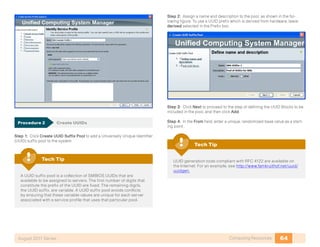
Step 1: Connect a terminal to the console port of the first system to be
configured and press Enter.
Step 2: In the Basic System Configuration Dialog that follows, enter con-
sole, setup, and yes, and then establish a password for the admin account.
---- Basic System Configuration Dialog ----
This setup utility will guide you through the basic
configuration of the system. Only minimal configuration
including IP connectivity to the Fabric interconnect and its
clustering mode is performed through these steps.
Type Ctrl-C at any time to abort configuration and reboot
system. To back track or make modifications to already entered
values, complete input till end of section and answer no when
prompted to apply configuration.
Enter the configuration method. (console/gui) ? console
Enter the setup mode; setup newly or restore from backup.
(setup/restore) ? setup
You have chosen to setup a new Fabric interconnect. Continue?
(y/n): y
Enter the password for “admin”: xxxxxxxx
Confirm the password for “admin”: xxxxxxxx
Step 3: Next you are prompted to create a new cluster or add to an existing
cluster. The Cisco UCS cluster consists of two fabric interconnects, with all
associated configuration replicated between the two for all devices in the
system. Enter yes to create a new cluster.
Do you want to create a new cluster on this Fabric
interconnect (select ‘no’ for standalone setup or if you want
this Fabric interconnect to be added to an existing cluster)?
(yes/no) [n]: yes](https://image.slidesharecdn.com/presentation-datacenterdeploymentguide-150728034823-lva1-app6891/85/Presentation-data-center-deployment-guide-60-320.jpg)
![57Computing ResourcesAugust 2011 Series
Step 4: Each fabric interconnect has a unique physical IP address. There is
also a shared cluster IP address that is used to access Cisco UCS Manager
after the system initialization is completed. The fabric interconnects are
assigned one of two unique fabric IDs for both Ethernet and Fibre Channel
networking. Choose fabric A for the first fabric interconnect that you are
setting up.
Enter the switch fabric (A/B) []: a
Step 5: The system name is shared across both fabrics, so “-a” or “-b” is
automatically appended to the name that you specify in the Basic System
Configuration Dialog when you set up one of the units.
Enter the system name: sba-ucs-10
Step 6: Apply the following example settings as you respond to the
prompts, or use setting specific to your implementation.
Physical Switch Mgmt0 IPv4 address : 10.10.63.65
Physical Switch Mgmt0 IPv4 netmask : 255.255.255.0
IPv4 address of the default gateway : 10.10.63.1
Cluster IPv4 address : 10.10.63.64
Configure the DNS Server IPv4 address? (yes/no) [n]: yes
DNS IPv4 address : 10.10.63.10
Configure the default domain name? (yes/no) [n]: yes
Default domain name : cisco.local
Step 7: The Basic System Configuration Dialog displays a summary of the
configuration options that you chose. Verify the accuracy of the settings.
Unless the settings require correction, enter “yes” to apply the configuration.
The system assumes the new identity that you configured.
Following configurations will be applied:
Switch Fabric=A
System Name=sba-ucs-10
Physical Switch Mgmt0 IP Address=10.10.63.65
Physical Switch Mgmt0 IP Netmask=255.255.255.0
Default Gateway=10.10.63.1
Cluster Enabled=yes
Cluster IP Address=10.10.63.64
Apply and save the configuration (select ‘no’ if you want to
re-enter)? (yes/no): yes
Applying configuration. Please wait.
Configuration file – Ok
Step 8: After the system is reset, you can add the second fabric intercon-
nect to the cluster. Because you have already defined the cluster, you only
need to acknowledge the prompts to add the second fabric interconnect to
the cluster and set a unique IP address.
Enter the configuration method. (console/gui) ? console
Installer has detected the presence of a peer Fabric
interconnect. This Fabric interconnect will be added to the
cluster. Continue (y/n) ? y
Enter the admin password of the peer Fabric interconnect:
Connecting to peer Fabric interconnect... done
Retrieving config from peer Fabric interconnect...done
Peer Fabric interconnect Mgmt0 IP Address: 10.10.63.65
Peer Fabric interconnect Mgmt0 IP Netmask: 255.255.255.0
Cluster IP address: 10.10.63.64
Physical Switch Mgmt0 IPv4 address : 10.10.63.66
Apply and save the configuration (select ‘no’ if you want to
re-enter)? (yes/no): yes
Applying configuration. Please wait.
Configuration file – Ok
From this point forward, the Cisco UCS Manager GUI may be used for
primary management of the system; however, you should be familiar with the
console in case you need very low-bandwidth remote access or a separate
mode of access for administrative tasks such as code upgrades or system
troubleshooting.](https://image.slidesharecdn.com/presentation-datacenterdeploymentguide-150728034823-lva1-app6891/85/Presentation-data-center-deployment-guide-61-320.jpg)


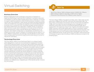


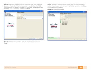
![81Virtual SwitchingAugust 2011 Series
Procedure 2 Configure the VSA
Step 1: Using an SSH client, ssh to the previously configured CIMC
address.
Step 2: Log in with the username admin and your password configured for
the CIMC.
Step 3: The prompt, ucs-c2xx# appears. Enter connect host
Step 4: The scripted VSA installation will prompt for configuration
information
CISCO Serial Over LAN:
Close Network Connection to Exit
Enter the password for “admin”:
Weak Password entered
Please enter a Strong Password.
*******************************************************
Strong Password should not be easy to decipher
Short and Easy-to-decipher passwords are not encouraged
Be sure to configure a strong password that
is at least eight characters long, contains
both upper and lower case letters, and contains numbers.
*******************************************************
Enter the password for “admin”:
Confirm the password for “admin”:
Enter HA role[primary/secondary]: primary](https://image.slidesharecdn.com/presentation-datacenterdeploymentguide-150728034823-lva1-app6891/85/Presentation-data-center-deployment-guide-85-320.jpg)
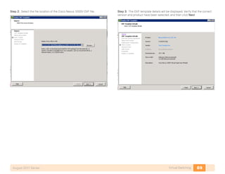
![82Virtual SwitchingAugust 2011 Series
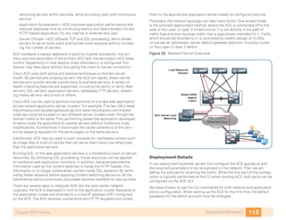
Figure 17. Nexus 1010 Physical Connectivity
The Network Uplink Type section gives several options. Given the number
of ports available to the VSA’s in this setup, network type number 4 was
chosen. Each pair of ports are connected to two separate Nexus 2248 Fabric
Extenders. Port speeds are 1 gigabit Ethernet.
Enter network-uplink type <1-4>:
1. Ports 1-2 carry all management, control and data vlans
2. Ports 1-2 management and control, ports 3-6 data
3. Ports 1-2 management, ports 3-6 control and data
4. Ports 1-2 management, ports 3-4 control, ports 5-6 data 4
Enter control vlan <1-3967, 4048-4093>: 160
Enter the domain id<1-4095>: 300
Enter management vlan <1-3967, 4048-4093>: 163
Saving boot configuration. Please wait...
[########################################] 100%
Step 5: VSA Management Configuration begins here:
---- Basic System Configuration Dialog ----
This setup utility will guide you through the basic
configuration of the system. Setup configures only enough
connectivity for management
of the system.
Press Enter at anytime to skip a dialog. Use ctrl-c at anytime
to skip the remaining dialogs.
Would you like to enter the basic configuration dialog (yes/
no): y
Create another login account (yes/no) [n]:
Configure read-only SNMP community string (yes/no) [n]:
Configure read-write SNMP community string (yes/no) [n]:
Enter the VSA name : p3-vsa-1010-1
Continue with Out-of-band (mgmt0) management configuration?
(yes/no) [y]:
Mgmt0 IPv4 address : 10.10.63.14
Mgmt0 IPv4 netmask : 255.255.255.0
Configure the default gateway? (yes/no) [y]:
IPv4 address of the default gateway : 10.10.63.1
Configure advanced IP options? (yes/no) [n]:
Enable the telnet service? (yes/no) [y]:
Enable the ssh service? (yes/no) [n]: y
Type of ssh key you would like to generate (dsa/rsa) : rsa
Number of key bits <768-2048> : 1024
Configure the ntp server? (yes/no) [n]: y
NTP server IPv4 address : 10.10.48.17
The following configuration will be applied:
switchname p3-vsa-1010-1
interface mgmt0
ip address 10.10.63.14 255.255.255.0
no shutdown
vrf context management
ip route 0.0.0.0/0 10.10.63.1
telnet server enable
ssh key rsa 1024 force
ssh server enable](https://image.slidesharecdn.com/presentation-datacenterdeploymentguide-150728034823-lva1-app6891/85/Presentation-data-center-deployment-guide-86-320.jpg)
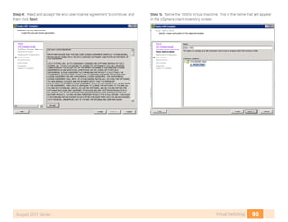
![83Virtual SwitchingAugust 2011 Series
ntp server 10.10.48.17
Would you like to edit the configuration? (yes/no) [n]:
Use this configuration and save it? (yes/no) [y]: y
[########################################] 100%
System is going to reboot to configure network uplinks
Step 6: Repeat the identical processes for the secondary VSA. Use the
same Domain ID and select HA role as secondary.
The appliance is now configured and ready for modules to be installed.
To manage the host, use an SSH client to the management address of the
primary VSA.
Procedure 3 Install the Cisco Nexus 1000V on the VSA
Step 1: Copy a Cisco Nexus 1000V ISO image from the downloaded Cisco
Nexus 1000V software package to the VSA repository. For this example, we
are using the nexus-1000V.4.0.4.SV1.3b.zip bundle from CCO. Retrieve the
.iso image from the directory Nexus-1000v.4.0.4.SV1.3b->VSM->Install. Place
this image in a location that can be reached by the file transfer protocol of
your choice. TFTP, SCP, SFTP, and FTP are available.
p3-vsa-1010-1# copy tftp: bootflash:repository/
Enter source filename: nexus-1000v.4.0.4.SV1.3b.iso
Enter vrf (If no input, current vrf ‘default’ is considered):
management
Enter hostname for the tftp server: 10.10.48.34
Trying to connect to tftp server......
Connection to Server Established.
/
TFTP get operation was successful
Step 2: Create a virtual service blade on the VSA. With the Primary and
Secondary VSA configured, the VSA automatically creates the secondary
VSM on the secondary VSA without any user intervention.
p3-vsa-1010-1# conf t
p3-vsa-1010-1(config)# virtual-service-blade vsm-1000v-1010
Step 3: Attach an ISO image to this blade. Enter the ISO image file name
previously copied to the repository.
p3-vsa-1010-1(config-vsb-config)# virtual-service-blade-type
new nexus-1000v.4.0.4.SV1.3b.iso
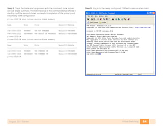
Step 4: Check the status of your current blade creation.
p3-vsa-1010-1(config-vsb-config)# show virtual-service-blade summary
--------------------------------------------------------------------
Name Role State Nexus1010-Module
-------------------------------------------------------------------
vsm-1000v-1010 PRIMARY VSB NOT PRESENT Nexus1010-PRIMARY
vsm-1000v-1010 SECONDARY VSB NOT PRESENT Nexus1010-SECONDARY
Step 5: Assign the control and packet vlans VLANS created on the VSA
previously. The management VLAN is automatically inherited from the
management VLAN configured on the VSA.
p3-vsa-1010-1(config-vsb-config)# interface control vlan 160
p3-vsa-1010-1(config-vsb-config)# interface packet vlan 159
Step 6: Enable the service blade. In the dialog that appears, configure the
management IP address for the VSM, host name, and password.
p3-vsa-1010-1(config-vsb-config)# enable
Enter vsb image: [nexus-1000v.4.0.4.SV1.3b.iso]
Enter domain id[1-4095]: 100
Management IP version [V4/V6]: [V4]
Enter Management IP address: 10.10.63.94
Enter Management subnet mask: 255.255.255.0
IPv4 address of the default gateway: 10.10.63.1
Enter HostName: vsm-1000v-1010
Enter the password for ‘admin’: c1sco123
Step 7: No shut the service blade, exit, and save the configuration for the
VSA. This will turn on the primary and secondary VSM.
p3-vsa-1010-1(config-vsb-config)# no shut
p3-vsa-1010-1(config-vsb-config)# end
p3-vsa-1010-1# copy running-configs startup-config
[########################################] 100%](https://image.slidesharecdn.com/presentation-datacenterdeploymentguide-150728034823-lva1-app6891/85/Presentation-data-center-deployment-guide-87-320.jpg)


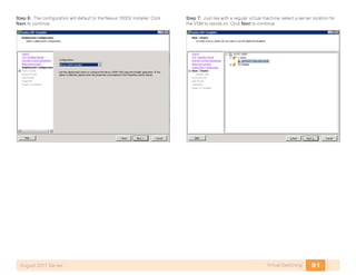


![113Application ResiliencyAugust 2011 Series
Configuring ACE
1. Add the ACE to the Network
2. Configure a Load-Balancing Policy
Process
Procedure 1 Add the ACE to the Network
Step 1: Connect a console cable to the ACE appliance to perform initial
configuration of the admin user, then exit from the initial configuration dialog
at the prompt.
switch login: admin
Password: admin
Admin user is allowed to log in only from console until the
default password is changed.
www user is allowed to log in only after the default password
is changed.
Enter the new password for user “admin”:
Confirm the new password for user “admin”:
admin user password successfully changed.
Enter the new password for user “www”:
Confirm the new password for user “www”:
www user password successfully changed.
Cisco Application Control Software (ACSW)
TAC support: http://www.cisco.com/tac
Copyright © 1985-2009 by Cisco Systems, Inc. All rights
reserved.
The copyrights to certain works contained herein are owned
by other third parties and are used and distributed under
license.
Some parts of this software are covered under the GNU Public
License. A copy of the license is available at http://www.gnu.
org/licenses/ gpl.html.
ACE>
This script will perform the configuration necessary for a
user to manage the ACE Appliance using the ACE Device Manager.
The management port is a designated Ethernet port that has
access to the same network as your management tools including
the ACE Device Manager.
You will be prompted for the Port Number, IP Address, Netmask,
and Default Route (optional).
Enter ‘ctrl-c’ at any time to quit the script
ACE>Would you like to enter the basic configuration dialog
(yes/no) [y]: n
switch/Admin#
Step 2: Before proceeding with any additional configuration, set up the
basic network security policies to allow for management access into the
ACE.
access-list ALL line 8 extended permit ip any any
class-map type management match-any remote_access
2 match protocol xml-https any
3 match protocol icmp any
4 match protocol telnet any
5 match protocol ssh any
6 match protocol http any
7 match protocol https any
8 match protocol snmp any
policy-map type management first-match remote_mgmt_allow_
policy
class remote_access
permit](https://image.slidesharecdn.com/presentation-datacenterdeploymentguide-150728034823-lva1-app6891/85/Presentation-data-center-deployment-guide-117-320.jpg)


Presentation data center deployment guide
- 1. Data Center Deployment Guide August 2011 Series
- 2. PrefaceAugust 2011 Series Preface This guide is a Cisco® Smart Business Architecture (SBA) guide. Who Should Read This Guide This guide is written for people who fill a variety of roles: • Systems engineers who need standard procedures for implementing solutions • Project managers who need reference material for creating statements of work for SBA implementations • Sales partners who want help with selling new technology or who create their own implementation documentation • Trainers who need material for classroom instruction or on-the-job training In general, you can also use SBA guides to improve consistency among engineers, among deployments, and to improve scoping and costing of deployment jobs. Release Series Cisco updates and enhances SBA guides twice a year. Before we release a series of SBA guides, we test them together in the SBA lab, as a complete system. To ensure the mutual compatibility of designs in SBA guides, you should use guides that belong to the same SBA series. All SBA guides include the series name on the cover and at the bottom left of each page. The series are named as follows: • February year Series • August year Series where year indicates the calendar year of the series. You can find the most recent series of SBA guides at the following sites: Customer access: http://www.cisco.com/go/sba Partner access: http://www.cisco.com/go/sbachannel How to Read Commands Many SBA guides provide specific details about how to configure Cisco net- work devices that run Cisco IOS, Cisco NX-OS, or other operating systems that you configure at a command-line interface (CLI). This section describes the conventions used to specify commands that you must enter. Commands to enter at a CLI appear as follows: configure terminal Commands that specify a value for a variable appear as follows: ntp server 10.10.48.17 Commands with variables that you must define appear as follows: class-map [highest class name] Commands shown in an interactive example, such as a script or when the command prompt is included, appear as follows: Router# enable Long commands that line wrap are underlined. Enter them as one command: wrr-queue random-detect max-threshold 1 100 100 100 100 100 100 100 100 Comments and Questions If you would like to comment on a guide or ask questions, please use the forum at the bottom of one of the following sites: Customer access: http://www.cisco.com/go/sba Partner access: http://www.cisco.com/go/sbachannel An RSS feed is available if you would like to be notified when new comments are posted.
- 3. Table of Contents Table of ContentsAugust 2011 Series What’s In This SBA Guide. . . . . . . . . . . . . . . . . . . . . . . . . . . . . . . . . . . . . . . . . . . . . . . . . . 1 About SBA. . . . . . . . . . . . . . . . . . . . . . . . . . . . . . . . . . . . . . . . . . . . . . . . . . . . . . . . . . . . . . . 1 About This Guide. . . . . . . . . . . . . . . . . . . . . . . . . . . . . . . . . . . . . . . . . . . . . . . . . . . . . . . . 1 Introduction. . . . . . . . . . . . . . . . . . . . . . . . . . . . . . . . . . . . . . . . . . . . . . . . . . . . . . . . . . . . . . . . 2 Supporting Rapid Application Growth . . . . . . . . . . . . . . . . . . . . . . . . . . . . . . . . . . . 2 Managing Growing Data Storage Requirements. . . . . . . . . . . . . . . . . . . . . . . . . 2 Optimizing the Investment in Server Processing Resources. . . . . . . . . . . . . 2 Securing the Organizations Critical Data . . . . . . . . . . . . . . . . . . . . . . . . . . . . . . . . 3 Architecture Overview. . . . . . . . . . . . . . . . . . . . . . . . . . . . . . . . . . . . . . . . . . . . . . . . . . . . . 4 Physical Environment. . . . . . . . . . . . . . . . . . . . . . . . . . . . . . . . . . . . . . . . . . . . . . . . . . . . . . 6 Business Overview. . . . . . . . . . . . . . . . . . . . . . . . . . . . . . . . . . . . . . . . . . . . . . . . . . . . . . . 6 Power. . . . . . . . . . . . . . . . . . . . . . . . . . . . . . . . . . . . . . . . . . . . . . . . . . . . . . . . . . . . . . . . . . . . 6 Cooling. . . . . . . . . . . . . . . . . . . . . . . . . . . . . . . . . . . . . . . . . . . . . . . . . . . . . . . . . . . . . . . . . . 6 Equipment Racking. . . . . . . . . . . . . . . . . . . . . . . . . . . . . . . . . . . . . . . . . . . . . . . . . . . . . . 6 Summary. . . . . . . . . . . . . . . . . . . . . . . . . . . . . . . . . . . . . . . . . . . . . . . . . . . . . . . . . . . . . . . . 6 Ethernet Infrastructure. . . . . . . . . . . . . . . . . . . . . . . . . . . . . . . . . . . . . . . . . . . . . . . . . . . . . 7 Business Overview. . . . . . . . . . . . . . . . . . . . . . . . . . . . . . . . . . . . . . . . . . . . . . . . . . . . . . . 7 Technology Overview. . . . . . . . . . . . . . . . . . . . . . . . . . . . . . . . . . . . . . . . . . . . . . . . . . . . 7 Virtual Port Channel. . . . . . . . . . . . . . . . . . . . . . . . . . . . . . . . . . . . . . . . . . . . . . . . . . . . . 7 Ethernet Fabric Extension. . . . . . . . . . . . . . . . . . . . . . . . . . . . . . . . . . . . . . . . . . . . . . . . 7 Deployment Details. . . . . . . . . . . . . . . . . . . . . . . . . . . . . . . . . . . . . . . . . . . . . . . . . . . . . . 8 Initial Setup. . . . . . . . . . . . . . . . . . . . . . . . . . . . . . . . . . . . . . . . . . . . . . . . . . . . . . . . . . . . . . 9 Configure Inter-Device Links. . . . . . . . . . . . . . . . . . . . . . . . . . . . . . . . . . . . . . . . . . . 11 Summary. . . . . . . . . . . . . . . . . . . . . . . . . . . . . . . . . . . . . . . . . . . . . . . . . . . . . . . . . . . . . . 15 Storage Infrastructure. . . . . . . . . . . . . . . . . . . . . . . . . . . . . . . . . . . . . . . . . . . . . . . . . . . . 16 Business Overview . . . . . . . . . . . . . . . . . . . . . . . . . . . . . . . . . . . . . . . . . . . . . . . . . . . . 16 Technology Overview . . . . . . . . . . . . . . . . . . . . . . . . . . . . . . . . . . . . . . . . . . . . . . . . . 16 Storage Array Tested . . . . . . . . . . . . . . . . . . . . . . . . . . . . . . . . . . . . . . . . . . . . . . . . . . 18 Deployment Details. . . . . . . . . . . . . . . . . . . . . . . . . . . . . . . . . . . . . . . . . . . . . . . . . . . . 18 Configuring the Cisco MDS 9148 Switch. . . . . . . . . . . . . . . . . . . . . . . . . . . . . . . 18 Configuring Cisco UCS Rack Mount Servers for FCoE. . . . . . . . . . . . . . . . . 26 Nexus 5000 configuration for FCoE. . . . . . . . . . . . . . . . . . . . . . . . . . . . . . . . . . . . 29 Network Security. . . . . . . . . . . . . . . . . . . . . . . . . . . . . . . . . . . . . . . . . . . . . . . . . . . . . . . . . 35 Business Overview. . . . . . . . . . . . . . . . . . . . . . . . . . . . . . . . . . . . . . . . . . . . . . . . . . . . . 35 Technology Overview. . . . . . . . . . . . . . . . . . . . . . . . . . . . . . . . . . . . . . . . . . . . . . . . . . 35 Security Policy Development . . . . . . . . . . . . . . . . . . . . . . . . . . . . . . . . . . . . . . . . . . 36 Deployment Details. . . . . . . . . . . . . . . . . . . . . . . . . . . . . . . . . . . . . . . . . . . . . . . . . . . . 38 Configure Cisco ASA Firewall Connectivity. . . . . . . . . . . . . . . . . . . . . . . . . . . . 38 Evaluate and Deploy Security Policy. . . . . . . . . . . . . . . . . . . . . . . . . . . . . . . . . . . 40 Deploying Cisco Intrusion Protection System (IPS) . . . . . . . . . . . . . . . . . . . . 43 Computing Resources. . . . . . . . . . . . . . . . . . . . . . . . . . . . . . . . . . . . . . . . . . . . . . . . . . . . 53 Business Overview. . . . . . . . . . . . . . . . . . . . . . . . . . . . . . . . . . . . . . . . . . . . . . . . . . . . . 53 Technology Overview. . . . . . . . . . . . . . . . . . . . . . . . . . . . . . . . . . . . . . . . . . . . . . . . . . 53 Cisco UCS Blade Chassis System Components. . . . . . . . . . . . . . . . . . . . . . . 54 Cisco UCS Manager. . . . . . . . . . . . . . . . . . . . . . . . . . . . . . . . . . . . . . . . . . . . . . . . . . . 54 Cisco UCS C-Series Rack Servers. . . . . . . . . . . . . . . . . . . . . . . . . . . . . . . . . . . . . 55 UCS System Network Connectivity. . . . . . . . . . . . . . . . . . . . . . . . . . . . . . . . . . . . 55 Deployment Details. . . . . . . . . . . . . . . . . . . . . . . . . . . . . . . . . . . . . . . . . . . . . . . . . . . . 55 Completing the Initial System Setup. . . . . . . . . . . . . . . . . . . . . . . . . . . . . . . . . . . 56 Getting Started with UCS Manager. . . . . . . . . . . . . . . . . . . . . . . . . . . . . . . . . . . . 58 Creating an Initial Service Profile for Local Boot . . . . . . . . . . . . . . . . . . . . . . . 63 Applying Service Profiles to Physical Servers. . . . . . . . . . . . . . . . . . . . . . . . . . 72 Summary. . . . . . . . . . . . . . . . . . . . . . . . . . . . . . . . . . . . . . . . . . . . . . . . . . . . . . . . . . . . . . 75 Table of Contents
- 4. Table of ContentsAugust 2011 Series ALL DESIGNS, SPECIFICATIONS, STATEMENTS, INFORMATION, AND RECOMMENDATIONS (COLLECTIVELY, “DESIGNS”) IN THIS MANUAL ARE PRESENTED “AS IS,” WITH ALL FAULTS. CISCO AND ITS SUPPLIERS DISCLAIM ALL WARRANTIES, INCLUDING, WITHOUT LIMITATION, THE WARRANTY OF MERCHANTABILITY, FITNESS FOR A PARTICULAR PURPOSE AND NONINFRINGEMENT OR ARISING FROM A COURSE OF DEALING, USAGE, OR TRADE PRACTICE. IN NO EVENT SHALL CISCO OR ITS SUPPLIERS BE LIABLE FOR ANY INDIRECT, SPECIAL, CONSEQUENTIAL, OR INCIDENTAL DAMAGES, INCLUDING, WITHOUT LIMITA- TION, LOST PROFITS OR LOSS OR DAMAGE TO DATA ARISING OUT OF THE USE OR INABILITY TO USE THE DESIGNS, EVEN IF CISCO OR ITS SUPPLIERS HAVE BEEN ADVISED OF THE POSSIBILITY OF SUCH DAMAGES. THE DESIGNS ARE SUBJECT TO CHANGE WITHOUT NOTICE. USERS ARE SOLELY RESPONSIBLE FOR THEIR APPLICATION OF THE DESIGNS. THE DESIGNS DO NOT CONSTITUTE THE TECHNICAL OR OTHER PROFESSIONAL ADVICE OF CISCO, ITS SUPPLIERS OR PARTNERS. USERS SHOULD CONSULT THEIR OWN TECHNICAL ADVISORS BEFORE IMPLEMENTING THE DESIGNS. RESULTS MAY VARY DEPENDING ON FACTORS NOT TESTED BY CISCO. Any Internet Protocol (IP) addresses used in this document are not intended to be actual addresses. Any examples, command display output, and figures included in the document are shown for illustrative purposes only. Any use of actual IP addresses in illustrative content is unintentional and coincidental. © 2011 Cisco Systems, Inc. All rights reserved. Virtual Switching. . . . . . . . . . . . . . . . . . . . . . . . . . . . . . . . . . . . . . . . . . . . . . . . . . . . . . . . . . 76 Business Overview. . . . . . . . . . . . . . . . . . . . . . . . . . . . . . . . . . . . . . . . . . . . . . . . . . . . . 76 Technology Overview. . . . . . . . . . . . . . . . . . . . . . . . . . . . . . . . . . . . . . . . . . . . . . . . . . 76 Nexus 1000V VEM. . . . . . . . . . . . . . . . . . . . . . . . . . . . . . . . . . . . . . . . . . . . . . . . . . . . . 77 Virtual Supervisor Module. . . . . . . . . . . . . . . . . . . . . . . . . . . . . . . . . . . . . . . . . . . . . 77 Nexus 1000V Port Profiles. . . . . . . . . . . . . . . . . . . . . . . . . . . . . . . . . . . . . . . . . . . . . 78 Nexus 1010 Virtual Services Appliance. . . . . . . . . . . . . . . . . . . . . . . . . . . . . . . . 78 Deployment Details. . . . . . . . . . . . . . . . . . . . . . . . . . . . . . . . . . . . . . . . . . . . . . . . . . . . 78 Install and Set Up the Nexus 1010. . . . . . . . . . . . . . . . . . . . . . . . . . . . . . . . . . . . . . 78 Deploying the Nexus 1000V on a ESXi host as a virtual machine. . . . . . . 88 Configure Virtualized Hosts to Use the Nexus 1000v. . . . . . . . . . . . . . . . . 100 Summary. . . . . . . . . . . . . . . . . . . . . . . . . . . . . . . . . . . . . . . . . . . . . . . . . . . . . . . . . . . . . 110 Application Resiliency. . . . . . . . . . . . . . . . . . . . . . . . . . . . . . . . . . . . . . . . . . . . . . . . . . . 111 Business Overview. . . . . . . . . . . . . . . . . . . . . . . . . . . . . . . . . . . . . . . . . . . . . . . . . . . . 111 Inflexible Application Infrastructure . . . . . . . . . . . . . . . . . . . . . . . . . . . . . . . . . . 111 Server Availability and Load . . . . . . . . . . . . . . . . . . . . . . . . . . . . . . . . . . . . . . . . . . 111 Application Security and Compliance . . . . . . . . . . . . . . . . . . . . . . . . . . . . . . . . 111 Technology Overview. . . . . . . . . . . . . . . . . . . . . . . . . . . . . . . . . . . . . . . . . . . . . . . . . 111 Deployment Details. . . . . . . . . . . . . . . . . . . . . . . . . . . . . . . . . . . . . . . . . . . . . . . . . . . 112 Configuring ACE. . . . . . . . . . . . . . . . . . . . . . . . . . . . . . . . . . . . . . . . . . . . . . . . . . . . . . 113 Summary . . . . . . . . . . . . . . . . . . . . . . . . . . . . . . . . . . . . . . . . . . . . . . . . . . . . . . . . . . . . . 115 Appendix A: Product List. . . . . . . . . . . . . . . . . . . . . . . . . . . . . . . . . . . . . . . . . . . . . . . . 116
- 5. What’s In This SBA Guide About SBA Cisco SBA helps you design and quickly deploy a full-service business network. A Cisco SBA deployment is prescriptive, out-of-the-box, scalable, and flexible. Cisco SBA incorporates LAN, WAN, wireless, security, data center, application optimization, and unified communication technologies—tested together as a complete system. This component-level approach simplifies system integration of multiple technologies, allowing you to select solutions that solve your organization’s problems—without worrying about the technical complexity. About This Guide This guide is a foundation deployment guide that is organized in modules. Each module in this guide includes the following sections: • Business Overview—Describes the business use case for the solution presented in the module. Business decision makers may find this section especially useful. • Technology Overview—Describes the technical solution for the business use case, including an introduction to the Cisco products that make up the solution. Technical decision makers can use this section to understand how the solution works. • Deployment Details—Provides step-by-step instructions for deploying and configuring the portion of the foundation that the module addresses. Systems engineers can use this section to get the solution up and running quickly and reliably. A foundation deployment guide always follows a foundation design overview on the Route to Success, shown below. 1What’s In This SBA GuideAugust 2011 Series Route to Success To ensure your success when implementing the designs in this guide, you should read any guides that this guide depends upon—shown to the left of this guide on the route above. Any guides that depend upon this guide are shown to the right of this guide. For customer access to all SBA guides: http://www.cisco.com/go/sba For partner access: http://www.cisco.com/go/sbachannel Data Center Design Overview Data Center Deployment Guide Additional Deployment Guides DC You are Here Dependent GuidesPrerequisite Guides
- 6. 2IntroductionAugust 2011 Series Introduction Midsize organizations encounter many challenges as they work to scale their information-processing capacity to keep up with demand. In a new organization, a small group of server resources may be sufficient to provide necessary applications such as file sharing, e-mail, database applications, and web services. Over time, demand for increased processing capacity, storage capacity, and distinct operational control over specific servers can cause a growth explosion commonly known as “server sprawl”. A midsize organization can then use some of the same data center technologies that larger organizations use to meet expanding business requirements in a way that keeps capital and operational expenses in check. This deployment guide provides reference architecture to facilitate rapid adoption of these data center technologies by using a common, best-practices configuration. The Cisco SBA Data Center for Midsize Organizations architecture provides an evolution from the basic “server room” infrastructure illustrated in the SBA Midsize Foundation Deployment Guide. The Data Center for Midsize Organizations is designed to address four primary business challenges: • Supporting rapid application growth • Managing growing data storage requirements • Optimizing the investment in server processing resources • Securing the organizations’ critical data Supporting Rapid Application Growth As applications scales to support a larger number of users, or new applica- tions are deployed, the number of servers required to meet the needs of the organization often increases. The first phase of the server room evolution is often triggered when the organization outgrows the capacity of the existing server room network. Many factors can limit the capacity of the existing facility, including rack space, power, cooling, switching throughput, or basic network port count to attach new servers. The architecture outlined in this guide is designed to allow the organization to smoothly scale the size of the server environment and network topology as business requirements grow. Managing Growing Data Storage Requirements As application requirements grow, the need for additional data storage capacity also increases. This can initially cause issues when storage requirements for a given server increase beyond the physical capacity of the server hardware platform in use. As the organization grows, the invest- ment in additional storage capacity is most efficiently managed by moving to a centralized storage model. A centralized storage system can provide disk capacity across multiple applications and servers providing greater scalability and flexibility in storage provisioning. A dedicated storage system provides multiple benefits beyond raw disk capacity. Centralized storage systems can increase the reliability of disk storage, which improves application availability. Storage systems allow increased capacity to be provided to a given server over the network without needing to physically attach new devices to the server itself. More sophisti- cated backup and data replication technologies are available in centralized storage systems, which helps protect the organization against data loss and application outages. Optimizing the Investment in Server Processing Re- sources As a midsize organization grows, physical servers are often dedicated to sin- gle applications to increase stability and simplify troubleshooting. However, these servers do not operate at high levels of processor utilization for much of the day. Underutilized processing resources represent an investment by the organization that is not being leveraged to its full potential. Server virtualization technologies allow a single physical server to run multiple virtual instances of a “guest” operating system, creating virtual machines (VMs). Running multiple VMs on server hardware helps to more fully utilize the organization’s investment in processing capacity, while still allowing each VM to be viewed independently from a security, configuration, and troubleshooting perspective. Server virtualization and centralized storage technologies complement one another, allowing rapid deployment of new servers and reduced downtime in the event of server hardware failures. Virtual machines can be stored completely on the centralized storage system, which decouples the identity of the VM from any single physical server. This allows the organization great flexibility when rolling out new applications or upgrading server hardware. The architecture defined in this guide is designed to facilitate easy deploy- ment of server virtualization, while still providing support for the existing installed base of equipment.
- 7. 3IntroductionAugust 2011 Series Securing the Organizations Critical Data With communication and commerce in the world becoming increasingly Internet-based, network security quickly becomes a primary concern of a growing organization. Often organizations will begin by securing their Internet edge connection, considering the internal network a trusted entity. However, an Internet firewall is only one component of building security into the network infrastructure. Frequently, threats to an organization’s data may come from within the inter- nal network. This may come in the form of on-site vendors, contaminated employee laptops, or existing servers that have already become compro- mised and may be used as a platform to launch further attacks. With the centralized repository of the organizations most critical data typically being the data center, security is no longer considered an optional component of a complete data center architecture plan. The SBA Midsize Data Center Architecture illustrates how to cleanly integrate network security capabilities such as firewall and intrusion preven- tion, protecting areas of the network housing critical server and storage resources. The architecture provides the flexibility to secure specific portions of the data center or insert firewall capability between tiers of a multi-tier application according to the security policy agreed upon by the organization.
- 8. 4Architecture OverviewAugust 2011 Series Architecture Overview The SBA Midsize Data Center Architecture is designed to allow organizations to take an existing server room environment to the next level of performance, flexibility, and security. Figure 1 provides a high-level overview of this architecture. Figure 1. SBA Midsize Data Center Architecture
- 9. 5Architecture OverviewAugust 2011 Series The SBA Midsize Data Center Architecture is designed to connect to one of the SBA Layer-3 Ethernet core solutions, as documented in the SBA Midsize Foundation Deployment Guide. The following technology areas are included within this reference architecture: • Ethernet Infrastructure—Resilient Layer-2 Ethernet networking to sup- port 10 Gigabit and 1 Gigabit Ethernet connectivity. • Storage Networking—Take advantage of IP-based storage access, Fibre Channel over Ethernet, or a full Fibre Channel SAN solution depending on your requirements. • Network Security—Integrate firewall and intrusion prevention services into the data center to protect critical application data. • Computing Resources—Leverage powerful computing platforms in both blade server and rack mount formats. • Virtual Switching—Deploy a centrally managed distributed virtual switching system for your VMware environment. • Application Resiliency—Server load balancing solutions providing high availability, scalability and security for your key applications. This architecture is designed to allow a midsize organization to position its network for growth while controlling both equipment costs and operational costs. The deployment processes documented in this guide provide concise step-by-step instructions for completing basic configuration of the components of the architecture. This approach allows you to take advantage of some of the newer technologies being used in the data centers of very large organizations without encountering a steep learning curve for the IT staff. Although this architecture has been designed and validated as a whole, the modular nature of this guide allows you to perform a gradual migration by choosing specific elements of the architecture to implement first. The remaining sections of this guide detail the various technologies that comprise this architecture.
- 10. 6Physical EnvironmentAugust 2011 Series Physical Environment Business Overview When building or changing a network, you have to carefully consider the location where you will install the equipment. When building a server room, a switch closet, or even a midsize data center, take three things into con- sideration: power, cooling, and racking. Know your options in each of these categories, and you will minimize surprises and moving of equipment later on. Power Know what equipment will be installed in the area. You cannot plan electrical work if you do not know what equipment is going to be used. Some equip- ment requires standard 110v outlets that may already be available. Other equipment can require great power needs. Does the power need to be on all the time? In most cases this answer will be yes if there are servers and storage involved. Applications don’t react very well when the power goes out, so to prevent this a uninterruptable power supply (UPS) is needed. The UPS will switch over the current load to a set of internal or external batteries. Some UPSs are online, which means the power is filtered through the batteries all the time; others are switchable, meaning they use batteries only during power losses. UPSs vary by how much load they can carry and for how long. Careful planning is required to make sure the correct UPS is purchased, installed, and managed correctly. Most UPSs provide for remote monitoring and the ability to trigger a graceful server shutdown for critical servers if the UPS is going to run out of battery. Distributing the power to the equipment can change the power require- ments as well. There are many options available to distribute the power from the outlet or UPS to the equipment. One example would be using a power strip that resides vertically in a cabinet that usually has an L6-30 input and then C13/C19 outlets with the output voltage in the 200-240 range. These strips should be at a minimum metered so one does not overload the cir- cuits. The meter provides a current reading of the load on the circuit. This is critical as a circuit breaker tripping due to being overloaded will bring down everything plugged into it with no warning causing business downtime and possible data loss. For complete remote control, power strips are available with full remote control of each individual outlet from a web browser. These vertical strips also assist in proper cable management of the power cords. Short C13/C14 and C19/C20 power cords can be used instead of much longer cords to multiple 110 volt outlets or multiple 110volt power strips. Cooling With power comes the inevitable conversion of power into heat. Without going into great detail, power in equals heat out. Planning for cooling of one or two servers and a switch with standard building air may work. Multiple servers and blade servers (along with storage, switches, etc.) need more than building air for proper cooling. Be sure to at least plan with your facili- ties team what the options are for current and future cooling. Many options are available, in-row cooling, overhead cooling, raised floor with underfloor cooling, and wall mounted cooling. Equipment Racking Where to put the equipment is a very important detail not to overlook. Proper placement and planning allow for easy growth. With the power and cooling properly evaluated racking or cabinets need to be installed. Most servers are fairly deep and, with network connections and power connections, take up even more space. Most servers will fit in a 42-inch deep cabinet, and deeper cabinets give more flexibility for cable and power management within the cabinet. Be aware of what rails are required by your servers. Most servers now come with rack mounts that use the square-hole style vertical cabinet rails. Not having the proper rails can mean having to use adapters or shelves and making management of servers and equipment difficult if not sometimes impossible without removing other equipment or sacrificing space. Data center racks should use the square rail mounting options in the cabinets. Cage nuts can be used to provide threaded mounts for such things as routers, switches, shelves, etc. that may be needed. Summary The physical environmental requirements for a data center require careful planning to provide for efficient use of space, scalability, and ease of opera- tional maintenance. Working towards deployment of the Smart Business Architecture allows you to plan the physical space for your data center with a vision towards the equipment you will be installing over time, even if you begin with a smaller scale. For additional information on data center power, cooling and equipment racking, contact Cisco partners in the area of data center environmental products such as Panduit and APC.
- 11. 7Ethernet InfrastructureAugust 2011 Series Ethernet Infrastructure Business Overview As your midsize organization grows, you may outgrow the capacity of the basic “server-room” Ethernet switching stack illustrated in the SBA Midsize Foundation Architecture. It is important to be prepared for the ongoing transition of available server hardware from 1 gigabit Ethernet attachment to 10 gigabit. Multi-tier applications often divide browser-based client services, business logic, and database layers into multiple servers, increasing the amount of server-to-server traffic and driving performance requirements higher. As the physical environment housing the organization’s servers grows to multiple racks, it also becomes more challenging to elegantly manage the cabling required to attach servers to the network. 10 Gigabit Ethernet connections help to improve overall network performance, while reducing the number of physical links required to provide the bandwidth. Technology Overview The foundation of the Ethernet network in the SBA Midsize Data Center Architecture is a resilient pair of Cisco Nexus 5000 Series switches. These switches offer the ideal platform for building a scalable, high-performance data center supporting both 10 gigabit and 1 gigabit Ethernet attached serv- ers. Optional Fibre Channel modules are available to allow integration with a Fibre-Channel based Storage Area Network (SAN). The Cisco Nexus 5000 Series also supports the Cisco Nexus 2000 Series Fabric Extenders. Fabric Extenders allow the switching fabric of the resilient switching pair to be physically extended to provide port aggregation in the top of multiple racks, reducing cable management issues as the server environment expands. The Fabric Extenders are all managed centrally from the Cisco Nexus 5000 Series switch pair, where they appear as “remote linecards” to the primary data center switches. This centralized management provides easy port provisioning and keeps operational costs down for the growing organization. The SBA Midsize Data Center Architecture leverages many advanced features of the Cisco Nexus 5000 Series switch family to provide a central switching fabric for the data center environment that is easy to deploy. This section provides an overview of the key features used in this topology and illustrates the specific physical connectivity that applies to the example configurations provided in the deployment section. Virtual Port Channel The Cisco Nexus 5000 Series switch pair providing the central Ethernet switching fabric for the SBA Midsize Data Center Architecture is configured using the Virtual Port Channel (vPC) feature. This capability allows the two switches to be used to build resilient, loop-free topologies that forward on all connected links instead of requiring Spanning Tree Protocol (STP) blocking for loop prevention. This feature enhances ease-of-use and simpli- fies configuration for the data center-switching environment. Neighboring devices such as the SBA Midsize core switches can leverage a Port Channel configuration, which bundles multiple links into a single logical link, with all available physical bandwidth being used to forward traffic. Allowing all links to forward traffic instead of requiring spanning tree to block the parallel paths for loop prevention provides greater bandwidth capacity to increase application performance. Ethernet Fabric Extension The Cisco Nexus 2000 Series Fabric Extender (FEX) delivers cost-effective and highly scalable 1 gigabit and 10 gigabit Ethernet environments. Fabric extension allows you to aggregate a group of physical switch ports at the top of each server rack, without needing to manage these ports as a separate logical switch. You can provide network resiliency by dual-homing servers into two separate fabric extenders, each of which is single homed to one member of the Cisco Nexus 5000 Series switch pair. To provide high avail- ability for servers that only support single-homed network attachment, the FEX itself may instead be dual-homed into the two members of the central switch pair. Our reference architecture example shown in Figure 2. illustrates single- homed and dual-homed FEX configurations. Each FEX includes dedicated fabric uplink ports that are designed to connect to upstream Cisco Nexus 5000 Series switches for data communication and management; these are shown as ports F1 and F2 in the illustration. The port designations on the Cisco Nexus 5000 side reflect the example ports used for reference con- figurations contained in this guide; any 10 gigabit Ethernet port on the Cisco Nexus 5000 switch may be used for FEX connection.
- 12. 8Ethernet InfrastructureAugust 2011 Series The first 8 ports of a Cisco Nexus 5010 and the first 16 ports of a Cisco Nexus 5020 switch may be configured at either 10 Gigabit or 1 Gigabit Ethernet speeds. If you have requirements for 1 Gigabit Ethernet connections directly to the switch, ensure that you are reserving the correct ports and apply the speed com- mand to control this setting. As of NX-OS 5.0(2)N1(1), all Ethernet ports of the Nexus 5548 switch support 10 Gigabit Ethernet connection speed. If 1-Gigabit Ethernet connections are required, fabric extender ports on Nexus 2148 or 2248 may be used. 10-Gigabit Ethernet connections will be supported directly to the Nexus 5548 in a future software release. Tech Tip Figure 2. Ethernet Switching Fabric Physical Connections Deployment Details The following configuration procedures are required to configure the Ethernet switching fabric for the SBA Midsize Data Center Architecture. • Establish physical connectivity • Perform Initial device configuration • Complete vPC configuration • Create port channel to SBA core • Configure fabric extender connections
- 13. 9Ethernet InfrastructureAugust 2011 Series Initial Setup 1. Establish Physical Connectivity 2. Perform Initial Device Configuration Process Procedure 1 Establish Physical Connectivity Complete the physical connectivity of the Cisco Nexus 5000 Series switch pair according to the illustration in Figure 2. (or according to the specific requirements of your implementation). Step 1: Connect ports Ethernet 1/17 and 1/18 or other available Ethernet ports between the two Cisco Nexus 5000 Series switches. This link will be used as the vPC peer-link, which allows the peer connection to form and supports forwarding of traffic between the switches if necessary during a partial link failure of one of the vPC port channels. Step 2: Connect the Management 0 ports to the SBA core switch pair (or an alternate location where they can be connected to the data center manage- ment VLAN). In our example configurations, the data center management VLAN is 163. Step 3: Connect ports Ethernet 1/19 and 1/20 or other available Ethernet ports on each Cisco Nexus 5000 Series switch to the SBA core to build the port channel which will carry production data traffic. Four 10 gigabit Ethernet connections will provide an aggregate throughput of 40 Gbps to carry data back and forth to client machines, or to be Layer-3 switched between serv- ers by the SBA core if required. Step 4: To support a dual-homed FEX with single-homed servers, connect fabric uplink ports 1 and 2 on the FEX to port Ethernet 1/13 or other available Ethernet ports, one on each Cisco Nexus 5000 Series switch. These ports will operate as a port channel to support the dual-homed FEX configuration. Step 5: Support single-homed FEX attachment by connecting fabric uplink ports 1 and 2 on each FEX to ports Ethernet 1/15 and 1/16 or other available Ethernet ports on only one member of the Cisco Nexus 5000 Series switch pair. These ports will be a port-channel, but will not be configured as a vPC port-channel, because they have physical ports connected to only one member of the switch pair. Procedure 2 Perform Initial Device Configuration Step 1: Connect a terminal cable to the console port of the first Cisco Nexus 5000 Series switch, and power on the system to enter the initial configuration dialog. Step 2: Follow the Basic System Configuration Dialog for initial device configuration of the first Cisco Nexus 5000 Series switch, as shown in the terminal capture below: Do you want to enforce secure password standard (yes/no): y Enter the password for “admin”: Confirm the password for “admin”: ---- Basic System Configuration Dialog ---- This setup utility will guide you through the basic configuration of the system. Setup configures only enough connectivity for management of the system. Please register Cisco Nexus 5000 Family devices promptly with your supplier. Failure to register may affect response times for initial service calls. Nexus devices must be registered to receive entitled support services. Press Enter at anytime to skip a dialog. Use ctrl-c at anytime to skip the remaining dialogs. Would you like to enter the basic configuration dialog (yes/ no): y Create another login account (yes/no) [n]: n Configure read-only SNMP community string (yes/no) [n]: n Configure read-write SNMP community string (yes/no) [n]: n Enter the switch name : dc3-5k-1 Continue with Out-of-band (mgmt0) management configuration? (yes/no) [y]: y
- 14. 10Ethernet InfrastructureAugust 2011 Series Mgmt0 IPv4 address : 10.10.63.10 Mgmt0 IPv4 netmask : 255.255.255.0 Configure the default gateway? (yes/no) [y]: y IPv4 address of the default gateway : 10.10.63.1 Enable the telnet service? (yes/no) [n]: y Enable the http-server? (yes/no) [y]: y Enable the ssh service? (yes/no) [y]: y Type of ssh key you would like to generate (dsa/rsa) : rsa Number of key bits <768-2048> : 2048 Configure the ntp server? (yes/no) [n]: y NTP server IPv4 address : 10.10.48.17 Enter basic FC configurations (yes/no) [n]: n The following configuration will be applied: switchname dc2-5k-1 interface mgmt0 ip address 10.10.63.10 255.255.255.0 no shutdown exit vrf context management ip route 0.0.0.0/0 10.10.63.1 exit telnet server enable feature http-server ssh key rsa 768 force ssh server enable ntp server 10.10.48.17 use-vrf management Would you like to edit the configuration? (yes/no) [n]: n Use this configuration and save it? (yes/no) [y]: y [########################################] 100% Nexus 5000 Switch dc2-5k-1 login: Step 3: Enable common required features in the NXOS software. The example configurations shown in this guide use the following features: feature telnet feature private-vlan feature udld feature interface-vlan feature lacp feature vpc feature lldp feature fex feature npv If Fibre Channel–specific features such as Fibre Channel over Ethernet (FCoE) or N-Port Virtualization (NPV) are required, they should be enabled prior to applying any additional configura- tion to the switch. The NPV feature requires you to re-apply any existing configuration commands to the switch if it is added or removed. Tech Tip Step 4: Create required VLANs. For our example configuration, we are using VLANS 148-163 for various roles within the data center, and VLAN 999 as a “dummy” VLAN to define as native on trunks to mitigate the risk of any VLAN hopping by untagged traffic. It is helpful to assign names to VLANs as they are created; this makes the switch configuration more self-documenting and can assist later if troubleshooting is required. vlan 148 name servers1 vlan 149 name servers2 vlan 163 name dc-management vlan 999 name native
- 15. 11Ethernet InfrastructureAugust 2011 Series Step 5: Enable jumbo frame support. Jumbo frames can improve data throughput between key end nodes in the data center that are able to negotiate larger packet sizes, such as iSCSI based storage systems and their associated servers. policy-map type network-qos jumbo class type network-qos class-default mtu 9216 system qos service-policy type network-qos jumbo Step 6: On the second Cisco Nexus 5000 Series switch, repeat all of the steps of the Initial Device Configuration procedure. Use a unique device name (dc3-5k-2) and IP address (10.10.63.11) for the mgmt0 interface. Otherwise, all configuration details are identical. Configure Inter-Device Links 1. Complete vPC Configuration 2. Create Port Channel to SBA Core 3. Configure Fabric Extender Connections 4. Configure End Node Ports Process Procedure 1 Complete vPC Configuration Before you can add port channels to the switch in vPC mode, basic vPC peering must be established between the two Cisco Nexus 5000 Series switches. Step 1: Define a vPC domain number to identify the vPC domain to be shared between the switches in the pair. The value “10” is shown in the example. vpc domain 10 Step 2: Define a lower role priority for the vPC primary switch: role priority 16000 The vPC secondary switch will be left at the default value of 32667. The switch with lower priority will be elected as the vPC primary switch. If the vPC primary switch is alive, the vPC secondary switch will suspend its vPC member ports to prevent potential looping while the vPC primary switch keeps all its vPC member ports active. If the peer link fails, the vPC peer will detect the peer switch’s failure through the vPC peer keepalive link. Step 3: On the first Nexus 5000, configure the peer-keepalive destination and source addresses: peer-keepalive destination 10.10.63.11 source 10.10.63.10 peer-config-check-bypass The example configuration uses the management (mgmt0) interfaces on each switch in the pair for the peer-keepalive link. The peer-keepalive is an alternate physical path between the two vPC switches to ensure that they are aware of one another’s health even in the case where the main peer link fails. The peer-keepalive source IP address should be the address being used on the mgmt0 port of the switch currently being configured, the destination address is that being used on the vPC peer. Apply the peer- config-check-bypass command so that newly configured vPCs or existing vPCs that flap will be brought up even when a peer link is down and the vPC switch role has been determined to be primary. This can ensure connectivity is maintained in certain partial-outage scenarios such as unstable power facilities. Step 4: Create a port channel interface to be used as the peer link between the two vPC switches. The peer link is the primary link for communications and for forwarding of data traffic to the peer switch if required. interface port-channel10 switchport mode trunk vpc peer-link spanning-tree port type network
- 16. 12Ethernet InfrastructureAugust 2011 Series Step 5: Add physical interfaces to the trunk and connect the two Nexus 5000s’ ports together. A minimum of two physical interfaces is recom- mended for link resiliency. Different 10 gigabit Ethernet ports (as required by your specific implementation) may replace the interfaces shown in the example. interface Ethernet1/17 description vpc peer link switchport mode trunk channel-group 10 mode active interface Ethernet1/18 description vpc peer link switchport mode trunk channel-group 10 mode active Step 6: Repeat ste 151 a 153 throug515 for the secondary Nexus 5000. In st 153, be sure to swap the destination and source addresses. Step 7: Before moving on to the next procedure, ensure that the vPC peer relationship has formed successfully using the “show vpc” command. dc3-5k-1# show vpc Legend: (*) - local vPC is down, forwarding via vPC peer-link vPC domain id : 10 Peer status : peer adjacency formed ok vPC keep-alive status : peer is alive Configuration consistency status: success vPC role : secondary Number of vPCs configured : 86 Peer Gateway : Disabled Dual-active excluded VLANs : - vPC Peer-link status -------------------------------------------------------------- id Port Status Active vlans -- ---- ------ ------------------------------------------- 1 Po10 up 1,148-163,520,999 Look for the peer status of “peer adjacency formed ok” and the keep-alive status of “peer is alive” to verify successful configuration. If the status does not indicate success, double-check the IP addressing assigned for the keep-alive destination and source addresses, as well as the physical connections. Do not be concerned about the “(*) - local vPC is down, forwarding via vPC peer-link” statement at the top of the command output. Once you have vPC port channels defined, this is a legend to show the meaning of an asterisk next to your port channel in the listing if one of its member links is down. Tech Tip Procedure 2 Create Port Channel to SBA Core A port-channel interface needs to be created to carry traffic back and forth to the network core, which provides forwarding to client machines and layer-3 forwarding between the different IP subnets carried on different VLANs. We recommend at least two physical interfaces from each vPC peer switch connected to the network core, for a total port channel of four resilient physical 10 gigabit Ethernet links and 40Gbps of throughput. Defining a vPC port channel is identical to defining a standard port channel interface, with the addition of the “vpc [port-channel no.]” command added to the interface configuration. Step 1: On both of the Data Center Nexus 5000 vPC members, define EtherChannel configuration: interface port-channel60 description link to core switchport mode trunk vpc 60 switchport trunk native vlan 999 switchport trunk allowed vlan 148-153,156-163 interface Ethernet1/19 description link to core switchport mode trunk switchport trunk native vlan 999 switchport trunk allowed vlan 148-153,156-163 channel-group 60 mode active
- 17. 13Ethernet InfrastructureAugust 2011 Series interface Ethernet1/20 description link to core switchport mode trunk switchport trunk native vlan 999 switchport trunk allowed vlan 148-153,156-163 channel-group 60 mode active Step 2: On the SBA Midsize Core Switch, define an equivalent EtherChannel configuration: vlan 153 name Secure-DC-outside ! vlan 154 name Secure-DC-inside-1 ! vlan 155 name Secure-DC-inside-2 ! vlan 159 name 1kv-packet ! vlan 160 name 1kv-control ! vlan 161 name vmotion ! vlan 162 name iscsi ! vlan 163 name dc-management ! interface Port-channel60 description Connection to DC-5K-2K switchport switchport trunk encapsulation dot1q switchport trunk native vlan 999 switchport trunk allowed vlan 148-153,156-163 switchport mode trunk ! interface TenGigabitEthernet1/4/15 description Connection to DC-5K-2K switchport switchport trunk native vlan 999 switchport trunk allowed vlan 148-153,156-163 switchport mode trunk channel-group 60 mode active macro apply EgressQoS ! interface TenGigabitEthernet1/4/16 [same as TenGigabitEthernet1/4/15] ! interface TenGigabitEthernet2/4/15 [same as TenGigabitEthernet1/4/15] ! interface TenGigabitEthernet2/4/16 [same as TenGigabitEthernet1/4/15] ! interface Vlan153 description Secure DC outside ip address 10.10.53.1 255.255.255.128 ! interface Vlan154 description DC Secure VLAN: Assign no IP Address no ip address ! interface Vlan155 description DC Secure VLAN: Assign no IP Address no ip address ! interface Vlan163 description DC Management ip address 10.10.63.1 255.255.255.0
- 18. 14Ethernet InfrastructureAugust 2011 Series Procedure 3 Configure Fabric Extender Connections Fabric extender connections are also configured as port channel connec- tions on the Cisco Nexus 5000 Series. If the FEX is to be single-homed to only one member of the switch pair, it is configured as a standard port channel. If the FEX is to be dual-homed to both members of the vPC switch pair to support single-homed servers, it is configured as a vPC port channel. Dual- and single-homed examples are illustrated in Figure 2 with configura- tion examples as shown below. When assigning FEX numbering, you have the flexibility to use a numbering scheme (different from the example) that maps to some other identifier, such as a rack number that is specific to your environment. Tech Tip Step 1: Configure port channel interfaces to support FEX attachment. interface port-channel100 description single-homed 2248 switchport mode fex-fabric fex associate 100 interface port-channel102 description dual-homed 2248 switchport mode fex-fabric vpc 102 fex associate 102 Step 2: Assign physical interfaces to the port channels supporting FEX attachment. The switchport mode fex-fabric command informs the Cisco Nexus 5000 Series switch that a fabric extender should be at the other end of this link. interface Ethernet1/13 switchport mode fex-fabric fex associate 102 channel-group 102 interface Ethernet1/15 switchport mode fex-fabric fex associate 100 channel-group 100 interface Ethernet1/16 switchport mode fex-fabric fex associate 100 channel-group 100 Once these configuration steps are completed, you can verify the status of the fabric extender modules by using the show fex command, looking for the state of “online” for each unit: dc2-5k-1# sh fex FEX FEX FEX FEX Number Description State Model Serial ------------------------------------------------------------- 100 FEX0100 Online N2K-C2148T-1GE JAF1313AFEM 102 FEX0102 Online N2K-C2148T-1GE JAF1319BDPJ Procedure 4 Configure End Node Ports Step 1: Assign physical interfaces to support servers or devices that belong in a single VLAN as access ports. Setting the spanning-tree port type to edge allows the port to provide immediate connectivity on the con- nection of a new device. interface Ethernet102/1/1 switchport access vlan 163 spanning-tree port type edge
- 19. 15Ethernet InfrastructureAugust 2011 Series Step 2: Assign physical interfaces to support servers or devices that require a VLAN trunk interface to communicate with multiple VLANs. Most virtualized servers will require trunk access to support management access, plus user data for multiple virtual machines. Setting the spanning-tree port type to edge allows the port to provide immediate connectivity on the con- nection of a new device. interface Ethernet100/1/1 switchport mode trunk switchport trunk allowed vlan 148-151,154-163 spanning-tree port type edge trunk Summary The configuration procedures provided in this section allow you to get a resilient Ethernet switching fabric up and running for your data center environment. This allows you to immediately take advantage of the high performance, low latency, and high availability characteristics inherent in the Cisco Nexus 5000 and 2000 Series products. To investigate more advanced features for your configuration, please refer to the Cisco Nexus 5000 Series configuration guide series on cisco.com.
- 20. 16Storage InfrastructureAugust 2011 Series Storage Infrastructure Business Overview There is a constant demand for more storage in organizations today. Storage for servers can be physically attached directly to the server or connected over a network. Direct Attached Storage (DAS) is physically attached to a single server and is difficult to use efficiently because it can only be used by the host attached to it. Storage Area Networks (SANs) allow multiple servers to share a pool of storage over a Fibre Channel or Ethernet network. This capability allows storage administrators to easily expand capacity for servers supporting data-intensive applications. Technology Overview IP-based Storage Options Many storage systems provide the option for access using IP over the Ethernet network. This approach allows a growing organization to gain the advantages of centralized storage without needing to deploy and administer a separate Fibre Channel network. Options for IP-based storage connectiv- ity include Internet Small Computer System Interface (iSCSI) and Network Attached Storage (NAS). iSCSI is a protocol that enables servers to connect to storage over an IP connection and is a lower-cost alternative to Fibre Channel. iSCSI services on the server must contend for CPU and bandwidth along with other network applications, so you need to ensure that the processing require- ments and performance are suitable for a specific application. iSCSI has become a storage technology that is supported by most server, storage, and application vendors. iSCSI provides block-level storage access to raw disk resources, similar to Fibre Channel. Network interface cards also can provide support to offload iSCSI to a separate processor to increase performance. Network Attached Storage (NAS) is a general term used to refer to a group of common file access protocols, the most common implementations use Common Internet File System (CIFS) or Network File System (NFS). CIFS originated in the Microsoft network environment and is a common desktop file sharing protocol. NFS is a multi-platform protocol that originated in the UNIX environment and is a protocol that can be used for shared hypervisor storage. Both NAS protocols provide file-level access to shared storage resources. Most organizations will have applications for multiple storage access tech- nologies. For example, Fibre Channel for the high performance database and production servers and NAS for desktop storage access. Fibre Channel Storage Fibre Channel allows servers to connect to storage across a fiber-optic network, across a data center or even a WAN. Multiple servers can share a single storage array. This SBA Data Center design uses the Cisco 9148 Multilayer Fabric Switch for Fibre Channel connectivity. The Cisco MDS 9148 Multilayer Fabric Switch is ideal for a small SAN fabric with up to 48 Fibre Channel ports, providing 48 line-rate 8-Gbps Fibre Channel ports and cost-effective scalability. In a SAN, a fabric consists of servers and storage connected to a Fibre Channel switch (Figure 3). It is standard practice in SANs to create two completely separate physical fabrics, providing two distinct paths to the storage Fibre Channel fabric services operate independently on each fabric so when a server needs resilient connections to a storage array, it connects to two separate fabrics. This design prevents failures or misconfigurations in one fabric from affecting the other fabric.
- 21. 17Storage InfrastructureAugust 2011 Series Figure 3. Dual Fabric SAN with a Single Disk Array Each server or host on a SAN connects to the Fibre Channel switch with a multi-mode fiber cable from a Host Bus Adapter (HBA). For resilient connec- tivity, each host connects a port to each of the fabrics. Each port has a port worldwide name (pWWN), which is the port’s address that uniquely identifies it on the network. An example of a pWWN is: 10:00:00:00:c9:87:be:1c. In data networking this would compare to a MAC address for an Ethernet adapter. Virtual Storage Area Networks (VSANs) The VSAN is a technology created by Cisco that is modeled after the Virtual Local Area Network (VLAN) concept in Ethernet networks. VSANs provide the ability to create many logical SAN fabrics on a single Cisco MDS 9100 Family switch. Each VSAN has its own set of services and address space, which prevents an issue in one VSAN from affecting other VSANs. In the past, it was a common practice to build physically separate fabrics for production, backup, lab, and departmental environments. VSANs allow all of these fabrics to be created on a single physical switch with the same amount of protection provided by separate switches. Zoning The terms target and initiator will be used throughout this section. Targets are disk or tape devices. Initiators are servers or devices that initiate access to disk or tape. Zoning provides a means of restricting visibility and connectivity between devices connected to a SAN. The use of zones allows an administrator to control which initiators can see which targets. It is a service that is common throughout the fabric and any changes to a zoning configuration are disrup- tive to the entire connected fabric. Initiator-based zoning allows for zoning to be port-independent by using the World Wide Name (WWN) of the end host. If a host’s cable is moved to a different port, it will still work if the port is a member of the same VSAN. Device Aliases When configuring features such as zoning, quality of service (QoS), and port security on a Cisco MDS 9000 Family switch, WWNs must be speci- fied. The WWN naming format is cumbersome and manually typing WWNs is error prone. Device aliases provide a user-friendly naming format for WWNs in the SAN fabric (for example: “p3-c210-1-hba0-a” instead of “10:00:00:00:c9:87:be:1c”).
- 22. 18Storage InfrastructureAugust 2011 Series Use a naming convention that makes initiator and target identification easy. An example is below. p3-c210-1-hba0-a in this setup identifies Rack location P3 Host type C210 Host number 1 HBA number hba0 Port on HBA a Storage Array Tested The storage arrays used in the testing and validation of this deployment guide are the EMC™ CX4-120 and the NetApp™ FAS3140. The specific stor- age array configuration may vary. Please consult the installation instructions from the specific storage vendor. The Cisco interopability support matrix can be found here: http://www.cisco.com/en/US/docs/switches/datacen- ter/mds9000/interoperability/matrix/intmatrx.html Specific interfaces, addresses, and device aliases are examples from the lab. Your WWN addresses, interfaces, and device aliases will likely be different. Tech Tip Deployment Details Deployment examples documented in this section include: • Configuration of a Cisco MDS-based SAN network to support Fibre- Channel based storage. • Fibre Channel over Ethernet FCoE access to storage from Cisco UCS C-Series servers using the Nexus 5000. Configuring the Cisco MDS 9148 Switch 1. Complete the Initial Setup 2. Configuring VSANs 3. Configure Fibre Channel Ports 4. Configure Device Aliases 5. Configure Zoning 6. Troubleshoot the Configuration Process Complete each of the following procedures to configure the Cisco MDS 9148 switch. Procedure 1 Complete the Initial Setup The following is required to complete this procedure: • Set Management IP address • Define Management upstream port an dEthernet/IP coonectivity • Configure console access • Configure a Secure Password The characteristics for strong passwords included the following: ◦◦ At least 8 characters long ◦◦ Does not contain many consecutive characters (such as abcd) ◦◦ Does not contain many repeating characters (such as aaabb) ◦◦ Does not contain dictionary words ◦◦ Does not contain proper names ◦◦ Contains both uppercase and lowercase characters ◦◦ Contains numbers The following are examples of strong passwords: ◦◦ If2COM18 ◦◦ 2004AsdfLkj30
- 23. 19Storage InfrastructureAugust 2011 Series When initially powered on, a new Cisco MDS 9148 switch starts a setup script when accessed from the console. Step 1: Follow the prompts in the setup script to configure login, out-of- band management, Telnet, SSH, clock, time zone, Network Time Protocol, switch port modes, and default zone policies. When the administrative login is configured, a Simple Network Management Protocol Version 3 (SNMPv3) user is created auto- matically. This login is used by Cisco Fabric Manager to manage the switch. Also note, you will want to configure the secure pass- word standard. The secure password standard does not allow for creation of insecure passwords and should be used for all production Cisco MDS switches. Tech Tip ---- System Admin Account Setup ---- Do you want to enforce secure password standard (yes/no) [y]: Enter the password for “admin”: Confirm the password for “admin”: ---- Basic System Configuration Dialog ---- This setup utility will guide you through the basic configuration of the system. Setup configures only enough connectivity for management of the system. Please register Cisco MDS 9000 Family devices promptly with your supplier. Failure to register may affect response times for initial service calls. MDS devices must be registered to receive entitled support services. Press Enter at anytime to skip a dialog. Use ctrl-c at anytime to skip the remaining dialogs. Would you like to enter the basic configuration dialog (yes/ no): y Create another login account (yes/no) [n]: Configure read-only SNMP community string (yes/no) [n]: Configure read-write SNMP community string (yes/no) [n]: Enter the switch name : p3-mds9148-1 Continue with Out-of-band (mgmt0) management configuration? (yes/no) [y]: Mgmt0 IPv4 address : 10.10.63.12 Mgmt0 IPv4 netmask : 255.255.255.0 Configure the default gateway? (yes/no) [y]: IPv4 address of the default gateway : 10.10.63.1 Configure advanced IP options? (yes/no) [n]: Enable the ssh service? (yes/no) [y]: Type of ssh key you would like to generate (dsa/rsa) [rsa]: Number of rsa key bits <768-2048> [1024]: Enable the telnet service? (yes/no) [n]: y Enable the http-server? (yes/no) [y]: Configure clock? (yes/no) [n]: Configure timezone? (yes/no) [n]: Configure summertime? (yes/no) [n]: Configure the ntp server? (yes/no) [n]: y NTP server IPv4 address : 10.10.48.17 Configure default switchport interface state (shut/noshut) [shut]: noshut Configure default switchport trunk mode (on/off/auto) [on]: Configure default switchport port mode F (yes/no) [n]: Configure default zone policy (permit/deny) [deny]: Enable full zoneset distribution? (yes/no) [n]: Configure default zone mode (basic/enhanced) [basic]: The following configuration will be applied: switchname p3-mds9148-1 interface mgmt0 ip address 10.10.63.12 255.255.255.0 no shutdown ip default-gateway 10.10.63.1 ssh key rsa 1024 force feature ssh feature telnet feature http-server ntp server 10.10.48.17 no system default switchport shutdown
- 24. 20Storage InfrastructureAugust 2011 Series system default switchport trunk mode on no system default zone default-zone permit no system default zone distribute full no system default zone mode enhanced Would you like to edit the configuration? (yes/no) [n]: n Use this configuration and save it? (yes/no) [y]: y [########################################] 100% Network Time Protocol (NTP) is critical to troubleshooting and should not be overlooked. Tech Tip Step 2: The Cisco MDS Device Manager provides a graphical interface to configure a Cisco MDS 9100 Family switch. To access the Device Manager, connect to the management address via HTTP or access it directly through Cisco Fabric Manager. The CLI can also be used to configure the MDS 9100 Family switch. Java runtime environment (JRE) is required to run Cisco Fabric Manager and Device Manager and should be installed before accessing either application. Tech Tip Cisco Fabric Manager is a Java application available for download from Cisco.com or from the CD that ships with the Cisco MDS 9100 Family switch. Managing more than one switch at the same time requires licensing. Tech Tip Procedure 2 Configuring VSANs By default, all ports are assigned to VSAN 1 at initialization of the switch. It is a best practice to create a separate VSAN for production and to leave VSAN 1 for unused ports. By not using VSAN 1, you can avoid future problems with merging of VSANs when combining other existing switches that may be set to VSAN 1. To create a VSAN, use the command-line interface (CLI) or Device Manager. Step 1: To create VSAN 4 and add it to port FC1/4 with the name General- Storage, enter the following from the command line: vsan database vsan 4 name “General-Storage” vsan 4 interface fc1/4 Using Device Manager, select FC->VSANS.
- 25. 21Storage InfrastructureAugust 2011 Series The Create VSAN General window appears. Select the VSAN id as 4 and enter the name General-Storage in the Name field. Select the interface members by clicking … after Interface Members. Select the interface members. . Step 2: Click Create to create the VSAN. You can add additional VSAN members in the Membership tab of the main VSAN window. A separate VSAN should be created for each fabric. Example: Fabric A has the General-Storage VSAN with the VSAN number 4, Fabric B would have the General-Storage VSAN number config- ured as VSAN 5. Tech Tip Procedure 3 Configure Fibre Channel Ports By default, the ports are configured for port mode Auto and this setting should not need to be changed for most devices that are connected to the fabric. Step 1: To change the port mode via Device Manager, right-click the port you want to configure.
- 26. 22Storage InfrastructureAugust 2011 Series The General tab appears: Step 2: Connect devices to the Fibre Channel ports and activate the ports. When the initiator or target starts up, it automatically logs into the fabric. Upon login, the initiator or target WWN is made known to the fabric. To display this fabric login database, enter the following command through the Cisco MDS 9000 switch CLI: p3-mds9148-1# show flogi database ----------------------------------------------------------------------------- INTERFACE VSAN FCID PORT NAME NODE NAME ----------------------------------------------------------------------------- fc1/1 4 0x050000 50:06:01:60:3c:e0:60:e2 50:06:01:60:bc:e0:60:e2 fc1/3 4 0x050100 10:00:00:00:c9:92:80:1c 20:00:00:00:c9:92:80:1c fc1/4 4 0x050200 10:00:00:00:c9:91:d5:6c 20:00:00:00:c9:91:d5:6c fc1/5 4 0x050300 10:00:00:00:c9:8c:60:b4 20:00:00:00:c9:8c:60:b4 fc1/6 4 0x050400 10:00:00:00:c9:86:44:80 20:00:00:00:c9:86:44:80 fc1/7 4 0x050500 10:00:00:00:c9:87:be:1c 20:00:00:00:c9:87:be:1c fc1/15 4 0x050600 20:41:00:05:9b:76:b2:80 20:04:00:05:9b:76:b2:81 fc1/16 4 0x050700 20:42:00:05:9b:76:b2:80 20:04:00:05:9b:76:b2:81 Procedure 4 Configure Device Aliases Device aliases map the long WWNs for easier zoning and identification of initiators and targets. An incorrect device name may cause unexpected results. Device aliases can be used for zoning, port-security, QOS, and show commands. There are two ways to configure device aliases: CLI or Device Manager. To configure device aliases using the CLI, complete the following steps: Step 1: Apply the following configuration: device-alias database device-alias name emc-a0 pwwn 50:06:01:60:3c:e0:60:e2 device-alias name p3-3rd-1-hba0-a pwwn 10:00:00:00:c9:8c:60:b4 device-alias name p3-3rd-2-hba0-a pwwn 10:00:00:00:c9:86:44:80 device-alias name p3-3rd-3-hba0-a pwwn 10:00:00:00:c9:87:be:1c device-alias name p3-c210-1-cna-a pwwn 21:00:00:c0:dd:11:28:29 device-alias name p3-dc-6100-fc-1 pwwn 20:41:00:05:9b:76:b2:80 device-alias name p3-dc-6100-fc-2 pwwn 20:42:00:05:9b:76:b2:80 device-alias name p3-c200-1-hba0-a pwwn 10:00:00:00:c9:92:80:1c device-alias name p3-c210-1-hba0-a pwwn 10:00:00:00:c9:91:d5:6c exit device-alias commit Step 2: Aliases are now visible when you enter the show flogi database command. p3-mds9148-1# show flogi database ----------------------------------------------------------------------------- INTERFACE VSAN FCID PORT NAME NODE NAME ----------------------------------------------------------------------------- fc1/1 4 0x050000 50:06:01:60:3c:e0:60:e2 50:06:01:60:bc:e0:60:e2 [emc-a0] fc1/3 4 0x050100 10:00:00:00:c9:92:80:1c 20:00:00:00:c9:92:80:1c [p3-c200-1-hba0-a] fc1/4 4 0x050200 10:00:00:00:c9:91:d5:6c 20:00:00:00:c9:91:d5:6c [p3-c210-1-hba0-a] fc1/5 4 0x050300 10:00:00:00:c9:8c:60:b4 20:00:00:00:c9:8c:60:b4 [p3-3rd-1-hba0-a]
- 27. 23Storage InfrastructureAugust 2011 Series fc1/6 4 0x050400 10:00:00:00:c9:86:44:80 20:00:00:00:c9:86:44:80 [p3-3rd-2-hba0-a] fc1/7 4 0x050500 10:00:00:00:c9:87:be:1c 20:00:00:00:c9:87:be:1c [p3-3rd-3-hba0-a] fc1/15 4 0x050600 20:41:00:05:9b:76:b2:80 20:04:00:05:9b:76:b2:81 [p3-dc-6100-fc-1] fc1/16 4 0x050700 20:42:00:05:9b:76:b2:80 20:04:00:05:9b:76:b2:81 [p3-dc-6100-fc-2] To configure device aliases using Device Manager, complete the following steps: Step 3: Access the Device Alias window, FC->Advanced->Device Alias. Step 4: Click Create. Step 5: Enter a device alias name and paste in or type the WWN of the host. Step 6: Click CFS->Commit when complete. Procedure 5 Configure Zoning • Zoning can be configured from the CLI (23) and from Fabric Manager (24). Both will be shown. • Leading practices for zoning: • Configure zoning between a single initiator and a single target per zone. • A single initiator can also be configured to multiple targets in the same zone. • Zone naming should follow a simple naming convention of initiator_x_target_x. • p3-c100-1-hba0-a_SAN-A • p3-c210-1-hba0-a_SAN-A • Limiting zoning to a single initiator with a single or multiple target helps prevent disk corruption and data loss. Option 1. To create a zone with the CLI, complete the follow- ing steps: Step 1: In configuration mode, enter zone name and vsan number. zone name p3-c210-1-hba0-a-SAN-A vsan 4
- 28. 24Storage InfrastructureAugust 2011 Series Device members can be specified by WWN or device alias. member device-alias p3-c210-1-hba0-a member pwwn 10:00:00:00:c9:91:d5:6c Figure 4. Zoning Example With Two Fabrics Create a zoneset. A zoneset is a collection of zones (see the preceding figure). Zones are members of a zoneset. After you add all the zones as members, you must activate the zoneset. There can only be one active zoneset per VSAN. zoneset name Zoneset1 vsan 4 Step 2: To add members to the zoneset, enter the following commands. member p3-c210-1-hba0-a-SAN-A member p3-c200-1-hba0-a-SAN-A Step 3: Once all the zones for VSAN 4 are created and added to the zone- set, activate the configuration. zoneset activate name Zoneset1 vsan 4 Option 2. Configure Zoning with Cisco Fabric Manager Step 1: Fabric Manager comes on a CD provided with the MDS 9148 switch. For more information on installing Fabric Manager please refer to http:// www.cisco.com/en/US/docs/storage/san_switches/mds9000/sw/fm/ quick/guide/fm.html Step 2: Log into Fabric Manager, the default username and password is admin/password. Step 3: Select a seed switch by entering the IP address of the MDS, example 10.10.63.12. Once discovered , select the MDS from the list and proceed. Step 4: Select Zone Edit Local Full Zone Database in the Cisco Fabric Manager menu.
- 29. 25Storage InfrastructureAugust 2011 Series Step 5: On the left side of the zone database window are two sections, Zonesets and Zones. Across the top, the current VSAN and switch are displayed. The two sections on the right side list zones and zone members. Click on Insert to create a new zone. Step 6: Highlight the new zone. On the bottom of the right hand side of the database window targets and initiators that have logged in the fabric for the selected VSAN are available to be added to the new zone. Highlight initiator or targets to add to the zone and click Add to Zone. Step 7: Right-click Zoneset to insert a new zoneset. Drag zones just created from the zone box to the zoneset folder just created. Step 8: When finished, to activate the configured zoneset, click Activate in the bottom right of the window. Procedure 6 Troubleshoot the Configuration Step 1: To check the fabric configuration for proper zoning, use the show zoneset active command to display the active zoneset. Each zone that is a member of the active zoneset is displayed with an asterisk (*) to the left of the member. If there is not an asterisk to the left, the host is either down and not logged into the fabric or there is a misconfiguration of the port VSAN or zoning. Use the show zone command to display all configured zones on the Cisco MDS 9000 Family switch. Step 2: In a Fibre Channel fabric, each host or disk requires a Fibre Channel ID (FC ID). When a fabric login (FLOGI) is received from the device, this ID is assigned by the fabric. If the required device is displayed in the FLOGI table, the fabric login is successful. p3-mds9148-1# show zoneset active zoneset name Zoneset1 vsan 4 zone name p3-c210-1-hba0-a-SAN-A vsan 4 * fcid 0x050200 [pwwn 10:00:00:00:c9:91:d5:6c] [p3-c210-1- hba0-a] * fcid 0x050000 [pwwn 50:06:01:60:3c:e0:60:e2] [emc-a0] zone name p3-c200-1-hba0-a-SAN-A vsan 4 * fcid 0x050000 [pwwn 50:06:01:60:3c:e0:60:e2] [emc-a0] * fcid 0x050100 [pwwn 10:00:00:00:c9:92:80:1c] [p3-c200-1- hba0-a]
- 30. 26Storage InfrastructureAugust 2011 Series Step 3: Test Fibre Channel reachability using the fcping command and trace the routes to the host using the fctrace command. Cisco created these commands to provide storage networking trouble- shooting tools that are familiar to individuals who use ping and traceroute. Examples are below: fcping device-alias p3-c210-1-hba0-a vsan 4 28 bytes from 10:00:00:00:c9:91:d5:6c time = 714 usec 28 bytes from 10:00:00:00:c9:91:d5:6c time = 677 usec 28 bytes from 10:00:00:00:c9:91:d5:6c time = 700 usec 28 bytes from 10:00:00:00:c9:91:d5:6c time = 705 usec 28 bytes from 10:00:00:00:c9:91:d5:6c time = 699 usec 5 frames sent, 5 frames received, 0 timeouts Round-trip min/avg/max = 677/699/714 usec fctrace device-alias p3-c210-1-hba0-a vsan 4 Performing path discovery. Route present for : 10:00:00:00:c9:91:d5:6c 20:00:00:05:9b:70:40:20(0xfffc05) Configuring Cisco UCS Rack Mount Servers for FCoE 1. Enable FCOE 2. Enable NPV Mode 3. Configure VSAN 4. Enable F-Port-Channels and Trunk Protocol 5. Configure a Trunking Port Channel 6. FCoE QOS with the Cisco Nexus 5548 7. Configure Host Facing FCoE Ports 8. Verify FCoE Connectivity Process Physical Setup and Connectivity Cisco UCS rack servers ship with onboard 10/100/1000 Ethernet adapters and a Cisco Integrated Management Controller (CIMC) with a 10/100 port. To get the most out of the rack servers and minimize cabling in the SBA Unified Computing architecture, the Cisco UCS C210 rack-mount server is connected to a unified fabric. The Cisco Nexus 5000 Series switch that con- nects the Cisco UCS 5100 Series Blade Server Chassis to the network can also be used to extend Fibre Channel traffic over 10 gigabit Ethernet. The Cisco Nexus 5000 Series switch consolidates I/O onto one set of cables, eliminating redundant adapters, cables, and ports. A single card and set of cables connects servers to the Ethernet and Fibre Channel networks and also allows the use of a single cabling infrastructure within server racks. In the SBA Midsize Data Center architecture, the Cisco UCS C210 rack- mount server is configured with a dual-port CNA. Cabling the Cisco UCS C210 with a CNA limits the cables to three, one for each port on the CNA and the CIMC connection. A standard server without a CNA could have a few Ethernet connections or multiple Ethernet and Fibre Channel connec- tions. The following figure shows a topology with mixed unified fabric and standard Ethernet and Fibre Channel connections.
- 31. 27Storage InfrastructureAugust 2011 Series Figure 5. Unified Fabric and Non Unified Fabric
- 32. 28Storage InfrastructureAugust 2011 Series The Cisco UCS C210 is connected to both Cisco Nexus 5000 Series switches from the CNA with twinax cabling. The CIMC 10/100 management port connects to an Ethernet port on the Cisco Nexus 2248 fabric extender. The Cisco Nexus 5548 switch has one available expansion slot, which can be used to add Fibre Channel or to add 10 gigabit Ethernet ports. The avail- able options for Fibre Channel are: • Split 8-port 10 gigabit Ethernet/8-port 8 Gbs Fibre Channel card • 16-port 10 gigabit Ethernet card The Cisco Nexus 5548 with a Fibre Channel expansion card acts a standard Fiber Channel switch or it can act as a Fibre Channel switch in host mode. In N-port Virtualization (NPV) mode, all traffic is managed at the upstream MDS. NPV allows for the storage to be configured the same as in the previous Cisco UCS chassis configuration. In the SBA Unified Computing architecture, all the Fiber Channel zoning and switching occurs upstream on the Cisco MDS 9148 switches. The Fibre Channel connectivity is configured as shown, with two connections from each Cisco Nexus 5000 Series switch to each SAN fabric. Figure 6. Cisco MDS 9148 and Cisco Nexus 5548 Connectivity Two new features will be introduced, F-port trunking and N-port-channeling. F-port trunking allows for future expansion of VSANs across the link and prepares for expansion to the Nexus 5548. If there is a need for more than a single VSAN to a virtualized host for example, the VSAN can just be added to the trunk without disrupting other traffic or requiring new physical connections. F-Port Channeling now allows for Fibre Channel ports between the Nexus 5548 and the Cisco MDS 9148 to be put into a port channel allowing for redundancy and for added bandwidth. This example shows a 2 port 16 Gb fiber channel port channel. The Cisco MDS 9148 switch will need to be configured for NPIV when the Cisco Nexus 5000 Series switches are configured for N-port Virtualization mode.
- 33. 29Storage InfrastructureAugust 2011 Series Nexus 5000 configuration for FCoE The Cisco Nexus 5000 Series switch supports FCoE. To configure it for unified fabrics and support of the 2nd generation CNAs, you must configure the following items: • FCoE functionality • NPV (optional) • Fibre Channel VSAN creation • Fibre Channel Uplink • Create Trunking Port Channel • VLAN association to Fibre Channel VSAN • Creation of a virtual Fibre Channel interface • Assign VSAN to virtual Fibre Channel interface • Configure Ethernet port and trunking Note: Configuration will be similar across both of the Cisco Nexus 5000 Series switches with the exception of the VSAN configured for SAN fabric A and for SAN fabric B. You must perform this procedure once for each of the two Cisco Nexus 5000 Series switches. Procedure 1 Enable FCOE Step 1: Enable FCoE on each Cisco Nexus 5000 Series switch. feature fcoe A temporary 180-day license is activated when you enter the feature fcoe command. For long-term use, you must install a permanent license. For more information, please see the Cisco NX-OS Licensing Guide at http:// www.cisco.com/en/US/docs/switches/datacenter/sw/nx-os/licensing/ guide/b_Cisco_NX-OS_Licensing_Guide.html. Procedure 2 Enable NPV Mode Note: Enabling NPV erases the working configuration and reboots the switch. You must then reconfigure the switch over the console interface. The only information that remains is the admin username and password. Please understand the impact of this change on a production network device. If you do not enable NPV, the Cisco Nexus 5000 Series switches are used as a switch. All zoning and Fibre Channel configuration of the Cisco Nexus 5000 Series switches is similar to the Cisco MDS 9100 Series switch zoning and configuration in the storage section of this guide. Step 1: Enable NPIV on the Cisco Nexus 5548 switches. feature npv Step 2: Enable NPIV on the Cisco MDS 9148 SAN switches. feature npiv Step 3: Verify NPIV status: p3-mds9148-1# sh npiv status NPIV is enabled Procedure 3 Configure VSAN Step 1: Configure the VSAN on the Cisco Nexus 5548 switch and assign it to the interface connected to the MDS vsan database vsan 4 name General-Storage vsan 4 interface fc2/1-2 exit Step 2: Configure and bring up the Fibre Channel port that is connected to the Cisco MDS 9100 Series switch. interface fc 2/1 no shut exit interface fc 2/2 no shut exit The ports will need to be enabled on the MDS and have the correct VSAN assigned. Please refer Smart Business Architecture for Midsize Networks for more information on configuring the Cisco MDS 9100.
- 34. 30Storage InfrastructureAugust 2011 Series Step 3: Use the show interface brief command on the Cisco Nexus 5000 Series switch to view the operating mode of the interface. For example, in the output below, the operating mode is NP (proxy N-Port). Because the default port configuration on the Cisco MDS 9148 Series switch is auto and NPIV feature has previously been enabled in the Cisco UCS Fabric Configuration, the switch negotiates as an NP port. DC-5000a# show interface brief ------------------------------------------------------------------------ Interface Vsan Admin Admin Status SFP Oper Oper Port Mode Trunk Mode Speed Channel Mode (Gbps) ------------------------------------------------------------------------ fc2/1 4 NP off up swl NP 4 -- fc2/2 4 NP off up swl NP 4 -- Step 4: Check the Fibre Channel interface on the corresponding Cisco MDS 9148 switch. Procedure 4 Enable F-Port-Channels and Trunk Protocol Step 1: Configure F-Port-Channeling on the Cisco MDS 9148. This can also be turned on with Device Manager. feature fport-channel-trunk Step 2: Configure Trunk Protocol on the Cisco Nexus 5548. trunk protocol enable Procedure 5 Configure a Trunking Port Channel For added resilience, a port channel will be set up between the Cisco Nexus 5548 and Cisco MDS 9148 Fibre Channel ports. Trunking will also be enabled. Step 1: Run Fabric Manager’s Port Channel wizard.
- 35. 31Storage InfrastructureAugust 2011 Series Step 2: Select the Radio button for NPV enabled switches, and then select the Cisco MDS9148 and Cisco Nexus 5548 pair. Step 3: Select the correct ports between the switches and click Next.Select Switch Ports
- 36. 32Storage InfrastructureAugust 2011 Series Step 4: Select a port channel ID for both sides of the link (in this example it is 256). Select the trunk radio button. Select the port vsan as 4 for this example in fabric A. Click Finish. Step 5: This port-channel creation may be disruptive if there is traffic across the link. This configuration assumes traffic is not configured yet. Click Yes to continue. Step 6: Verify with a show interface brief on both the MDS and the Nexus. dc3-5k-1# show interface brief -------------------------------------------------------------------- Interface Vsan Admin Admin Status SFP Oper Oper Port Mode Trunk Mode Speed Channel Mode (Gbps) -------------------------------------------------------------------- fc2/1 4 NP on trunking swl TNP 8 256 fc2/2 4 NP on trunking swl TNP 8 256 -------------------------------------------------------------------- Interface Vsan Admin Status Oper Oper IP Trunk Mode Speed Address Mode (Gbps) -------------------------------------------------------------------- san-port-channel 256 4 on trunking TNP 16 -- -------------------------------------------------------------------- With Fibre Channel configuration complete between the Cisco Nexus 5000 Series switch and the Cisco MDS 9148 Series switch, connectivity to the host can begin.
- 37. 33Storage InfrastructureAugust 2011 Series Procedure 6 FCoE QOS with the Cisco Nexus 5548 The Cisco Nexus 5548, unlike the Cisco Nexus 5510, does not preconfigure QOS for FCoE traffic. Step 1: There are four lines of QOS statements that map the existing system QOS policies for FCoE. Without these commands, the virtual Fibre Channel interface will not come up when activated. Enter the following in global configuration mode: system qos service-policy type qos input fcoe-default-in-policy service-policy type queuing input fcoe-default-in-policy service-policy type queuing output fcoe-default-out-policy service-policy type network-qos fcoe-default-nq-policy Procedure 7 Configure Host Facing FCoE Ports On the Cisco Nexus 5548 switch, configure the Ethernet ports connected to the CNA in the host. Step 1: Create a VLAN that will carry FCoE traffic to the host. In this exam- ple, VLAN 304 is mapped to VSAN 4. VLAN 304 carries all VSAN 4 traffic to the CNA over the trunk. vlan 304 fcoe vsan 4 exit Step 2: Create a virtual Fibre Channel (vfc) interface for Fiber Channel traffic and bind it to the corresponding host Ethernet interface. interface vfc1 bind interface Ethernet 1/3 no shutdown exit Step 3: Add the virtual Fibre Channel interface to the VSAN database vsan database vsan 4 interface vfc 1 exit Step 4: Configure the Ethernet interface to operate in trunk mode. Also configure the interface with the FCoE VSAN and any data VLANs required by the host. Configure the spanning-tree port type as trunk edge. interface Ethernet 1/3 switchport mode trunk switchport trunk allowed vlan 148,304 spanning-tree port type edge trunk no shut Procedure 8 Verify FCoE Connectivity Step 1: Use the show interface command to verify the status of the virtual Fibre Channel interface. The interface should now be up as seen below if the host is properly configured to support the CNA. Host configuration is beyond the scope of this guide. Please see CNA documentation for specific host drivers and configurations. dc3-5k-1# show interface vfc 1 vfc1 is trunking (Not all VSANs UP on the trunk) Bound interface is Ethernet1/3 Hardware is Virtual Fibre Channel Port WWN is 20:00:00:05:73:ab:27:3f Admin port mode is F, trunk mode is on snmp link state traps are enabled Port mode is TF Port vsan is 4 Trunk vsans (admin allowed and active) (1,4) Trunk vsans (up) (4) Trunk vsans (isolated) () Trunk vsans (initializing) (1) 1 minute input rate 0 bits/sec, 0 bytes/sec, 0 frames/sec 1 minute output rate 0 bits/sec, 0 bytes/sec, 0 frames/sec 28 frames input, 3552 bytes 0 discards, 0 errors 28 frames output, 3456 bytes 0 discards, 0 errors last clearing of “show interface” counters never Interface last changed at Thu Oct 21 03:34:44 2010
- 38. 34Storage InfrastructureAugust 2011 Series Step 2: On the Cisco Nexus 5500 Series switches, display the FCoE addresses. dc3-5k-1# sh fcoe database --------------------------------------------------------------------- INTERFACE FCID PORT NAME MAC ADDRESS --------------------------------------------------------------------- vfc1 0x050b00 21:00:00:c0:dd:11:28:29 00:c0:dd:11:28:29 Step 3: The addresses appear in the current Fiber Channel login database on the Cisco MDS 9100 Series switch. The first line below is the Cisco Nexus 5548 Series switch. The second ID is the host on the vfc 1 interface. p3-mds9148-1# sh flogi da ------------------------------------------------------------------------ INTERFACE VSAN FCID PORT NAME NODE NAME ------------------------------------------------------------------------ port-channel 256 1 0xb41300 25:00:00:05:73:ab:27:00 20:01:00:05:73:ab:27:01 port-channel 256 4 0x050b00 21:00:00:c0:dd:11:28:29 20:00:00:c0:dd:11:28:29 Step 4: The Fiber Channel name server database differentiates the Cisco Nexus 5548 Series switch WWN from the actual host WWN. The switch appears as type NPV and the host as expected will show up as an initiator. p3-mds9148-1# show fcns database VSAN 4: ------------------------------------------------------------------------ FCID TYPE PWWN (VENDOR) FC4-TYPE:FEATURE 0x050600 N 0x050b00 N 21:00:00:c0:dd:11:28:29 (Qlogic) scsi-fcp:init [p3-c210-1-cna-a] Zoning and device aliases are configured as in the Fibre Channel section. Note: Much of the configuration of the Cisco Nexus 5000 Series switch can also be done from within Device Manager; however, Device Manager cannot be used to configure VLANs or Ethernet Trunks on the Cisco Nexus 5000 Series switches.
- 39. 35Network SecurityAugust 2011 Series Network Security Business Overview In today’s business environment, the data center contains some of the organization’s most valuable assets. Customer and personnel records, financial data, email stores, and intellectual property must be maintained in a secure environment to assure confidentiality and availability. Additionally, portions of networks in specific business sectors may be subject to industry or government regulations that mandate specific security controls to protect customer or client information. To protect the valuable electronic assets located in the data center, network security ensures the facility is protected from automated or human- operated snooping and tampering, and it prevents compromise of hosts by resource-consuming worms, viruses, or botnets. Technology Overview While worms, viruses, and botnets pose a substantial threat to centralized data, particularly from the perspective of host performance and availability, servers must also be protected from employee snooping and unauthorized access. Statistics have consistently shown that the majority of data loss and network disruptions have occurred as the result of human-initiated activity (intentional or accidental) carried out within the boundaries of the business’s network. To minimize the impact of unwanted network intrusions, firewalls and intrusion prevention systems (IPSs) should be deployed between clients and centralized data resources. Figure 7. Secure Data Center Overview and Logical Topology The Data Center Security design employs a pair of Cisco Adaptive Security Appliance (ASA) 5585-X with SSP-20 firewall modules and matching IPS Security Service Processors (SSP) installed. This configuration provides up to 10 Gbps of firewall throughput. The IPS and firewall SSPs deliver 3 Gbps of concurrent throughput. All of the ports on modules installed in the ASA chassis are available to the Firewall SSP, which offers a very flexible configuration. One 10-Gbps link offers connectivity to the LAN-facing side of the firewall, and a second 10-Gbps link offers connectivity to the DC-facing side of the firewall The second link is configured as a VLAN trunk in order to support access to multiple secure VLANs in the data center. The pair of ASAs is configured for firewall active-standby high availability to ensure that access to the data center is minimally impacted by outages caused by software maintenance or hardware failure. When ASA appli- ances are configured in active-standby mode, the standby appliance does not handle traffic, so the primary device must be sized to provide enough throughput to address connectivity requirements between the core and the data center. While the IPS modules do not actively exchange state traffic, they participate in the firewall appliances’ active/standby status by way of reporting their status to the firewall’s status monitor. A firewall failover will occur if the IPS module becomes unavailable.
- 40. 36Network SecurityAugust 2011 Series The Cisco ASAs are configured in routing mode; as a result, the secure network must be in a separate subnet from the client subnets. IP subnet allocation would be simplified if the Cisco ASA were deployed in transparent mode; however, hosts might inadvertently be connected to the wrong VLAN, where they would still be able to communicate with the network, incurring an unwanted security exposure. The data center IPSs monitor for and mitigate potential malicious activ- ity that is otherwise allowed by the security policy defined on the ASAs. The IPS sensors are deployed in promiscuous intrusion detection system (IDS) mode so that they only monitor and log abnormal traffic. As a more advanced option, they can be deployed in line to fully engage their intrusion prevention capabilities, wherein they mitigate traffic that violates the config- ured policy. Security Topology Design The SBA secure data center design provides two secure VLANs in the data center. The number of secure VLANs is arbitrary; the design is an example of how to create multiple secured networks to host services that require separation. High-value applications, such as Enterprise Resource Planning and Customer Relationship Management, may need to be separated from other applications in their own VLAN. Figure 8. Deploy Multiple Secure Data Center VLANs As another example, services that are indirectly exposed to the Internet (via a web server or other application servers in the Internet Demilitarized Zone) should be separated from other services, if possible, to prevent Internet- borne compromise of some servers from spreading to other services that are not exposed. Traffic between VLANs should be kept to a minimum, unless your security policy dictates service separation. Keeping traffic between servers intra-VLAN will improve performance and reduce load on network devices. Security Policy Development A business should have an IT security policy as a starting point in defining its firewall policy. If there is no companywide security policy, it will be very difficult to define an effective policy for the business while maintaining a secure computing environment. To effectively deploy security between the various functional segments of a business’s network, you should seek the highest level of detail possible regarding the expected network behaviors. If you have greater detail of the expectations, you will be better positioned to define a security policy that enables a business’s application traffic and performance requirements while optimizing security.
- 41. 37Network SecurityAugust 2011 Series A detailed examination of regulatory compliance considerations exceeds the scope of this document; you should include industry regulation in your network security design. Noncompliance may result in regulatory penalties such as fines or business-activity suspension. Reader Tip Network security policies can be broken down into two basic categories: “whitelist” policies and “blacklist” policies. A whitelist security policy offers a higher implicit security posture, blocking all traffic except that which must be allowed (at a sufficiently granular level) to enable applications. Whitelist policies are generally better positioned to meet regulatory requirements because only traffic that must be allowed to conduct business is allowed. Other traffic is blocked and does not need to be monitored to assure that unwanted activity is not occurring, reducing the volume of data that will be forwarded to an IDS or IPS, as well as minimizing the number of log entries that must be reviewed in the event of an intrusion or data loss. Figure 9. Whitelist Security Policy Inversely, a blacklist policy only denies traffic that specifically poses the greatest risk to centralized data resources. A blacklist policy is simpler to maintain and less likely to interfere with network applications; a whitelist policy is the best-practice option if you have the opportunity to examine the network’s requirements and adjust the policy to avoid interfering with desired network activity. Figure 10. Blacklist Security Policy Cisco ASA Firewalls implicitly end access-lists with a deny-all rule. Blacklist policies include an explicit rule, prior to the implicit deny-all rule, to allow any traffic that is not explicitly allowed or denied. Whether you choose a whitelist or blacklist policy basis, consider IDS or IPS deployment for controlling malicious activity on otherwise trustworthy appli- cation traffic. At a minimum, IDS or IPS can aid with forensics to determine the origin of a data breach. In the best circumstances, IPS may be able to detect and prevent attacks as they occur and provide detailed information to track the malicious activity to its source. IDS or IPS may also be required by the regulatory oversight to which a network is subject (for example, PCI 2.0). A blacklist policy that blocks high-risk traffic offers a lower-impact but less-secure option (compared to a whitelist policy) in cases where a detailed study of the network’s application activity is impractical, or if the network availability requirements prohibit application troubleshooting. If identifying all of the application requirements is not practical, you can apply a blacklist policy with logging enabled, so that a detailed history of the policy is gener- ated. With network-behavior details in hand, development of a whitelist policy is much easier and more effective.
- 42. 38Network SecurityAugust 2011 Series Deployment Details Data Center Security Deployment is addressed in three discrete processes: • Cisco ASA Firewall connectivity, which establishes network connections between the Cisco ASA Firewalls and the Cisco Catalyst core. • Cisco ASA Firewall policy discussion and configuration, which outlines the process needed to identify security policy needs and apply a configuration to meet requirements. • Cisco IPS connectivity and policy configuration, which integrates con- nectivity and policy configuration in one process. Configure Cisco ASA Firewall Connectivity 1. Configure LAN-facing connectivity 2. Configure Data Center-facing connectivity 3. Configure Cisco ASA Dynamic Routing 4. Configure the ASAs for High Availability Process Complete the following procedures to configure connectivity between the Cisco ASA chassis and the core. Note that this design describes a configu- ration wherein both sides (LAN-side and DC-side) of the firewall connect to the core, to provide a central VLAN fanout point for all of the Data Center VLANs. Procedure 1 Configure LAN-facing connectivity One 10-Gigabit Ethernet link connects the LAN-facing interface of each ASA chassis to the core Cisco Catalyst VSS. This interface is then assigned an active or standby IP address (respective to the active or standby firewall). All interfaces on Cisco ASA have a security-level setting. The higher the number, the more secure the interface, relative to other interfaces. Inside interfaces are typically assigned 100, the highest security level. Outside interfaces are generally assigned 0. By default, traffic can pass from a high-security interface to a lower-security interface. In other words, traf- fic from an inside network is permitted to an outside network, but not conversely. Step 1: Configure the LAN-side Cisco ASA interfaces to connect to the Cisco Catalyst VSS and assign a security level of ‘0’, as the LAN-facing side of the firewall is the outside, lower-security interface: interface TenGigabitEthernet0/9 description LAN-side core-c6504 T*/4/6 nameif DCVLAN153 security-level 0 ip address 10.10.53.126 255.255.255.128 standby 10.10.53.125 no shutdown Step 2: Define the LAN-side VLAN on the Cisco Catalyst VSS core switch: vlan 153 name Secure-DC-outside no shutdown Step 3: For the LAN-side connectivity to the Cisco ASA chassis, configure the Cisco Catalyst VSS Switch Virtual Interface (SVI) : interface Vlan153 description Secure DC outside ip address 10.10.53.1 255.255.255.128 Step 4: Add the LAN-side configuration to the Cisco Catalyst VSS ports that connect to the Cisco ASA security appliances. Define the switchports as access ports, and assign the appropriate QoS behavior: interface TenGigabitEthernet1/4/6 description Access port for DC-5585a switchport switchport access vlan 153 switchport mode access spanning-tree portfast edge mls qos trust dscp macro apply EgressQoS-Gig ! interface TenGigabitEthernet2/4/6 description Access port for DC-5585b
- 43. 39Network SecurityAugust 2011 Series switchport switchport access vlan 153 switchport mode access spanning-tree portfast edge mls qos trust dscp macro apply EgressQoS-Gig Step 5: Configure the Cisco Catalyst VSS EIGRP routing instance to exchange dynamic route updates with VLAN where the DC ASAs are connected: router eigrp 1 no passive-interface Vlan153 Procedure 2 Configure Data Center-facing connectivity One 10-Gigabit Ethernet link connects the DC-facing interface of each ASA chassis to the core Cisco Catalyst VSS. The connection is a VLAN trunk, providing connectivity for all of the secure DC VLANs. This interface is then assigned an active or standby IP address on the ASA 5585 (respective to the active or standby firewall) for each secure subnet, which provides the default gateways for the secure DC subnets. The Cisco Catalyst VSS core switch does not carry an IP address assigned on secured VLANs as it does for other core VLANs. Step 1: Configure the DC-side Cisco ASA interface and subinterfaces to connect to secure VLANs on the Cisco Catalyst VSS, and assign a security level of ‘100’, as the DC-facing side of the firewall is the inside, higher- security interface: interface TenGigabitEthernet0/8 description DC-side core-c6504 T*/4/5 no nameif no security-level no ip address ! interface TenGigabitEthernet0/8.154 vlan 154 nameif DCVLAN154 security-level 100 ip address 10.10.54.1 255.255.255.0 standby 10.10.54.2 ! interface TenGigabitEthernet0/8.155 vlan 155 nameif DCVLAN155 security-level 100 ip address 10.10.55.1 255.255.255.0 standby 10.10.55.2 Step 2: Define the secure DC VLANs on the Cisco Catalyst VSS core switch: vlan 154 name Secure-DC-inside-1 vlan 155 name Secure-DC-inside-2 Step 3: Add the DC-side configuration to the Cisco Catalyst VSS ports that connect to the Cisco ASA security appliances. To associate the ports to the appropriate VLAN, define the switchports as trunk ports, and assign the appropriate QoS behavior: interface TenGigabitEthernet1/4/5 description Trunk port for DC-5585a switchport switchport trunk allowed vlan 154,155 switchport mode trunk mls qos trust dscp
- 44. 40Network SecurityAugust 2011 Series Procedure 3 Configure Cisco ASA Dynamic Routing Because the ASAs are the gateway to the secure VLANs in the server room, the ASA pair must be configured to participate in the network’s EIGRP updates to advertise the connected secure subnets into the LAN. This way, the servers connected to the secure VLANs will be reachable. Step 1: Enter the following text at the command line to configure the ASA pair: router eigrp 1 no auto-summary network 10.10.53.0 255.255.255.128 network 10.10.54.0 255.255.255.0 network 10.10.55.0 255.255.255.0 passive-interface default no passive-interface DCVLAN153 Procedure 4 Configure the ASAs for High Availability The ASA firewalls are configured for Active-Standby High Availability. Step 1: Define the primary firewall’s failover configuration. The two lines of the configuration that begin with ‘failover polltime’ reduce the failover timers from the defaults in order to achieve sub-second failover. Improved failover times reduce application and user impact during outages. Reducing the failover timer intervals below these values is not recommended: failover lan unit primary failover lan interface failover GigabitEthernet0/1 failover polltime unit msec 200 holdtime msec 800 failover polltime interface msec 500 holdtime 5 failover key [key] failover replication http failover link failover GigabitEthernet0/1 failover interface ip failover 10.10.53.130 255.255.255.252 standby 10.10.53.129 Step 2: Define the secondary firewall’s failover configuration. The failover key value must match on the two devices that are configured in the active- standby HA pair: failover lan unit secondary failover lan interface failover GigabitEthernet0/1 failover polltime unit msec 200 holdtime msec 800 failover polltime interface msec 500 holdtime 5 failover key [key] failover replication http failover link failover GigabitEthernet0/1 failover interface ip failover 10.10.53.130 255.255.255.252 standby 10.10.53.129 Step 3: Add configuration so that the active firewall will defer to the standby firewall if connectivity is lost on the DC VLANs: monitor-interface DCVLAN154 monitor-interface DCVLAN155 Evaluate and Deploy Security Policy 1. Evaluate Security Policy Requirements 2. Deploy the Appropriate Security Policy Process This section describes the steps required to evaluate which type of policy fits an organization’s Data Center security requirements and provides the procedures necessary to apply these policies.
- 45. 41Network SecurityAugust 2011 Series Procedure 1 Evaluate Security Policy Requirements Step 1: Evaluate security policy requirements by answering these questions: What applications will be served from the Secure Data Center? Can the applications’ traffic be characterized at the protocol level? Is a detailed description of application behavior available to facilitate troubleshooting if the security policy interferes with the application? What is the network’s baseline performance expectation between the controlled and uncontrolled portions of the network? What is the peak level of throughput that security controls will be expected to handle, including bandwidth-intensive activity such as workstation backups or data transfers to a secondary data replication site? Step 2: For each datacenter VLAN, determine which security policy enables application requirements. Each VLAN that requires firewall will need either a permissive (blacklist) or restrictive (whitelist) security policy. Procedure 2 Deploy the Appropriate Security Policy Network security policy configuration is fairly arbitrary to suit the policy and management requirements of an organization. Thus, examples here should be used as a basis for security policy configuration. Option 1. Deploy a Whitelist Security Policy Step 1: A basic whitelist data-service policy can be applied to allow com- mon business services such as HTTP, HTTPS, DNS, and other services typically seen in Microsoft-based networks. Enter the following configuration to control access so only specific hosts may be accessed: name 10.10.54.0 Secure-Subnets ! object-group network Application-Servers description HTTP, HTTPS, DNS, and MSExchange network-object host BladeWeb1Secure network-object host BladeWeb2Secure ! object-group service MS-App-Services service-object tcp eq domain service-object tcp eq www service-object tcp eq https service-object tcp eq netbios-ssn service-object udp eq domain service-object udp eq nameserver service-object udp eq netbios-dgm service-object udp eq netbios-ns ! access-list outside_access_in extended permit object-group MS- App-Services any object-group Application-Servers ! access-group outside_access_in in interface DCVLAN153 Step 2: IT management staff or network users may need access to certain resources. In this example, management hosts in the IP address range 10.10.48.224-255 is allowed SSH and SNMP access to Data Center subnets: name 10.10.54.0 Secure-Subnets name 10.10.48.224 Mgmt-host-range description Address pool for IT users ! object-group service Mgmt-traffic service-object tcp eq ssh service-object udp eq snmp ! access-list outside_access_in extended permit object-group Mgmt-traffic Mgmt-host-range 255.255.255.224 Secure-Subnets 255.255.254.0 ! access-group outside_access_in in interface DCVLAN153
- 46. 42Network SecurityAugust 2011 Series Step 3: A bypass rule allows wide-open access to hosts that are added to the appropriate network object group. The bypass rule must be carefully defined to avoid opening access to hosts or services that must otherwise be blocked. In a whitelist policy, the bypass rule is typically disabled, and it is only called into use whenever firewall policy troubleshooting is required to allow access to an application. The following policy defines two hosts and applies them to the bypass rule: name 10.10.54.26 BladeWeb1Secure name 10.10.54.27 BladeWeb2Secure ! object-group network Bypass-Rule description Open Policy for Server Access network-object host BladeWeb1Secure network-object host BladeWeb2Secure access-list outside_access_in extended permit ip any object- group Bypass-Rule access-group outside_access_in in interface DCVLAN153 The bypass rule group is useful for troubleshooting or providing temporary access to services on the host that must be opened for maintenance or service migration. Tech Tip Option 2. Deploy a Blacklist Security Policy If an organization does not have the desire or resources to maintain a granular, restrictive policy to control access between centralized data and the user community, a simpler, easy-to-deploy policy that limits only the highest-risk traffic may be more attractive. This policy is typically configured such that only specific services’ access is blocked; all other access is handled by the bypass rule discussed in the previous section. Step 1: Network administrative users may need to issue SNMP queries from desktop computers to monitor network activity. The first portion of the policy explicitly allows SNMP queries for a specific address range that will be allocated for IT staff. Enter the following commands: name 10.10.54.0 Secure-Subnets name 10.10.54.224 Mgmt-host-range description Address pool for IT users access-list outside_access_in remark Access from mgmt-host pool to both secure subnets via ssh and snmp. access-list outside_access_in extended permit udp Mgmt-host- range 255.255.255.224 Secure-Subnets 255.255.254.0 eq snmp Step 2: Block Telnet and SNMP to all other hosts with the following command: object-group service Mgmt-traffic service-object tcp eq ssh telnet service-object udp eq snmp access-list outside_access_in extended deny object-group Mgmt- traffic any any Step 3: Configure a bypass rule to allow any application traffic through that was not specifically denied. Note that logging is disabled on this policy to prevent the firewall from having to log all accesses to the server network. access-list outside_access_in extended permit ip any object- group Bypass-Policy log disable
- 47. 43Network SecurityAugust 2011 Series The bypass rule group is useful for troubleshooting or providing temporary access to services on the host that must be opened for maintenance or service migration. Tech Tip Deploying Cisco Intrusion Protection System (IPS) 1. Applying Initial Configuration 2. Completing Basic Configuration 3. Installing Cisco IME and Adding Sensors 4. Configuring Signature Updates 5. Monitoring IDS Activity Process From a security standpoint, intrusion detection systems (IDS) and intrusion prevention systems (IPS) are complementary to firewalls. This is due to the fact that firewalls are generally access-control devices and are built to block access to an application. In this way, a firewall can be used to remove access to a large number of application ports, reducing the threat to the servers. IDS and IPS sensors watch network and application traffic that is permitted to go through the firewall looking for attacks. If it detects an attack, the IDS sensor generates an alert to inform the organization about the activity. IPS is similar in that it generates alerts due to malicious activity, and it additionally applies action to block attacks. Promiscuous versus Inline There are two primary deployment modes when using IPS sensors: promis- cuous (IDS) or inline (IPS). There are specific reasons for each deployment model based on risk tolerance and fault tolerance. In promiscuous mode (IDS), the sensor inspects copies of packets, which prevents it from being able to stop a malicious packet when it sees one. An IDS sensor must utilize another inline enforcement device in order to stop malicious traffic. This means that for activity such as single-packet attacks (slammer worm over user datagram protocol), an IDS sensor could not prevent the attack from occurring. However, an IDS sensor can offer great value when identifying and cleaning up infected hosts. In an IPS deployment, because the packet flow is sent through the sensor and returned to the ASA, the sensor inspects the actual data packets. The advantage IPS mode offers is that when the sensor detects malicious behavior, the sensor can simply drop it. This allows the IPS device a much greater capacity to actually prevent attacks. Use IDS when you do not want to impact the availability of the network or create latency issues. Use IPS when you need higher security than IDS and the ability to drop packets. The secure data center design using a Cisco ASA 5585-X with IPS imple- ments a policy for IDS, which sends all traffic to the IPS appliance in promis- cuous mode, except for traffic designated as bypass traffic. An organization may choose an IPS or IDS deployment, depending on regulatory and application requirements. We recommend that you start with an IDS or promiscuous design for initial deployment and then move to IPS once the traffic and performance profile of the network is known and you are comfortable that no production traffic will be affected. Procedure 1 Applying Initial Configuration Use the sensor’s command-line interface in order to set up basic networking information, specifically, the IP address, gateway address, and access lists that allow remote access. Once these critical pieces of data are entered, the rest of the configuration is accomplished by using IPS Device Manager, the embedded GUI console. Unlike the Cisco ASA firewalls used in the SBA design, IPS appliances use an out-of-band management connection for configuration and monitoring.
- 48. 44Network SecurityAugust 2011 Series The sensor’s management port is connected to the Data Center manage- ment VLAN where the sensors can route to or directly reach the manage- ment station. Step 1: Gain access to the IPS SSP console through the serial console on the IPS SSP module on the front panel of the 5585. You can also gain access the console on the IPS SSP by using the “session 1” command from the ASA SSP’s CLI, Tech Tip Step 2: Log in to the IPS device. The default username and password are both cisco. You will be prompted to change the login password for the “cisco” user. Step 3: At the IPS module’s command-line interface, launch the System Configuration Dialogue as follows: sensor# setup Step 4: The IPS module enters the interactive setup. Define the IPS mod- ule’s hostname: --- Basic Setup --- --- System Configuration Dialog --- At any point you may enter a question mark ‘?’ for help. Use ctrl-c to abort configuration dialog at any prompt. Default settings are in square brackets ‘[]’. Current time: Mon Oct 12 23:31:38 2009 Setup Configuration last modified: Mon Oct 12 23:22:27 2009 Enter host name [sensor]: dc-ips-a Step 5: Define the IP address and gateway address for the IPS module’s external management port: Enter IP interface [192.168.1.62/24,192.168.1.250]: 10.10.63.21/24,10.10.63.1 Step 6: To control management access to the IPS module , define the access list. For the Midsize-2500 network, all addresses in the HQ subnet (10.10.0.0/16) will be allowed. Hit “enter” at a blank prompt to go to the next step: Modify current access list?[no]: yes Current access list entries: No entries Permit: 10.10.0.0/16 Permit: Step 7: Accept the default answer (‘no’) to the next three questions: Use DNS server for Global Correlation? [no]: Use HTTP proxy server for Global Correlation? [no]: Modify system clock settings?[no]: Note the following: • Global Correlation will be disabled until later in the configuration process. • An HTTP proxy server address will not be needed for a network that was configured according to the SBA Borderless Network Foundation Deployment Guide. • You will configure time details in the sensor’s GUI console.
- 49. 45Network SecurityAugust 2011 Series Step 8: Accept the default answer (‘off’) to the option to participate in the SensorBase Network: Participation in the SensorBase Network allows Cisco to collect aggregated statistics about traffic sent to your IPS. SensorBase Network Participation level? [off]: Step 9: The IPS SSP displays your configuration and a brief menu with four options. To save your configuration and exit the System Configuration Dialogue, enter ‘2’: The following configuration was entered. [removed for brevity] exit [0] Go to the command prompt without saving this configuration. [1] Return to setup without saving this configuration. [2] Save this configuration and exit setup. [3] Continue to Advanced setup. Enter your selection [3]: 2 Warning: DNS or HTTP proxy is required for global correlation inspection and reputation filtering, but no DNS or proxy servers are defined. --- Configuration Saved --- Complete the advanced setup using CLI or IDM. To use IDM, point your web browser at https://<sensor-ip- address>. Step 10: Repeat steps 1-10 for the IPS sensor installed in the other ASA chassis. Be sure to use a different IP address on the other sensor’s man- agement interface. Procedure 2 Completing Basic Configuration Once the basic setup in the System Configuration Dialogue is complete, you will use the startup wizard in the integrated management tool, Cisco Adaptive Security Device Manager/IPS Device Manager (ASDM/IDM), to complete the remaining tasks in order to configure a basic IDS configuration: • Configure time settings • Configure DNS and NTP servers • Define a basic IDS configuration • Configure Inspection Service Rule Policy • Assign interfaces to virtual sensors Step 1: Navigate to Sensor Setup > Startup Wizard, and click “Launch Startup Wizard”: Step 2: Review the Startup Wizard Introduction, and click ‘Next’. Step 3: Configure the DNS server address, time zone, and NTP server address, and then if necessary for your time zone, select ‘Enable Summertime.’ Ensure that ‘Authenticated NTP’ is not selected, and then click Next.
- 50. 46Network SecurityAugust 2011 Series NTP is particularly important for security event correlation if you use a Security Event Information Manager product to monitor security activity on your network. Tech Tip Step 4: In the Traffic Allocation window, click Add.
- 51. 47Network SecurityAugust 2011 Series Step 5: Select Promiscuous on the ‘Traffic Inspection Mode’ line in the ‘Specify traffic for IPS Scan’ window, and click OK (if the ASA already had a default Traffic Allocation policy, IDM will throw a warning that ‘The Service Rule Policy you are trying to create already exists’. You can cancel the window and proceed to Step 8 if you receive this warning): Step 6: Verify the Traffic Allocation Configuration. If you click Start below the ‘Packet Flow Diagram for the selected Rule’ panel, the animation will illustrate a packet being copied to the IPS module and the egress interface. The animation may display an incorrect platform compared to the one you are configuring. Step 7: Click ‘Finish’ at the bottom of the ‘Startup Wizard’ screen, and click ‘Yes’ when you are prompted if you want to commit your changes to the sensor:
- 52. 48Network SecurityAugust 2011 Series Step 8: IDM will apply your changes, and reply with a ‘Reboot required’ message. Click ‘OK’: Step 9: Repeat steps 1-10 for the IPS module installed in the other Cisco ASA chassis. There is no configuration synchronization between the two sensors. Procedure 3 Installing Cisco IME and Adding Sensors It is important to set up a monitoring solution in order to retrieve, store, and display alerts from the network’s IDS and IPS devices. ASDM-IDM offers this capability, but only for one device at a time. Because the SBA network includes several sensors that you will need to monitor, a console that offers concurrent access to multiple devices will simplify and reduce the number of steps needed to monitor and configure your network’s sensors. Cisco IPS Manager Express (IME) is one such solution for complete management and monitoring solution of Cisco IPS solutions, allowing you to configure, monitor, and tune an IPS or IDS deployment. Figure 11. Cisco IPS Manager Express Cisco IME is a standalone application that can configure and monitor activity for up to 10 sensors (as of IME 7.1.1). Cisco IME is available at no extra cost on Cisco.com in the same web location as Cisco IPS software updates and upgrades. Step 1: Download and install Cisco IME on one or more workstations that are allowed by the access-list defined in the System Configuration Dialog to access the IDS devices’ management interfaces.
- 53. 49Network SecurityAugust 2011 Series Step 2: Launch IME. If this is the first time you’re starting IME, the software will prompt you to define a password. After configuring the password on the first use of Cisco IME, the application will offer to show you a video of IME’s features. Step 3: Add Sensors to the IME console by clicking ‘Add’ under Home > Devices > Device List:
- 54. 50Network SecurityAugust 2011 Series Step 4: Enter the sensor’s name and IP address. Leave the ‘Use Encrypted connection (https)’ radio button selected. Configure ‘cisco’ for the user- name, and enter the password you provided when you initialized the sensor. Place a check-mark in the box by ‘Use the Same Account for Configuration and Event Subscription’, and click ‘OK’: You will likely receive a certificate warning. Click ‘Yes’ to accept the certifi- cate and proceed. Step 5: Repeat steps 3 and 4 for all sensors that this Cisco IME console will monitor. Procedure 4 Configuring Signature Updates IDS and IPS devices are generally only as good as their last update, and because of this, keeping the sensors updated is important. To this end, the easiest solution is to configure each sensor to retrieve signature updates directly from Cisco.com. Step 1: To configure an IPS signature update in IME, access Configuration > Sensor Management > Auto/Cisco.com Update. Check ‘Enable Signature and Engine Updates from Cisco.com’, and expand the ‘Cisco.com Server Settings’ panel.
- 55. 51Network SecurityAugust 2011 Series Step 2: Provide a valid cisco.com username and password that holds entitlement to download IPS software updates. Select the ‘daily’ radio but- ton, enter a time between 12:00 AM and 4:00 AM for the update Start Time, and check every day. Using the auto update feature from Cisco.com will only update the sensor’s Engine files and Signature files. Major and minor code versions and service packs are not updated with this mechanism. Tech Tip Procedure 5 Monitoring IDS Activity IDS and IPS tuning is a process, rather than a one-time event. IDM and IME both provide the capability to review the alarm events that the sensors report, and determine if the alarms are appropriate. If not, follow these steps to lessen their impact. Step 1: Use Event Action Filters to remove an action or alert due to a specific event.
- 56. 52Network SecurityAugust 2011 Series Step 2: Disable or retire a signature or remove an action from the signature- specific settings. This prevents the signature from triggering (retiring also prevents it from taking up resources, but it takes longer to bring it back online if needed later).
- 57. 53Computing ResourcesAugust 2011 Series Computing Resources Business Overview As a midsize organization grows, the number of servers required to handle the information processing tasks of the organization grows as well. This imposes several needs: • Increased data center square footage and rack space. • More power and cooling, particularly in light of the fact that every new CPU generation increases wattage dissipation as core speeds increase. • Increased complexity of data-networking cable plant to provide adequate capacity and capability for increasing server counts. • More hardware capital expense to buy server platforms and spares, and greater operational expense to administer and maintain diverse hard- ware and OS platforms. • Increased resilience and migration-path challenges, as appliance-cen- tric or server-centric application platforms tend to be platform-centric and may not lend themselves well to being load-balanced or moved to disparate platforms. Organizations frequently need to optimize the use of the investment in server resources, so that the organization can add new applications while controlling costs as they move from a small server room environment into a midsized data center. Scaling a data center with conventional servers, networking equipment, and storage resources can pose a significant challenge to a growing organiza- tion. Multiple hardware platforms and technologies must be integrated to deliver the expected levels of performance and availability to application end users. These components in the data center also need to be managed and maintained, typically with a diverse set of management tools with differ- ent interfaces and approaches. Technology Overview Server virtualization offers the capability to run multiple application serv- ers on a common hardware platform, allowing an organization to focus on maximizing the application capability of the data center while minimizing costs. Increased capability and reduced costs are realized through multiple aspects: • Multiple applications can be combined in a single hardware chassis, reducing the number of boxes that must be accommodated in data- center space • Simplified cable management, due to fewer required cable runs and greater flexibility in allocating network connectivity to hosts on an as- needed basis • Improved resilience and application portability as hypervisors allow workload resilience and load-sharing across multiple platforms, even in geographically dispersed locations • Deploying applications on standardized hardware platforms reduces platform-management consoles and minimizes hardware spare stock challenges • Minimized box count reduces power and cooling requirements, as there are fewer lightly-loaded boxes idling away expensive wattage Streamlining the management of server hardware and its interaction with networking and storage equipment is another important component of using this investment in an efficient manner. Cisco offers a simplified reference model for managing a small server room as it grows into a full-fledged data center. This model benefits from the ease of use offered by the Cisco Unified Computing System (UCS). Cisco UCS provides a single graphical management tool for the provisioning and management of servers, network interfaces, storage interfaces, and their immediately attached network components. Cisco UCS treats all of these components as a cohesive system, which simplifies these complex interactions and allows a midsize organization to deploy the same efficient technologies as larger enterprises, without a dramatic learning curve. The primary computing platforms targeted for the SBA Unified Computing reference architecture are Cisco UCS B-Series Blade Servers and Cisco UCS C-Series Rack-Mount Servers. The Cisco UCS Manager graphical interface provides ease of use that is consistent with the goals of the Smart Business Architecture. When deployed in conjunction with the SBA Data Center network foundation, the environment provides the flexibility to support the concurrent use of the Cisco UCS B-Series Blade Servers, Cisco UCS C-Series Rack-Mount Servers, and third-party servers connected to 1 and 10 gigabit Ethernet connections.
- 58. 54Computing ResourcesAugust 2011 Series Cisco UCS Blade Chassis System Components The Cisco UCS Blade Chassis system has a unique architecture that integrates compute, data network access, and storage network access into a common set of components under a single-pane-of-glass management interface. The primary components included within this architecture are as follows: • Cisco UCS 6100 Series Fabric Interconnects—Provide both network connectivity and management capabilities to the other components in the system. • Cisco UCS 2100 Series Fabric Extenders—Logically extend the fabric from the fabric interconnects into each of the enclosures for Ethernet, FCoE, and management purposes. • Cisco UCS 5100 Series Blade Server Chassis—Provides an enclo- sure to house up to eight half-width or four full-width blade servers, their associated fabric extenders, and four power supplies for system resiliency. • Cisco UCS B-Series Blade Servers—Available in half-width or full- width form factors, with a variety of high-performance processors and memory architectures to allow customers to easily customize their com- pute resources to the specific needs of their most critical applications. • Cisco UCS B-Series Network Adapters—A variety of mezzanine adapter cards that allow the switching fabric to provide multiple inter- faces to a server. The following figure shows an example of the physical connections required within a UCS Blade Chassis system to establish the connection between the fabric interconnects and a single blade chassis. Different physical port numbers may be used to scale the system to support multiple chassis or for other implementation-specific requirements. The links between the blade chassis and the fabric interconnects carry all server data traffic, centralized storage traffic, and management traffic generated by Cisco UCS Manager. Figure 12. Cisco UCS Blade System Component Connections Cisco UCS Manager Cisco UCS Manager is embedded software resident on the fabric intercon- nects, providing complete configuration and management capabilities for all of the components in the UCS system. This configuration information is replicated between the two fabric interconnects, providing a highly available solution for this critical function. The most common way to access Cisco UCS Manager for simple tasks is to use a web browser to open the Java- based graphical user interface (GUI). For command-line or programmatic operations against the system, a command-line interface (CLI) and an XML API are also included with the system.
- 59. 55Computing ResourcesAugust 2011 Series Cisco UCS C-Series Rack Servers Cisco UCS C-Series Rack-Mount Servers balance simplicity, performance, and density for production-level virtualization, web infrastructure, and data center workloads. Cisco UCS C-Series servers extend Unified Computing innovations and benefits to rack-mount servers. UCS System Network Connectivity Both Cisco UCS B-Series Blade Servers and C-Series Rack Mount Servers integrate cleanly into the SBA Midsize Data Center Architecture. The Cisco Nexus switching fabric provides connectivity for 10 gigabit or 1 gigabit Ethernet attachment for Cisco UCS C-Series servers, depending on the throughput requirements of the applications or virtual machines in use and the number of network interface cards installed per server. The following figure shows a detailed example of dual-homed connections from Cisco UCS C-Series servers to the single-homed FEX providing 1 gigabit Ethernet connections. 10 gigabit connections are available either through the Cisco Nexus 2232 Fabric Extender or by using 10 gigabit ports directly on the Cisco Nexus 5000 Series switch pair. Figure 13. Example Cisco UCS C-Series FEX Connections The Cisco UCS 6100 Series Fabric Interconnects provide connectivity for Cisco UCS Blade Server systems. The following figure shows a detailed example of the connections between the fabric interconnects and the Cisco Nexus 5000 Series switch pair. The default and recommended configuration for the fabric interconnects is end-host mode, which means they do not operate as full LAN switches, and rely on the upstream data center switching fabric. In this way, the UCS system appears to the network as a virtualized compute cluster with multiple physical connections. Individual server traffic is pinned to specific interfaces, with failover capability in the event of loss of the primary link. Figure 14. UCS Fabric Interconnect Ethernet Detail Deployment Details This section will provide information on basic initial configuration of a Cisco UCS Blade Chassis system. For more extensive detail on UCS Blade System setup, and UCS C-Series Fibre Channel over Ethernet configuration, please refer to the SBA Unified Computing Deployment Guide.
- 60. 56Computing ResourcesAugust 2011 Series Completing the Initial System Setup 1. Complete Physical Setupup 2. Complete Initial Fabric Interconnect Setup Process Procedure 1 Complete Physical Setup The Cisco UCS Fabric Interconnect acts as the concentration point for all cabling to and from the UCS Blade Chassis. Step 1: Connect the two fabric interconnects together using the integrated ports labeled L1/L2. These ports are used for replication of cluster informa- tion between the two fabric interconnects, not the forwarding of data traffic. Step 2: Attach the Management Ethernet ports from each fabric intercon- nect to a management network or appropriate Ethernet segment where they can be accessed for overall administration of the system. Step 3: Populate each blade chassis with two fabric extenders (I/O mod- ules) to provide connectivity back to the fabric interconnects. Step 4: Cable one I/O module to the first fabric interconnect. Cable the other I/O module to the second fabric interconnect. After you have config- ured the fabric interconnects, they will be designated as “A” and “B” fabrics. You can connect the I/O modules to the fabric interconnects by using one, two, or four cables per module. For system resiliency and throughput we recommend a minimum of two connections per I/O module. Ensure that all of the connections from a given I/O module only attach to one of the fabric interconnects; I/O modules themselves are not “dual-homed”. Procedure 2 Complete Initial Fabric Interconnect Setup You can easily accomplish the initial configuration of the fabric intercon- nects through the Basic System Configuration dialog that launches when you power on a new or un-configured unit. Step 1: Connect a terminal to the console port of the first system to be configured and press Enter. Step 2: In the Basic System Configuration Dialog that follows, enter con- sole, setup, and yes, and then establish a password for the admin account. ---- Basic System Configuration Dialog ---- This setup utility will guide you through the basic configuration of the system. Only minimal configuration including IP connectivity to the Fabric interconnect and its clustering mode is performed through these steps. Type Ctrl-C at any time to abort configuration and reboot system. To back track or make modifications to already entered values, complete input till end of section and answer no when prompted to apply configuration. Enter the configuration method. (console/gui) ? console Enter the setup mode; setup newly or restore from backup. (setup/restore) ? setup You have chosen to setup a new Fabric interconnect. Continue? (y/n): y Enter the password for “admin”: xxxxxxxx Confirm the password for “admin”: xxxxxxxx Step 3: Next you are prompted to create a new cluster or add to an existing cluster. The Cisco UCS cluster consists of two fabric interconnects, with all associated configuration replicated between the two for all devices in the system. Enter yes to create a new cluster. Do you want to create a new cluster on this Fabric interconnect (select ‘no’ for standalone setup or if you want this Fabric interconnect to be added to an existing cluster)? (yes/no) [n]: yes
- 61. 57Computing ResourcesAugust 2011 Series Step 4: Each fabric interconnect has a unique physical IP address. There is also a shared cluster IP address that is used to access Cisco UCS Manager after the system initialization is completed. The fabric interconnects are assigned one of two unique fabric IDs for both Ethernet and Fibre Channel networking. Choose fabric A for the first fabric interconnect that you are setting up. Enter the switch fabric (A/B) []: a Step 5: The system name is shared across both fabrics, so “-a” or “-b” is automatically appended to the name that you specify in the Basic System Configuration Dialog when you set up one of the units. Enter the system name: sba-ucs-10 Step 6: Apply the following example settings as you respond to the prompts, or use setting specific to your implementation. Physical Switch Mgmt0 IPv4 address : 10.10.63.65 Physical Switch Mgmt0 IPv4 netmask : 255.255.255.0 IPv4 address of the default gateway : 10.10.63.1 Cluster IPv4 address : 10.10.63.64 Configure the DNS Server IPv4 address? (yes/no) [n]: yes DNS IPv4 address : 10.10.63.10 Configure the default domain name? (yes/no) [n]: yes Default domain name : cisco.local Step 7: The Basic System Configuration Dialog displays a summary of the configuration options that you chose. Verify the accuracy of the settings. Unless the settings require correction, enter “yes” to apply the configuration. The system assumes the new identity that you configured. Following configurations will be applied: Switch Fabric=A System Name=sba-ucs-10 Physical Switch Mgmt0 IP Address=10.10.63.65 Physical Switch Mgmt0 IP Netmask=255.255.255.0 Default Gateway=10.10.63.1 Cluster Enabled=yes Cluster IP Address=10.10.63.64 Apply and save the configuration (select ‘no’ if you want to re-enter)? (yes/no): yes Applying configuration. Please wait. Configuration file – Ok Step 8: After the system is reset, you can add the second fabric intercon- nect to the cluster. Because you have already defined the cluster, you only need to acknowledge the prompts to add the second fabric interconnect to the cluster and set a unique IP address. Enter the configuration method. (console/gui) ? console Installer has detected the presence of a peer Fabric interconnect. This Fabric interconnect will be added to the cluster. Continue (y/n) ? y Enter the admin password of the peer Fabric interconnect: Connecting to peer Fabric interconnect... done Retrieving config from peer Fabric interconnect...done Peer Fabric interconnect Mgmt0 IP Address: 10.10.63.65 Peer Fabric interconnect Mgmt0 IP Netmask: 255.255.255.0 Cluster IP address: 10.10.63.64 Physical Switch Mgmt0 IPv4 address : 10.10.63.66 Apply and save the configuration (select ‘no’ if you want to re-enter)? (yes/no): yes Applying configuration. Please wait. Configuration file – Ok From this point forward, the Cisco UCS Manager GUI may be used for primary management of the system; however, you should be familiar with the console in case you need very low-bandwidth remote access or a separate mode of access for administrative tasks such as code upgrades or system troubleshooting.
- 62. 58Computing ResourcesAugust 2011 Series Getting Started with UCS Manager 1. Launch UCS Manager 2. Discover System Components 3. Define Ethernet Uplink Ports 4. Add a Management IP Address Pool Process Cisco UCS Manager (UCSM) is the management service for all of the components in a Cisco UCS instance. Cisco UCS Manager runs on the fabric interconnects and keeps configuration data synchronized between the resilient pair. The primary access method covered here for using Cisco UCS Manager is the GUI client, which is Java-based and is launched from a web browser, using Java Web Start. Any computer that you want to use to run the Cisco UCS Manager client must meet or exceed the following minimum system requirements: • Sun JRE 1.6 or later • One of the following web browsers: • Microsoft Internet Explorer 6.0 or higher • Mozilla Firefox 3.0 or higher • One of the following operating systems: • Microsoft Windows XP • Microsoft Windows Vista • Red Hat Enterprise Linux 5.0 or higher Procedure 1 Launch UCS Manager Step 1: Using a browser, access the cluster IP address that you assigned during initial setup, and choose Launch to download the UCSM Java appli- cation. Authenticate with the configured username and password and view the initial screen. The Cisco UCS Manager GUI consists of a navigation pane on the left side of the screen and a work pane on the right side of the screen. The navigation pane allows you to browse through containers and objects and to drill down easily through layers of the system management. In addition, the following tabs appear across the top of the navigation pane: • Equipment: Inventory of hardware components and hardware-specific configuration • Servers: Service profile configuration and related components such as policies and pools • LAN: LAN-specific configuration for Ethernet and IP networking capabilities • SAN: SAN-specific configuration for Fibre Channel networking capabilities • VM: Configuration specific to linking to external server virtualization software, currently supported for VMware. • Admin: User management tasks, fault management and troubleshooting.
- 63. 59Computing ResourcesAugust 2011 Series The tabs displayed in the navigation pane are always present as you move through the system and, in conjunction with the tree structure shown within the pane itself, are the primary mechanisms for navigating the system. After you choose a section of the GUI in the navigation pane, information and configuration options appear in the work pane on the right side of the screen. In the work pane, tabs divide information into categories. The work pane tabs that appear vary according to the context chosen in the naviga- tion pane. Procedure 2 Discover System Components On a newly installed system, one of your first tasks in the Cisco UCS Manager GUI is to define how many physical ports are attached to the I/O modules in each chassis. This allows Cisco UCS Manager to discover the attached system components and build a view of the entire system. These ports are referred to as server ports. The specific ports being used as server ports must also be defined to the system. Step 1: Configure the number of physical links used to connect each chas- sis to each fabric. Click the Equipment tab in the navigation pane, and then choose the Policies tab in the work pane. Within the Policies tab, another set of tabs appears. Step 2: By default, the Global Policies tab displays the Chassis Discovery Policy. This may be set at 1, 2, or 4 links per fabric, as shown in the following figure. Choose the appropriate number of links for your configuration, and then click Save Changes at the bottom of the work pane. Step 3: In the navigation pane, choose the Equipment tab and then expand Fabric Interconnects > Fabric Interconnect A > Fixed Module > Unconfigured Ports. Objects are displayed, representing each of the physical ports on the base fabric interconnect system. Step 4: Select the desired port by clicking the port object. Optionally, choose several sequential ports by clicking a second port while holding the shift key.
- 64. 60Computing ResourcesAugust 2011 Series Step 5: Right-click the selected port or group of ports and choose Configure as Server Port from the pop-up menu as shown. Step 6: Acknowledge this operation. Step 7: In a similar manner, expand the tree to Fabric Interconnect B, and apply the corresponding configuration for the resilient links from Fabric B. If the system gets out of synchronization for any reason during the chassis discovery process, you can clear up most issues by acknowledging the chassis. Right-click the chassis in the naviga- tion pane and choose “Acknowledge Chassis.” Tech Tip After Cisco UCS Manager has discovered each of the chassis attached to your system, you can use the Equipment tab in the navigation pane to verify that each chassis, I/O module, and server is properly reflected in the display. Allow some time for the full system discovery of all of the components to occur. Procedure 3 Define Ethernet Uplink Ports In the SBA Unified Computing reference design, Ethernet uplink ports connect the fabric interconnects to the Cisco Nexus 5000 switches via 10 gigabit Ethernet links. In alternate designs, these links may be attached to any 10 gigabit Ethernet switch that provides access to the core of the net- work. These links carry IP-based client-server traffic, server-to-server traffic between IP subnets, and Ethernet-based storage access such as iSCSI or NAS traffic. Ports from either the base fabric interconnect or expansion modules may be used as uplink ports. Step 1: In the Equipment tab of the navigation pane, locate the ports that are physically connected to the upstream switches. These ports will initially be listed as unconfigured ports in the tree view. Step 2: For each port, right-click and choose Configure as Uplink Port. Step 3: If you implemented port-channel configuration in the upstream switches (such as the Cisco Nexus 5000 Series switches in this example), corresponding port-channel configuration is required for the Ethernet uplink ports in the Cisco UCS Manager GUI. Choose the LAN tab in the naviga- tion pane, and expand LAN > LAN Cloud > Fabric A, and select the Port Channels container. Step 4: Click the Add button (marked with a green plus sign) to create a new port-channel definition.
- 65. 61Computing ResourcesAugust 2011 Series Step 5: Provide an ID and name for the new port channel, as shown in the following figure. Step 6: Click Next, and then select the Ethernet ports in use as uplinks from the list on the left of the screen. Step 7: Use the arrow button to add them to the list of ports in the channel. Pay close attention to the Slot ID column when you select the ports to add to the channel. Integrated ports will be listed with a slot ID of 1. If using an expansion module, scroll down to find ports listed with a slot ID of 2. Tech Tip Step 8: Click Finish to complete creation of the Ethernet uplink port channel for Fabric A. Step 9: Repeat this procedure to create a port channel for Fabric B, using a unique port-channel ID value. Step 10: After you have created the port channels, you must enable them before they will become active. In the navigation pane, expand Port Channels. Step 11: For each port channel, select and then right-click the port channel name, and choose Enable Port Channel.
- 66. 62Computing ResourcesAugust 2011 Series Port channel IDs are locally significant to each device; therefore, as shown, the ID used to identify a port channel to the fabric interconnect does not have to match the ID used for the channels on the Cisco Nexus 5000 configuration. In some cases, it may be beneficial for operational support to use consistent numbering for representation of these channels. Tech Tip Procedure 4 Add a Management IP Address Pool The Cisco UCS Manager GUI provides a launching point to direct Keyboard- Video-Mouse (KVM) access to control each of the blade servers within the system. To facilitate this remote management access, you must allocate a pool of IP addresses to the blade servers within the system. These addresses are used by the Cisco UCS KVM Console application to com- municate with the individual blade servers. You must allocate this pool of addresses from the same IP subnet as the addresses assigned to the management interfaces of the fabric interconnects, because a common default gateway is used for their communication. Step 1: Choose the Admin tab from the navigation pane, and expand All > Communication Management, and select Management IP Pool, Step 2: In the work pane, under Actions, click Create Block of Addresses. Step 3: Create a contiguous block of IP addresses by specifying the starting address in the From field, and then use the corresponding fields to specify the Size of the block, the Subnet Mask and the Default Gateway. Step 4: Click OK to finish creating the block of addresses.
- 67. 63Computing ResourcesAugust 2011 Series Creating an Initial Service Profile for Local Boot 1. Access the Service Profile Wizard 2. Create UUIDs 3. Configure Storage 4. Complete Networking Configuration 5. Define the Server Boot Order Policy 6. Assign the Server Process One of the core concepts of Cisco UCS Manager is the service profile. A service profile defines all characteristics that are normally presented by a physical server to a host operating system or a hypervisor, including pres- ence of network interfaces and their addresses, host adapters and their addresses, boot order, disk configuration, and firmware versions. The profile can be assigned to one or more physical server blades within the chassis. In this way, what is traditionally thought of as the personality of a given server or host is tied to the service profile rather than to the physical server blade where the profile is running. This is particularly true if network-based or SAN-based boot is configured for the profile. If local-boot is configured for the profile, the boot images installed on the local hard drives of the physical blade do tie the identity of the service profile to a given physical server blade. There are multiple supporting objects within the Cisco UCS Manager GUI to streamline the creation of a service profile. These objects contain items such as pools of MAC addresses for Ethernet, World Wide Port Names (WWPNs) for Fibre Channel, disk configurations, VLANs, VSANs, etc. These objects are stored by the system so that they may be referenced by multiple service profiles, so that you do not need to redefine them as each new profile is created. Walking through the process of creating an initial service profile on a brand-new system may be used as a system-initialization exercise, providing a structured path through the process and the option to create these reusable configuration objects along the way to be referenced by additional service profiles in the future. This process provides an example of how to create a basic service profile for initial installation and boot of a host operating system or a hypervisor. Throughout this process, we explore the creation of reusable system objects to facilitate faster creation of additional profiles with similar characteristics. For simplicity, configuration of a basic boot policy using local mirrored disks is shown. Later sections in this guide show options for network-based or SAN-based boot. The configuration of this initial profile creates the base system setup upon which additional, more advanced profiles can be built. Procedure 1 Access the Service Profile Wizard Step 1: Select the Servers tab in the navigation pane, expand the contain- ers underneath Service Profiles, and select the Root container. Step 2: On the General tab within the work pane, click on Create Service Profile (expert). An initial pop-up window displays. The following sections will walk you through a wizard-based process for defining these attributes of the first service profile: Identification/UUIDs Storage Networking vNIC/vHBA Placement Server Boot Order Server Assignment Operational Policies
- 68. 64Computing ResourcesAugust 2011 Series Procedure 2 Create UUIDs Step 1: Click Create UUID Suffix Pool to add a Universally Unique Identifier (UUID) suffix pool to the system. A UUID suffix pool is a collection of SMBIOS UUIDs that are available to be assigned to servers. The first number of digits that constitute the prefix of the UUID are fixed. The remaining digits, the UUID suffix, are variable. A UUID suffix pool avoids conflicts by ensuring that these variable values are unique for each server associated with a service profile that uses that particular pool. Tech Tip Step 2: Assign a name and description to the pool, as shown in the fol- lowing figure. To use a UUID prefix which is derived from hardware, leave derived selected in the Prefix box. Step 3: Click Next to proceed to the step of defining the UUID Blocks to be included in the pool, and then click Add. Step 4: In the From field, enter a unique, randomized base value as a start- ing point . UUID generation tools compliant with RFC 4122 are available on the Internet. For an example, see http://www.famkruithof.net/uuid/ uuidgen. Tech Tip
- 69. 65Computing ResourcesAugust 2011 Series Step 5: Set the Size field to exceed the number of servers or service profiles that you will require to use the same pool. If future expansion is required, you can add multiple UUID suffix blocks to the same pool. For a base system startup, a simple, small pool is sufficient. Step 6: After you enter the starting point and size of the suffix block, click OK to create the suffix block and Finish to complete the creation of the pool. Step 7: Then click Next to proceed to the storage section. Procedure 3 Configure Storage The local disk configuration policy allows the service profile to define how the block storage is structured on the local disks installed in each UCS blade server. A common configuration is to have two locally installed disks in each blade, set up for mirrored storage. To speed configuration of profiles and ensure consistency, a local disk configuration policy may be created and saved as a reusable object. Step 1: Click Create Local Disk Configuration Policy. Step 2: Provide a name and description for the policy, and choose RAID Mirrored from the Mode drop-down list as shown in the following figure. Step 3: Click OK to create the policy, acknowledge the creation, and then choose the name of the newly created disk policy from the Local Storage drop-down list on the storage screen. Step 4: The next item on the storage screen is scrub policy. This controls the action of the system on the data stored on the disks of blades being dis- associated from a profile. For purposes of this example, leave scrub policy at default. Also for this example, we will not show Virtual Host Bus Adapter (vHBA) setup, which is specific to a Fibre Channel SAN configuration. Step 5: To proceed with creating a basic service profile for local boot, choose No vHBAs next to the How would you like to configure SAN connec- tivity? prompt. Step 6: Choose Next to proceed to the screen for Networking configuration.
- 70. 66Computing ResourcesAugust 2011 Series See the Creating Service Profiles for SAN Boot process for detailed information on enabling a service profile to access Fibre Channel attached storage over a SAN. Tech Tip Procedure 4 Complete Networking Configuration The networking configuration screen allows you to define virtual network interface cards (vNICs) that the system will present to the installed operat- ing system in the same way that a standalone physical server presents hardware NICs installed in a PCI bus. The type of mezzanine card installed in the blade server affects how many vNICs may be defined in the profile and presented to the server operating system. Leave the Dynamic vNIC Connection Policy drop-down list at its default setting for this example. Dynamic vNICs only apply to configurations that use the Cisco UCS M81KR Virtual Interface Card. Such configurations are discussed in the Service Profiles Using Multiple vNICs section under Advanced Configurations. Tech Tip Step 1: Click Expert next to the How would you like to configure LAN con- nectivity? prompt. The expert mode allows you to walk through the creation of a MAC address pool, instead of using the default MAC pool which will not contain any address blocks on a new system. Step 2: Click Add at the bottom of the screen to define the first vNIC in the profile. Step 3: First assign a name to the profile. For the example configuration, we will use eth0 as the interface name, representing Ethernet 0 as shown in the following figure. Step 4: Next, click Create MAC Pool to add a pool of MAC addresses to be used by vNIC interfaces in service profiles. Using a pool of MAC addresses instead of hardware-based MAC addresses allows a service profile to retain the same MAC address for its network interfaces, even when it is assigned to a new blade server in the system.
- 71. 67Computing ResourcesAugust 2011 Series Step 5: Set a name and description for the MAC pool, as shown in the following figure. Step 6: Click Next to continue with adding MAC addresses to the pool. Step 7: Click Add in the bottom of the window to add a block of MAC addresses. Step 8: The dialog box for creating a block of MAC addresses allows you to define the starting address and the number of addresses to include in the block. Create a block of addresses large enough to allocate one address to each vNIC that will exist in the system. The MAC address is a hexadecimal value with 12 characters. The first six characters are usually a registered manufacturer ID, to assist with maintaining uniqueness on the network. The last six characters are usually the starting point for the pool. MAC addresses must be unique within an Ethernet broadcast domain or IP subnet. Consider using multiple MAC address blocks with specific numbering conventions relevant to your implementation to assist with troubleshooting. Tech Tip Step 9: Enter a starting address for the MAC address block and a quantity of addresses to allocate as shown in the following figure. Step 10: Click OK to add the new block into the MAC address pool, and then click Finish and OK to acknowledge creation of the pool. Step 11: Use the MAC Address Assignment drop-down list to select the name of the MAC address pool that you created. The next section of the Create vNIC screen allows you to define the vNIC traffic path through the fabric interconnects and what VLANs are present on the vNIC. The Cisco UCS system has the capability to present multiple vNICs to the installed operating system and pass the traffic from a specific vNIC to either fabric interconnect A or B. In addition, a fabric-failover capa- bility is available on specific NIC hardware to allow the system to continue forwarding traffic through the other fabric interconnect if the primary selection has failed. For this basic service profile example, select fabric A as the primary traffic path and enable failover.
- 72. 68Computing ResourcesAugust 2011 Series Fabric failover is appropriate for configurations with a single host operating system installed directly on the blade server. For a virtualized environment, we recommend presenting multiple vNICs to the hypervisor and allowing the hypervisor system to manage the failover of traffic in the event of a loss of connection to one of the fabrics. Tech Tip See the Service Profiles Using Multiple vNICs discussion under Advanced Configurations for more information on configurations with multiple vNICs. Step 12: Next to Fabric ID, choose Fabric A and select Enable Failover as shown in the following figure. Step 13: The Cisco UCS system also allows vNICs to connect to the hosts as 802.1q VLAN trunks. In this basic example, we are placing this vNIC on a single VLAN in the Ethernet switching fabric, therefore, next to VLAN Trunking, leave No selected. Step 14: To receive traffic from the server vNICs, you must define each VLAN needed in the Cisco UCS system. Click Create VLAN to identify the new VLAN number to the system. Step 15: The Create VLAN(s) window allows you to create multiple VLANs. The number of the VLANs created is appended to the Name/Prefix entered. For example: The entries shown in the following figure would result in VLANs called SBA-VLAN28 through SBA-VLAN29. Enter the desired name and group of VLANs to create and click OK. Step 16: From the Create vNIC main screen, you can now choose the newly created VLAN from the Select VLAN drop-down list.
- 73. 69Computing ResourcesAugust 2011 Series Step 17: When running a single VLAN from a host that will be transmitting traffic without 802.1Q VLAN tags, select Native VLAN to ensure that the untagged traffic can be properly forwarded by the fabric interconnects. Step 18: Leave the remainder of the fields on the Create vNIC screen at the default settings and click OK. The next screen shows the resulting created vNIC, its fabric association, and the VLANs on which it forwards traffic. Step 19: Verify the information displayed regarding the new vNIC. Click Next to continue the service profile creation process. Step 20: Click Next on the vNIC/vHBA Placement screen to let the system perform the placement of the virtual interfaces on the physical interfaces that exist on the blade servers to which this profile will be associated. Procedure 5 Define the Server Boot Order Policy The server boot order policy allows you to control the priority of different boot devices to which the server will have access. A basic configuration is to boot from removable media first, such as an attached CD/DVD drive, and then from the internal disk. More advanced configurations allow boot from LAN or boot from SAN. Having a preconfigured policy as a reusable object promotes consistency between similar service profile configurations. Step 1: On the Server Boot Order screen, click Create Boot Policy. This launches the Create Boot Policy screen, which allows you to assign various boot sources in order to a named policy. The lower left side of this screen has three containers for boot sources: Local Devices, vNICs and vHBAs. Step 2: Click the down arrows on the Local Devices container to display the choices. Step 3: Click Add CD-ROM first, to add a removable media source to the list.
- 74. 70Computing ResourcesAugust 2011 Series Step 4: Click Add Local Disk to add the locally installed drives on the blade server itself as the next boot source. Step 5: The order of the devices in the list is displayed as a number in the Order column of the table. Assign a name and description to the policy in the spaces provided, verify the choices, and click OK to create the named boot policy. Step 6: In the Server Boot Order screen, use the Boot Policy drop-down list to select the name of the policy just created to be applied to this profile, as shown in the following figure. Step 7: Click Next to proceed with the service profile creation.
- 75. 71Computing ResourcesAugust 2011 Series Procedure 6 Assign the Server Cisco UCS has the ability to assign a service profile directly to a specific server, pre-provision an unused chassis slot, assign the profile to a pool of servers, or assign the profile to a physical blade server later. Step 1: To simplify creation of this basic initial service profile, choose Assign Later from the Server Assignment drop-down list, as shown in the following figure. Step 2: Leave the power state set up to ensure that a physical blade server will be powered on when the service profile is eventually applied. Click Next to proceed. Step 3: The final screen in the service profile creation expert wizard allows configuration of access by Intelligent Platform Management Interface (IPMI) clients, and Serial over LAN (SoL) access as shown in the following diagram. Detail on these tools is beyond the scope of this guide. For more information, please refer to Cisco UCS product guides at http:// www.cisco.com/en/US/partner/products/ps10281/tsd_prod- ucts_support_series_home.html Reader Tip
- 76. 72Computing ResourcesAugust 2011 Series Step 4: Click Finish to complete creation of the initial service profile on the system. The system displays a message indicating successful completion of the Create Service Profile (expert) wizard as shown in the following figure. Applying Service Profiles to Physical Servers 1. View Your Profile 2. Associate Profile with Server 3. Complete Basic OS Installation Process You’ve now completed the basic initial service profile creation process. This process shows you how to apply this profile to a physical blade server, and install a base operating system on the locally installed disks. Procedure 1 View Your Profile After you complete the service profile creation wizard, view the resulting profile in the Cisco UCS Manager GUI. Step 1: In the navigation pane, choose the Servers tab, expand Service Profiles, and select the working service profile. The work pane shows multiple tabs that roughly correspond to the sec- tions of service profile configuration that you walked through in the Create Service Profile (expert) wizard. On the General tab in the work pane is an Actions area with a list of links for performing various tasks associated with the profile, as shown in the following figure. Procedure 2 Associate Profile with Server After you finish viewing the service profile and verifying the settings, you are ready to associate the profile with a physical blade server: Step 1: Click Change Service Profile Association to launch the Associate Service Profile screen. Step 2: From the Server Assignment drop-down list, choose Select exist- ing Server.
- 77. 73Computing ResourcesAugust 2011 Series By default, the Associate Service Profile screen shows available servers only, that is, servers that are not already associated to another service profile. The available servers are displayed in a table sorted by chassis ID, slot number, and characteristics. Step 3: In the Select column, choose a server. Step 4: Click OK to initiate the process of associating the service profile to the selected server. Step 5: To track the progress of the association, choose the service profile by name under the Servers tab in the navigation pane and view either Overall Status on the General tab or the progress of the specific operation on the FSM tab.
- 78. 74Computing ResourcesAugust 2011 Series Procedure 3 Complete Basic OS Installation To complete a simple operating system installation with traditional non- scripted approach, CD or DVD media must be available during the server boot process and defined first in the server boot order, as shown in our example service profile creation. Step 1: To view the state of the server as it boots, select the service profile name in the Servers tab of the navigation pane, and then view the General tab in the work pane. Step 2: Access the KVM Console for the server by clicking KVM Console in the Actions area of the work pane. Step 3: Removable CD/DVD media may be presented to the system in two primary ways. The first approach is to use the USB connection provided by the console port on the front of each blade server to connect an external drive. This approach will provide the fastest file access for initial operating system install. An alternate approach for presenting installation media to a server is to use the virtual media capability of the KVM Console utility. In the KVM Console window, choose Tools > Launch Virtual Media as shown in the following figure. The Virtual Media Session window opens. The Virtual Media feature allows the server being viewed within the KVM Console to access the removable media drives of the computer running the Cisco UCS Manager client. The mapped drive will be seen as a locally attached device for purposes of boot policy, for easy installation of operat- ing systems without needing to manually load media locally to the blade server. Map ISO disk images present on the computer running the Cisco UCS Manager client as virtual media by clicking Add Image. Step 4: To map the local drive to the active blade server being viewed, next to the drive of your choice, select Mapped, as shown in the following figure. After it is mapped, the blade server can boot to the virtual media session just as it would to a USB-attached CD/DVD player attached to the physical console port.
- 79. 75Computing ResourcesAugust 2011 Series When using virtual media, the media does need to travel across the network from the UCSM client machine through the fabric interconnects to the server. Install times may be slightly longer with this approach, depending on the speed and latency of the connection between the computer running the client and the blade server. Tech Tip Step 5: After the blade server associated to the service profile has booted from the provided install media, the installation process proceeds in the same way as a typical standalone rack-mount server. You can use the KVM Console interface for any ongoing interaction required to complete the installation. Summary The procedures in this section have detailed how to establish initial con- nectivity and a base configuration for a Cisco UCS Blade Server system. This section also covered configuration of a basic service profile, as well as association of that profile to a blade server for operating system installation. For further detail on Cisco UCS Blade Server systems, such as creating more advanced Service Profiles, Templates, and configurations that boot from LAN or SAN storage, please refer to the SBA Unified Computing Deployment Guide.
- 80. 76Virtual SwitchingAugust 2011 Series Virtual Switching Business Overview Midsize Organizations are increasingly using server virtualization or hypervisor technology to optimize their investment in computer resources. Virtualization of a server allows multiple logical server instances running dis- tinct guest operating systems to share the same physical hardware, increas- ing the use of the investment in each server and reducing overall equipment costs. Virtual Machines may easily be migrated from one hardware platform to another, and in conjunction with centralized storage improve availability and reduce downtime for the organization. However, server virtualization does introduce its own level of complexity to the data center architecture. What was previously a clearly defined demarcation between server con- figuration, and network configuration is now blended, as elements of the network environment reside in software on the physical server platform. In a basic VMware configuration, port settings must be defined on a per-virtual- machine basis, which can become repetitive and potentially error-prone for new server initialization. Technology Overview The Cisco Nexus 1000V Virtual Distributed Switch is a software-based switch designed for hypervisor environments that implements the same Cisco NXOS operating system as the Cisco Nexus 5000 Series switching platforms that comprise the primary Ethernet switching fabric for the SBA Midsize Data Center Architecture. This allows a consistent method of opera- tion and support for both the physical and virtual switching environments. The Cisco Nexus 1000V allows for policy-based VM connectivity using centrally defined port profiles that may be applied to multiple virtualized servers, simplifying the deployment of new hosts and virtual machines. As virtual machines are moved between hardware platforms for either balanc- ing of workloads or implementation of new hardware, port configuration migrates right along with them, increasing the ease of use of the overall solution. The Cisco Nexus 1000V is currently supported with hypervisor software from VMware as an integrated part of the vSphere server virtualiza- tion environment. As of Cisco Nexus 1000v software version 4.0(4)SV1(3), VMware ESX/I 3.5U2 or higher is required, or ESX/I 4.0 or higher. Enterprise Plus licensing from VMware is also required. Tech Tip The Cisco Nexus 1000V virtual switch provides Layer-2 data center access switching to VMware ESX and ESXi hosts and their associated VMs. The two primary components to the solution are the Virtual Supervisor Module (VSM), which provides the central intelligence and management of the switching control plane, and the Virtual Ethernet Module (VEM), which resides within the hypervisor of each host. Together, the VSM and multiple VEMs comprise a distributed logical switch, similar to a physical chassis based switch with resilient supervisors and multiple physical linecards. This model echos a common distributed architectural approach with the Cisco Nexus 5000/2000 series, as well as the Cisco UCS fabric interconnects and I/O modules. A logical view of the Nexus 1000V architecture is shown in the following figure.
- 81. 77Virtual SwitchingAugust 2011 Series Figure 15. Nexus 1000V Logical View Nexus 1000V VEM The Cisco Nexus 1000V Virtual Ethernet Module executes as part of the VMware ESX or ESXi kernel and provides a richer alternative feature set to the basic VMware Virtual Switch functionality. The VEM leverages the VMware vNetwork Distributed Switch (vDS) API, which was developed jointly by Cisco and VMware, to provide advanced networking capability to virtual machines. This level of integration ensures that the Cisco Nexus 1000V is fully aware of all server virtualization events, such as VMware VMotion and Distributed Resource Scheduler (DRS). The VEM takes configuration information from the Virtual Supervisor Module and performs layer 2 switching and advanced networking functions: • Port Channels • Quality of service (QoS) • Security: Private VLAN, access control lists, port security, DHCP snooping • Monitoring: NetFlow, Switch Port Analyzer (SPAN), Encapsulated Remote SPAN (ERSPAN) In the event of loss of communication with the Virtual Supervisor Module, the VEM has nonstop forwarding capability to continue to switch traffic based on last known configuration. In short, the Nexus1000v brings data center switching and its operational model into the hypervisor to provide a consistent network management model from the core to the virtual machine network interface card. Cisco Nexus 1000V provides centralized configuration of switching capabili- ties for VEMs supporting multiple hosts and VMs, allowing you to enable features or profiles in one place instead of reconfiguring multiple switches. Virtual Supervisor Module The Cisco Nexus 1000V Series Virtual Supervisor Module (VSM) controls multiple VEMs as one logical modular switch. Instead of physical line card modules, the VSM supports multiple VEMs running in software inside of the physical servers. Configuration is performed through the VSM and is automatically propagated to the VEMs. Instead of configuring soft switches inside the hypervisor on a host-by-host basis, administrators can define configurations for immediate use on all VEMs being managed by the Virtual Supervisor Module from a single interface. The VSM may be run as a VM on an ESX/ESXi host, or on the dedicated Cisco Nexus 1010 hardware platform. By using the capabilities of Cisco NX-OS, the Cisco Nexus 1000V Series provides these benefits: • Flexibility and Scalability—Port Profiles, a new Cisco NX-OS feature, provides configuration of ports by category, enabling the solution to scale to a large number of ports. Common software can run all areas of the data center network, including the LAN and SAN. • High Availability—Synchronized, highly-available Virtual Supervisor Modules enable rapid, stateful failover and ensure an always-available virtual machine network. • Manageability—The Cisco Nexus 1000V Series can be accessed through the Cisco command-line interface, Simple Network Management Protocol (SNMP), XML API, Cisco Data Center Network Manager and CiscoWorks LAN Management Solution (LMS).
- 82. 78Virtual SwitchingAugust 2011 Series The Virtual Supervisor Module is also tightly integrated with VMware vCen- ter Server so that the virtualization administrator can take advantage of the network configuration in the Cisco Nexus 1000V. Nexus 1000V Port Profiles To complement the ease of creating and provisioning VMs, the Cisco Nexus 1000V includes the Port Profile feature to address configuration consistency challenges, which provides lower operational costs and reduces risk. Port Profiles enable you to define reusable network policies for different types or classes of VMs from the Cisco Nexus 1000V VSM, then apply the profiles to individual VM virtual NICs through VMware’s vCenter. Nexus 1010 Virtual Services Appliance The Cisco Nexus 1010 Virtual Services Appliance provides a dedicated hardware platform for the VSM. The Nexus 1010 is based off of a Cisco UCS C-Series server platform and can host up to four instances of the VSM. Because the Cisco Nexus 1010 provides dedicated hardware for the VSM, it makes virtual access switch deployment and ongoing operations much easier for the network administrator. It also has the capacity to support the Cisco Nexus 1000V NAM Virtual Service Blade, as well as other new service blades in the future. Using the Nexus 1010 platform also simplifies the setup of redundancy between the two VSM modules. Deployment procedures for both the Nexus 1010 and software VM-based VSM are provided in this guide. Two separate Nexus 1010 units are required to provide full physical redundancy for the VSM. Deployment Details The following sections provide instructions for installation and basic setup of the Nexus 1000V on both the Nexus 1010 platform and as a basic VM. Also, migration examples are provided for configuring hosts in vCenter to utilize the Nexus 1000V for switching services. Install and Set Up the Nexus 1010 1. Set up the CIMC 2. Configure the VSA 3. Install the Cisco Nexus 1000V on the VSA 4. Configure the VSM Process You need to configure several IP addresses. The following figure shows the addressing required for the primary Cisco Nexus 1010. Figure 16. IP Addressing for Primary Cisco Nexus 1010
- 83. 79Virtual SwitchingAugust 2011 Series The table following provides all the IP addresses used in the example. Cisco Nexus 1010 CIMC Controller IP address primary 10.10.63.54 Cisco Nexus 1010 CIMC Controller IP address secondary 10.10.63.55 Cisco Nexus 1010 VSA Primary Address 10.10.63.14 Cisco Nexus 1010 VSA Secondary Address 10.10.63.15 Cisco Nexus 1000V VSM address for Cisco Nexus 1010 10.10.63.94 Cisco Nexus 1000V VSM address for VM install Primary 10.10.63.92 Cisco Nexus 1000V VSM address for VM install Secondary (note: this is a temporary address 10.10.63.93 VMware vCenter IP address 10.10.48.31 Procedure 1 Set up the CIMC The Cisco Nexus 1010 is a virtual services appliance (VSA) that hosts up to four Cisco Nexus 1000V virtual supervisor modules and a Cisco Network Analysis Module (NAM). VSMs that were hosted on VMware virtual machines can now be hosted on a Cisco Nexus 1010 appliance. This allows network administrators to install and manage the VSM like a standard Cisco switch. To Setup the Virtual Services Appliance you need to set up the Cisco Integrated Management Controller (CIMC). Step 1: Connect a KVM console to the Nexus 1010 appliance, and on bootup press F8 to access the CIMC. Step 2: Enter the following for the CIMC controller: • Dedicated NIC mode • IP address • Subnet mask • Default gateway Default password (the default username is Admin) Note: If you are using a trunk port, be sure to fill out the VLAN section. Press F10 to save and reboot the server.
- 84. 80Virtual SwitchingAugust 2011 Series The configured Cisco Nexus 1010 console screen looks like the following figure. You cannot configure the Virtual Services Appliance from here. Step 3: Begin an http session to the address just configured for the CIMC. Step 4: Login with username admin and the password configured during CIMC setup. Step 5: Click the Server tab on the left, and then click Remote Presence. Step 6: On the Serial over LAN tab, check Enabled, and then click Save Changes. There are now two ways to connect to the VSA for configuration: SSH to the CIMC address or using the available serial port. This example shows how to use SSH or secure shell to securely log into the CIMC address and config- ure the VSA appliance.
- 85. 81Virtual SwitchingAugust 2011 Series Procedure 2 Configure the VSA Step 1: Using an SSH client, ssh to the previously configured CIMC address. Step 2: Log in with the username admin and your password configured for the CIMC. Step 3: The prompt, ucs-c2xx# appears. Enter connect host Step 4: The scripted VSA installation will prompt for configuration information CISCO Serial Over LAN: Close Network Connection to Exit Enter the password for “admin”: Weak Password entered Please enter a Strong Password. ******************************************************* Strong Password should not be easy to decipher Short and Easy-to-decipher passwords are not encouraged Be sure to configure a strong password that is at least eight characters long, contains both upper and lower case letters, and contains numbers. ******************************************************* Enter the password for “admin”: Confirm the password for “admin”: Enter HA role[primary/secondary]: primary
- 86. 82Virtual SwitchingAugust 2011 Series Figure 17. Nexus 1010 Physical Connectivity The Network Uplink Type section gives several options. Given the number of ports available to the VSA’s in this setup, network type number 4 was chosen. Each pair of ports are connected to two separate Nexus 2248 Fabric Extenders. Port speeds are 1 gigabit Ethernet. Enter network-uplink type <1-4>: 1. Ports 1-2 carry all management, control and data vlans 2. Ports 1-2 management and control, ports 3-6 data 3. Ports 1-2 management, ports 3-6 control and data 4. Ports 1-2 management, ports 3-4 control, ports 5-6 data 4 Enter control vlan <1-3967, 4048-4093>: 160 Enter the domain id<1-4095>: 300 Enter management vlan <1-3967, 4048-4093>: 163 Saving boot configuration. Please wait... [########################################] 100% Step 5: VSA Management Configuration begins here: ---- Basic System Configuration Dialog ---- This setup utility will guide you through the basic configuration of the system. Setup configures only enough connectivity for management of the system. Press Enter at anytime to skip a dialog. Use ctrl-c at anytime to skip the remaining dialogs. Would you like to enter the basic configuration dialog (yes/ no): y Create another login account (yes/no) [n]: Configure read-only SNMP community string (yes/no) [n]: Configure read-write SNMP community string (yes/no) [n]: Enter the VSA name : p3-vsa-1010-1 Continue with Out-of-band (mgmt0) management configuration? (yes/no) [y]: Mgmt0 IPv4 address : 10.10.63.14 Mgmt0 IPv4 netmask : 255.255.255.0 Configure the default gateway? (yes/no) [y]: IPv4 address of the default gateway : 10.10.63.1 Configure advanced IP options? (yes/no) [n]: Enable the telnet service? (yes/no) [y]: Enable the ssh service? (yes/no) [n]: y Type of ssh key you would like to generate (dsa/rsa) : rsa Number of key bits <768-2048> : 1024 Configure the ntp server? (yes/no) [n]: y NTP server IPv4 address : 10.10.48.17 The following configuration will be applied: switchname p3-vsa-1010-1 interface mgmt0 ip address 10.10.63.14 255.255.255.0 no shutdown vrf context management ip route 0.0.0.0/0 10.10.63.1 telnet server enable ssh key rsa 1024 force ssh server enable
- 87. 83Virtual SwitchingAugust 2011 Series ntp server 10.10.48.17 Would you like to edit the configuration? (yes/no) [n]: Use this configuration and save it? (yes/no) [y]: y [########################################] 100% System is going to reboot to configure network uplinks Step 6: Repeat the identical processes for the secondary VSA. Use the same Domain ID and select HA role as secondary. The appliance is now configured and ready for modules to be installed. To manage the host, use an SSH client to the management address of the primary VSA. Procedure 3 Install the Cisco Nexus 1000V on the VSA Step 1: Copy a Cisco Nexus 1000V ISO image from the downloaded Cisco Nexus 1000V software package to the VSA repository. For this example, we are using the nexus-1000V.4.0.4.SV1.3b.zip bundle from CCO. Retrieve the .iso image from the directory Nexus-1000v.4.0.4.SV1.3b->VSM->Install. Place this image in a location that can be reached by the file transfer protocol of your choice. TFTP, SCP, SFTP, and FTP are available. p3-vsa-1010-1# copy tftp: bootflash:repository/ Enter source filename: nexus-1000v.4.0.4.SV1.3b.iso Enter vrf (If no input, current vrf ‘default’ is considered): management Enter hostname for the tftp server: 10.10.48.34 Trying to connect to tftp server...... Connection to Server Established. / TFTP get operation was successful Step 2: Create a virtual service blade on the VSA. With the Primary and Secondary VSA configured, the VSA automatically creates the secondary VSM on the secondary VSA without any user intervention. p3-vsa-1010-1# conf t p3-vsa-1010-1(config)# virtual-service-blade vsm-1000v-1010 Step 3: Attach an ISO image to this blade. Enter the ISO image file name previously copied to the repository. p3-vsa-1010-1(config-vsb-config)# virtual-service-blade-type new nexus-1000v.4.0.4.SV1.3b.iso Step 4: Check the status of your current blade creation. p3-vsa-1010-1(config-vsb-config)# show virtual-service-blade summary -------------------------------------------------------------------- Name Role State Nexus1010-Module ------------------------------------------------------------------- vsm-1000v-1010 PRIMARY VSB NOT PRESENT Nexus1010-PRIMARY vsm-1000v-1010 SECONDARY VSB NOT PRESENT Nexus1010-SECONDARY Step 5: Assign the control and packet vlans VLANS created on the VSA previously. The management VLAN is automatically inherited from the management VLAN configured on the VSA. p3-vsa-1010-1(config-vsb-config)# interface control vlan 160 p3-vsa-1010-1(config-vsb-config)# interface packet vlan 159 Step 6: Enable the service blade. In the dialog that appears, configure the management IP address for the VSM, host name, and password. p3-vsa-1010-1(config-vsb-config)# enable Enter vsb image: [nexus-1000v.4.0.4.SV1.3b.iso] Enter domain id[1-4095]: 100 Management IP version [V4/V6]: [V4] Enter Management IP address: 10.10.63.94 Enter Management subnet mask: 255.255.255.0 IPv4 address of the default gateway: 10.10.63.1 Enter HostName: vsm-1000v-1010 Enter the password for ‘admin’: c1sco123 Step 7: No shut the service blade, exit, and save the configuration for the VSA. This will turn on the primary and secondary VSM. p3-vsa-1010-1(config-vsb-config)# no shut p3-vsa-1010-1(config-vsb-config)# end p3-vsa-1010-1# copy running-configs startup-config [########################################] 100%
- 88. 84Virtual SwitchingAugust 2011 Series Step 8: Track the blade startup process with the command show virtual- service-blade summary. The first instance of the command below shows it starting, and the second shows successful completion of the primary and secondary VSM configuration. p3-vsa-1010-1# show virtual-service-blade summary ------------------------------------------------------------------------ Name Role State Nexus1010-Module ------------------------------------------------------------------------ vsm-1000v-1010 PRIMARY VSB NOT PRESENT Nexus1010-PRIMARY vsm-1000v-1010 SECONDARY VSB DEPLOY IN PROGRESS Nexus1010-SECONDARY p3-vsa-1010-1# p3-vsa-1010-1# show virtual-service-blade summary ------------------------------------------------------------------------ Name Role State Nexus1010-Module ------------------------------------------------------------------------ vsm-1000v-1010 PRIMARY VSB POWERED ON Nexus1010-PRIMARY vsm-1000v-1010 SECONDARY VSB POWERED ON Nexus1010-SECONDARY p3-vsa-1010-1# Step 9: Log in to the newly configured VSM with a secure shell client.
- 89. 85Virtual SwitchingAugust 2011 Series Step 10: Verify redundancy of the VSM. vsm-1000v-1010# show module Mod Ports Module-Type Model Status --- ----- ----------------------------- --------------- -------------- 1 0 Virtual Supervisor Module Nexus1000V ha-standby 2 0 Virtual Supervisor Module Nexus1000V active * Mod Sw Hw --- --------------- ------ 1 4.0(4)SV1(3b) 0.0 2 4.0(4)SV1(3b) 0.0 Mod MAC-Address(es) Serial-Num --- -------------------------------------- ---------- 1 00-19-07-6c-5a-a8 to 00-19-07-6c-62-a8 NA 2 00-19-07-6c-5a-a8 to 00-19-07-6c-62-a8 NA Mod Server-IP Server-UUID Server-Name --- --------------- --------------------------- -------------- 1 10.10.63.94 NA NA 2 10.10.63.94 NA NA * this terminal session vsm-1000v-1010# vsm-1000v-1010# show system redundancy status Redundancy role --------------- administrative: secondary operational: secondary Redundancy mode --------------- administrative: HA operational: HA This supervisor (sup-2) ----------------------- Redundancy state: Active Supervisor state: Active Internal state: Active with HA standby Other supervisor (sup-1) ------------------------ Redundancy state: Standby Supervisor state: HA standby Internal state: HA standby vsm-1000v-1010# Procedure 4 Configure the VSM Step 1: In your web browser, open the newly configured management address of the VSM installed on the VSA. This will bring up a window that gives several choices. Choose the Cisco Nexus 1000V Installer Application. Virtual Ethernet modules are also available here for the differ- ent versions of ESX and ESXi listed.
- 90. 86Virtual SwitchingAugust 2011 Series Step 2: Enter the VSM password, and then click Next. Step 3: Enter the vCenter credentials. Enter the correct IP address, user- name, and password, and then click Next.
- 91. 87Virtual SwitchingAugust 2011 Series Step 4: Enter the IP address of the just-configured VSM, along with a new password. This can be the same password as entered in the initial 1000V configuration on the Nexus 1010. Select the Datacenter Name that you want the 1000V to be a member of, and then click Next. Step 5: On the summary window, verify the information, and then click Finish. Step 6: Two status windows will now appear while the install application registers the extension with vCenter and verification completes. Click Close to complete the configuration. Figure 18. Installation Progress
- 92. 88Virtual SwitchingAugust 2011 Series Figure 19. Successful Installation Step 7: At the command line, verify the svs connection with the show svs connections command. vsm-1000v-1010# show svs connections connection vcenter: ip address: 10.10.48.31 remote port: 80 protocol: vmware-vim https certificate: default datacenter name: P3-DC-1000v DVS uuid: 1f b3 31 50 a8 53 ef 49-08 83 0b d9 a0 ec 58 39 config status: Enabled operational status: Connected sync status: Complete version: VMware vCenter Server 4.1.0 build-258902 vsm-1000v-1010# Deploying the Nexus 1000V on a ESXi host as a virtual machine 1. Install the VM-based VSM 2. Configure the Nexus 1000V 3. Add a Resilient Nexus 1000V VM Process You can also deploy the 1000V separately as a virtual machine hosted on a vSphere Hypervisor. Unlike the VSA, the virtual machine version requires the secondary VSM to be installed manually. The most direct and straightfor- ward way to do this is with an OVF template provided in the download for the Cisco 1000V code. Procedure 1 Install the VM-based VSM Step 1: From the vSphere client, select File->Deploy OVF Template.
- 93. 89Virtual SwitchingAugust 2011 Series Step 2: Select the file location of the Cisco Nexus 1000V OVF file. Step 3: The OVF template details will be displayed. Verify that the correct version and product have been selected, and then click Next.
- 94. 90Virtual SwitchingAugust 2011 Series Step 4: Read and accept the end user license agreement to continue, and then click Next. Step 5: Name the 1000V virtual machine. This is the name that will appear in the vSphere client inventory screen.
- 95. 91Virtual SwitchingAugust 2011 Series Step 6: The configuration will default to the Nexus 1000V Installer. Click Next to continue. Step 7: Just like with a regular virtual machine, select a server location for the VSM to reside on. Click Next to continue.
- 96. 92Virtual SwitchingAugust 2011 Series Step 8: Select a datastore to hold the VSM virtual machine storage. Click Next to continue. Step 9: Select thick or thin provisioning. The size of the VSM is estimated at 3GB. With this small size, thick provisioning is selected because there is not much to gain through thin provisioning. Click Next to continue.
- 97. 93Virtual SwitchingAugust 2011 Series Step 10: Select the correct networks for the Control, Packet and Management interfaces for the VSM by clicking on the Destination Networks to get a drop-down menu. Click Next to continue. Step 11: On the Properties page, enter a password, management IP address, subnet mask, and default gateway for the VSM management interface. Click Next to continue.
- 98. 94Virtual SwitchingAugust 2011 Series Step 12: Verify the settings are correct and click Finish to deploy the VSM virtual machine. Step 13: The Deploying 1000V window appears. You can track progress in the status window of the vSphere client. After the template is deployed, the VSM shows in the inventory window under the machine it was installed on. Step 14: To power on the VSM, right-click the virtual machine and select Power On. Step 15: In a console window, you will see the 1000V boot and present a login prompt. You can configure from here or from a Secure Shell client.
- 99. 95Virtual SwitchingAugust 2011 Series Step 16: Properly configured, the VSM should now be accessible with a secure shell client to the management address configured during deploy- ment of the VSM template. Procedure 2 Configure the Nexus 1000V In a web browser, enter the address of the newly installed 1000V Virtual Machine. Select Launch Installer Application. This starts a Java applet that will continue configuring the 1000V.
- 100. 96Virtual SwitchingAugust 2011 Series Step 1: Enter the VSM password configured when setting up the Cisco 1000V with the OVF template. Click Next to continue. Step 2: Enter the vCenter credentials. This allows the setup program to install the plugin into vCenter for this Cisco Nexus 1000V. Click Next to continue.
- 101. 97Virtual SwitchingAugust 2011 Series Step 3: Select the VSM’s host selected in the OVF profile installation, and then click Next. Ensure that that the host chosen for the VSM is already pro- visioned with access to the control, packet, and management VLANs required for the 1000v environment. Tech Tip Step 4: Select the VSM port groups. This can be done at the command line of the VSM or here in the configuration utility. If the port groups exist for control and packet already on the ESXi host they will be available in a pull-down menu for each port group. In this example the port groups for VLAN 159 Packet, VLAN 160 Control already are created on the ESX host. If they do not exist on the ESXi host, you will need to select Create Port Group for Packet, Management and Control Port Groups. Creating a port group requires a Name, VLAN id and the correct vSwitch they are available on. Select the appropriate groups, and then click Next to proceed.
- 102. 98Virtual SwitchingAugust 2011 Series Step 5: Enter a the switch name, password, IP address, Subnet Mask, Gateway IP address, Domain ID, SVS Datacenter Name, and native VLANs for vSwitches. The domain id is used for the primary and secondary VSMs to identify each other. The VSM VM must be run on the same IP subnet as the ESX 4.0 hosts that it manages. In our example, all of the ESXi hosts are on the 163 VLAN and the VSM is as well. Step 6: With the VSM installation complete, migration is available. This will be covered in another section. Select No and click Finish.
- 103. 99Virtual SwitchingAugust 2011 Series Installation is now complete. Procedure 3 Add a Resilient Nexus 1000V VM Step 1: Using a secure shell client, SSH to the VSM just installed. At the exec prompt, enter: system redundancy role primary Step 2: Save the configuration. copy running-config startup-config Step 3: In vCenter deploy another VSM as shown earlier with the vSphere client. Select File>Deploy OVF Template. This VSM will only use its assigned IP address temporarily until the VSM is configured to be the secondary. Step 4: As shown earlier, turn on the secondary VSM VM. Step 5: Using a secure shell client, SSH to the address of the newly installed secondary VSM. In configuration mode, enter the following commands to provision the domain ID and required VLANS. svs-domain domain id 111 control vlan 160 packet vlan 159 svs mode L2 end Exit configuration mode. Enter system redundancy role secondary at the exec prompt, and then save the running configuration. system redundancy role secondary copy running-config startup-config Step 6: Use the reload command to reload both primary and secondary VSMs. The VSM will change to a backup role and will reset the SSH connection. At this point it will sync with the primary and share its IP address. Step 7: Log into the primary VSM and check the redundancy status. show system redundancy status It should look similar to this: show system redundancy status
- 104. 100Virtual SwitchingAugust 2011 Series It should look similar to this: vsm1# show redundancy status Redundancy mode --------------- administrative: HA operational: HA This supervisor (sup-1) ----------------------- Redundancy state: Active Supervisor state: Active Internal state: Active with HA standby Other supervisor (sup-2) ------------------------ Redundancy state: Standby Supervisor state: HA standby Internal state: HA standby System start time: Tue Nov 16 04:03:40 2010 System uptime: 0 days, 0 hours, 4 minutes, 49 seconds Kernel uptime: 0 days, 0 hours, 5 minutes, 44 seconds Active supervisor uptime: 0 days, 0 hours, 4 minutes, 49 seconds Show module will show the two VSMs. vsm1# show module Mod Ports Module-Type Model Status --- ----- ------------------------ ---------------- ----------- 1 0 Virtual Supervisor Module Nexus1000V active * 2 0 Virtual Supervisor Module Nexus1000V ha-standby Mod Sw Hw --- --------------- ------ 1 4.0(4)SV1(3b) 0.0 2 4.0(4)SV1(3b) 0.0 Mod MAC-Address(es) Serial-Num --- -------------------------------------- ---------- 1 00-19-07-6c-5a-a8 to 00-19-07-6c-62-a8 NA 2 00-19-07-6c-5a-a8 to 00-19-07-6c-62-a8 NA Mod Server-IP Server-UUID Server-Name --- -------------- ---------------------------- -------------- 1 10.10.63.92 NA NA 2 10.10.63.92 NA NA * this terminal session Configure Virtualized Hosts to Use the Nexus 1000v 1. Configure VMware for Nexus 1010 Ethernet 2. Create Port Profiles 3. Migrate Hosts Process Procedure 1 Configure VMware for Nexus 1010 Ethernet This example illustrates use of the VMware Update Manager for vCenter (VUM). VUM provides for automated patch updates to managed hosts. In this setup it will be used for installing the Cisco Nexus 1010 Virtual Ethernet Module Extension. For instructions on initial installation of VUM or informa- tion on other VUM uses, refer to www.vmware.com. vCenter 4.1 installs with a 64-bit DSN. VUM will not install on this since it requires a 32-bit DSN. Using Windows utilities, create a 32-bit DSN for VUM. Tech Tip
- 105. 101Virtual SwitchingAugust 2011 Series Step 1: Create a new baseline. In the Update Manager from the main vSphere Screen, click Create a new baseline. Step 2: The New Baseline wizard opens. Enter a name for the baseline and then select Host Extension as the Baseline Type. Click Next. Step 3: Select the correct extension for the host. This example uses ESXi 4.1 hosts. The Product column describes the supported vSphere Hypervisors. Select the correct extension for your system, and then click the down arrow (in the middle of the page) to add the extension to the bottom box. Click Next. Step 4: Click Finish. Step 5: Create a New Baseline Group.
- 106. 102Virtual SwitchingAugust 2011 Series Step 6: In the Baseline Group Wizard, select the type Host Baseline Group and assign a name. Click Next. Step 7: The upgrades window appears next. Click Next without changing anything on this window.
- 107. 103Virtual SwitchingAugust 2011 Series Step 8: Patches window follows and is not used in this example. Click Next. Step 9: Select the Extension Baseline created earlier, and then click Next. Step 10: Review the settings in the next window, and then click Finish. Step 11: In the configuration tab of VUM, the Patch Download Sources win- dow appears. For this example only the Custom Type is required. The others are not selected. If a proxy is required that information can be entered here as well. Click Apply and Download Now to retrieve the VEM source.
- 108. 104Virtual SwitchingAugust 2011 Series Step 12: Returning to the main window, select Go To Compliance View. Step 13: Click Create to apply the extension baseline. Step 14: Select the Extension Baseline created earlier and the baseline group. Click Attach.
- 109. 105Virtual SwitchingAugust 2011 Series Step 15: The Compliance Window now looks like the following figure. Click Scan with the vCenter selected in the inventory window. VUM now scans all hosts for compliance to the attached baseline. If they are not compliant, click Remediate to install the Cisco Nexus VEM. Step 16: To remediate a host, select the host in the compliance window, and then click Stage to move the software to the host. Click Remediate to install the staged software. Procedure 2 Create Port Profiles This example illustrates creation of port profiles using the CLI of the VSM. Step 1: Access the VSM CLI and enter configuration mode by typing in configure terminal. Step 2: Add the VLANs that will be used for VM data transport to the VSM configuration. Packet and Control VLANs were automatically added during the previous sections. Also add the management VLAN to the configuration of the VSM. The example configuration is using VLAN 163 for management traffic. vlan 148-151 vlan 154-163 Step 3: Configure a port profile to be assigned to the physical uplink ports on each virtualized host. Uplink interfaces are commonly configured as VLAN trunks, to allow a number of different VLANs to be carried down to the individual virtual interfaces of the VMs. Define the VLANs you used earlier for packet, control, and management as system VLANs. port-profile type ethernet DC-ETH-UPLINK vmware port-group switchport mode trunk switchport trunk allowed vlan 148-151,154-163 channel-group auto mode on mac-pinning no shutdown system vlan 159-160,163 state enabled The example shown above uses the “channel-group auto mode on mac-pinning” command to enable vPC Host Mode, which is required for a Cisco UCS Blade Server environment. For Cisco C-Series servers directly connected to upstream switches that support LACP, use the “channel-group auto mode active” com- mand to enable LACP negotiation. Tech Tip
- 110. 106Virtual SwitchingAugust 2011 Series Step 4: Configure port profiles to allow individual VM virtual interfaces to be assigned to the appropriate VLANs for their traffic requirements. The example below shows two of the VLAN numbers used in our reference setup; create the appropriate profiles for your implementation. port-profile type vethernet DC-148-ACCESS vmware port-group switchport mode access switchport access vlan 148 no shutdown state enabled port-profile type vethernet DC-149-ACCESS vmware port-group switchport mode access switchport access vlan 149 no shutdown state enabled Procedure 3 Migrate Hosts By default, a virtualized host that existed prior to the installation of Cisco Nexus 1000V, or one that is newly created, will begin with a standard vSphere virtual switch. To convert these hosts over to use the 1000V Virtual Distributed Switch (vDS), follow the steps in this procedure. Our example host is a B-Series Blade Server in a Cisco UCS Chassis environment, with two physical vmnic interfaces defined. Step 1: Within vSphere, go to Inventory > Networking to display the vDSs that exist within your vCenter. Step 2: Highlight the vDS that you would like to use to manage the switch- ing for the host, and then choose Add a host from the Getting Started tab.
- 111. 107Virtual SwitchingAugust 2011 Series Step 3: Check the selection boxes for one of the physical adapters to provide connectivity between the vDS and the host, choose the uplink port group you created from the pull-down list, then click Next. Step 4: Assign Virtual Adapters to an appropriate port group for the traffic that they are carrying. In our example, the vmk0 interface is being assigned to VLAN 163, where it can access the management network subnet.
- 112. 108Virtual SwitchingAugust 2011 Series Step 5: If you have virtual machines already assigned to the host, click the check box to migrate virtual machine networking. In our example configura- tion, two existing virtual machines require interfaces in VLAN 148, which has been pre-defined as a required port group. Step 6: Settings for the new vNetwork Distributed Switch are displayed. Existing interfaces from other hosts are included in the display, because it represents a switch that is distributed across multiple hosts. Click Finish to exit this screen. We recommend using VMware Update Manager (VUM) to enable automatic installation of the 1000V VEM software onto the host. If VUM is not being used, the VEM software first must be manually downloaded and installed to the hypervisor of the host. Tech Tip
- 113. 109Virtual SwitchingAugust 2011 Series Step 7: Monitor the remediation of the host in the Recent Tasks window of the vSphere Client. When the host has completed the Update Network Configuration task, view the host underneath the Inventory > Hosts and Clusters section of vSphere. Highlight the host name and choose Networking under the Configuration Tab. Click the vNetwork Distributed Switch button, and view the results of the configuration. Step 8: Click Manage Physical Adapters from the vNetwork Distributed Switch screen in order to migrate the additional physical adapter over to the vDS. Choose the Click to Add NIC link underneath the UpLink1.
- 114. 110Virtual SwitchingAugust 2011 Series Step 9: Choose vmnic1 in the Physical Adapter box underneath the vSwitch0 Adapters heading, and click OK. Click Yes when asked if you want to move the physical adapter from the standard vswitch to the new vDS, and then click OK to confirm your changes. Step 10: After a short initialization period, the second uplink port will be shown as green in the vDS display, indicating dual active uplinks. Summary The configuration procedures that have been provided in this section will allow you to establish a basic functional Nexus 1000v setup for your network. The virtual switch configuration and port profiles will allow for vastly simplified deployment of new virtual machines with consistent port configurations. For more details on Cisco Nexus 1000v configuration, please see the Cisco Nexus 1000v configuration guides on cisco.com.
- 115. 111Application ResiliencyAugust 2011 Series Application Resiliency Business Overview The network is playing an increasingly important role in the success of a business. Key applications such as enterprise resource planning, e-commerce, email, and portals must be available around the clock to provide uninterrupted business services. However, the availability of these applications is often threatened by network overloads as well as server and application failures. Furthermore, resource utilization is often out of balance, resulting in the low-performance resources being overloaded with requests while the high-performance resources remain idle. Application performance, as well as availability, directly affects employee productivity and the bottom line of a company. As more users work more hours while using key busi- ness applications, it becomes even more important to address application availability and performance issues to ensure achievement of business processes and objectives. There are several factors that make applications difficult to deploy and deliver effectively over the network. Inflexible Application Infrastructure Application design has historically been done on an application-by-appli- cation basis. This means the infrastructure used for a particular application is often unique to that application. This type of design tightly couples the application to the infrastructure and offers little flexibility. Because the application and infrastructure are tightly coupled, it is difficult to partition resources and levels of control to match changing business requirements. Server Availability and Load The mission-critical nature of applications puts a premium on server avail- ability. Despite the benefits of server virtualization technology, the number of physical servers continues to grow based on new application deploy- ments, which in turn increases power and cooling requirements. Application Security and Compliance Many of the new threats to network security are the result of application- and document-embedded attacks that compromise application performance and availability. Such attacks also potentially cause loss of vital application data, while leaving networks and servers unaffected. One possible solution to improve application performance and availability is to rewrite the application completely to make it network-optimized. However, this requires application developers to have a deep understanding of how different applications respond to things such as bandwidth constraints, delay, jitter, and other network variances. In addition, developers need to accurately predict each end-user’s foreseeable access method. This is simply not feasible for every business application, particularly traditional applications that took years to write and customize. Technology Overview The idea of improving application performance began in the data center. The Internet boom ushered in the era of the server load balancers (SLBs). SLBs balance the load on groups of servers to improve their response to client requests, although they have evolved and taken on additional responsibilities such as application proxies and complete Layer 4 through 7 application switching. The Application Control Engine (ACE) is the latest SLB offering from Cisco. Its main role is to provide Layer 4 through 7 switching, but the ACE also provides an array of acceleration and server offload benefits, including TCP processing offload, Secure Socket Layer (SSL) offload, compression, and various other acceleration technologies. Cisco ACE sits in the data center in front of the Web and application servers and provides a range of services to maximize server and application availability, security, and asymmetric (from server to client browser) application acceleration. As a result, Cisco ACE gives IT departments more control over application and server infrastruc- ture, which enables them to manage and secure application services more easily and improve performance. Cisco’s Application Control Engine is the next-generation Application Delivery Controller that provides server load-balancing, SSL offload, and application acceleration capabilities. There are four key benefits provided by Cisco ACE: • Scalability—ACE scales the performance of a server-based program, such as a web server, by distributing its client requests across multiple servers, known as a server farm. As traffic increases, additional serv- ers can be added to the farm. With the advent of server virtualization, application servers can be staged and added dynamically as capacity requirements change. • High Availability—ACE provides high availability by automatically detect- ing the failure of a server and repartitioning client traffic among the
- 116. 112Application ResiliencyAugust 2011 Series remaining servers within seconds, while providing users with continuous service. • Application Acceleration—ACE improves application performance and reduces response time by minimizing latency and data transfers for any HTTP-based application, for any internal or external end user. • Server Offload—ACE offloads TCP and SSL processing, which allows servers to serve more users and handle more requests without increas- ing the number of servers. ACE hardware is always deployed in pairs for highest availability: one pri- mary and one secondary. If the primary ACE fails, the secondary ACE takes control. Depending on how session state redundancy is configured, this failover may take place without disrupting the client-to-server connection. Cisco ACE uses both active and passive techniques to monitor server health. By periodically probing servers, the ACE will rapidly detect server failures and quickly reroute connections to available servers. A variety of health-checking features are supported, including the ability to verify Web servers, SSL servers, application servers, databases, FTP servers, stream- ing media servers, and a host of others. Cisco ACE can be used to partition components of a single web application across several application server clusters. For example: The two URLs www. mycompany.com/quotes/getquote.jsp and www.mycompany.com/trades/ order.jsp could be located on two different server clusters even though the domain name is the same. This partitioning allows the application developer to easily scale the application to several servers without numerous code modifications. Furthermore, it maximizes the cache coherency of the serv- ers by keeping requests for the same pages on the same servers. Additionally, ACE may be used to push requests for cacheable content such as image files to a set of caches that can serve them more cost-effectively than the application servers. Running SSL on the web application servers is a tremendous drain on server resources. By offloading SSL processing, those resources can be applied to traditional web application functions. In addition, because persistence information used by the content switches is inside the HTTP header, this information is no longer visible when carried inside SSL sessions. By termi- nating these sessions before applying content switching decisions, all the persistence options previously discussed become available for secure sites. There are several ways to integrate ACE into the data center network. Logically, the ACE is deployed in front of the application cluster. Requests to the application cluster are directed to a virtual IP address (VIP) configured on the ACE. The ACE receives connections and HTTP requests and routes them to the appropriate application server based on configured policies. Physically, the network topology can take many forms. One-armed mode is the simplest deployment method, where the ACE is connected off to the side of the Layer 2/Layer 3 infrastructure. It is not directly in the path of traffic flow and only receives traffic that is specifically intended for it. Traffic, which should be directed to it, is controlled by careful design of VLANs, virtual server addresses, server default gateway selection, or policy routes on the Layer 2/Layer 3 switch. Figure 20. Resilient Server Overview Deployment Details In our deployment example, we will first configure the ACE appliance with the required parameters to be recognized on the network. Then we will define the policies for directing the traffic. While the first part of the configu- ration is typically performed at the CLI when booting ACE, both parts can be configured via the ACE GUI. We have chosen to use the CLI commands for both network and application policy configuration. When setting up the ACE for the first time, the default password for the admin account must be changed.
- 117. 113Application ResiliencyAugust 2011 Series Configuring ACE 1. Add the ACE to the Network 2. Configure a Load-Balancing Policy Process Procedure 1 Add the ACE to the Network Step 1: Connect a console cable to the ACE appliance to perform initial configuration of the admin user, then exit from the initial configuration dialog at the prompt. switch login: admin Password: admin Admin user is allowed to log in only from console until the default password is changed. www user is allowed to log in only after the default password is changed. Enter the new password for user “admin”: Confirm the new password for user “admin”: admin user password successfully changed. Enter the new password for user “www”: Confirm the new password for user “www”: www user password successfully changed. Cisco Application Control Software (ACSW) TAC support: http://www.cisco.com/tac Copyright © 1985-2009 by Cisco Systems, Inc. All rights reserved. The copyrights to certain works contained herein are owned by other third parties and are used and distributed under license. Some parts of this software are covered under the GNU Public License. A copy of the license is available at http://www.gnu. org/licenses/ gpl.html. ACE> This script will perform the configuration necessary for a user to manage the ACE Appliance using the ACE Device Manager. The management port is a designated Ethernet port that has access to the same network as your management tools including the ACE Device Manager. You will be prompted for the Port Number, IP Address, Netmask, and Default Route (optional). Enter ‘ctrl-c’ at any time to quit the script ACE>Would you like to enter the basic configuration dialog (yes/no) [y]: n switch/Admin# Step 2: Before proceeding with any additional configuration, set up the basic network security policies to allow for management access into the ACE. access-list ALL line 8 extended permit ip any any class-map type management match-any remote_access 2 match protocol xml-https any 3 match protocol icmp any 4 match protocol telnet any 5 match protocol ssh any 6 match protocol http any 7 match protocol https any 8 match protocol snmp any policy-map type management first-match remote_mgmt_allow_ policy class remote_access permit
- 118. 114Application ResiliencyAugust 2011 Series Step 3: Ethernet VLAN trunks to the network’s switching resources connect the ACE appliances. Configure two 1 gigabit Ethernet ports on each ACE to trunk to the core switch as follows: interface gigabitEthernet 1/1 channel-group 1 no shutdown interface gigabitEthernet 1/2 channel-group 1 no shutdown interface port-channel 1 switchport trunk allowed vlan 148 no shutdown You can tailor the amount of bandwidth available to applica- tions managed by the ACE by using a larger or smaller number of physical ports in the port channel. Evaluate your application throughput requirements to size the port channel accordingly. Tech Tip As such, the switch ports that connect to the security appliances must be configured so that they are members of the same secure VLANs and forward secure traffic to switches that offer connectivity to servers and other appliances in the server room. The ACE appliances are configured for Active-Standby High Availability. When ACE appliances are configured in active-standby mode, the standby appliance does not handle traffic, so the primary device must be sized to provide enough throughput to address connectivity requirements between the core and the server room. Step 4: A fault-tolerant (FT) VLAN is a dedicated VLAN used by a resilient ACE pair to communicate heartbeat and state information. All redundancy- related traffic is sent over this FT VLAN (including TRP protocol packets, heartbeats, configuration sync packets, and state replication packets). ft interface vlan 12 ip address 10.255.255.1 255.255.255.0 peer ip address 10.255.255.2 255.255.255.0 no shutdown ft peer 1 heartbeat interval 300 heartbeat count 10 ft-interface vlan 12 ft group 1 peer 1 peer priority 110 associate-context Admin inservice Step 5: For the ACE to begin passing traffic, create a VLAN interface and assign an IP address to it. Since we are employing one-armed mode, a NAT pool needs to be created as well. interface vlan 148 ip address 10.10.48.119 255.255.255.0 peer ip address 10.10.48.120 255.255.255.0 access-group input ALL nat-pool 1 10.10.48.99 10.10.48.99 netmask 255.255.255.0 pat service-policy input remote_mgmt_allow_policy service-policy input int148 no shutdown ip route 0.0.0.0 0.0.0.0 10.10.48.1 At this point, the ACE should be reachable on the network. Now we can begin configuring a load-balancing policy.
- 119. 115Application ResiliencyAugust 2011 Series Procedure 2 Configure a Load-Balancing Policy Step 1: To start, define the application servers that require load balancing. rserver host webserver1 ip address 10.10.48.111 inservice rserver host webserver2 ip address 10.10.48.112 inservice Step 2: Next, create a simple HTTP probe to test the health of the Web servers. probe http http-probe interval 15 passdetect interval 60 request method head expect status 200 200 open 1 Step 3: Place the web servers and the probe into a server farm. serverfarm host webfarm probe http-probe rserver webserver1 80 inservice rserver webserver2 80 inservice Step 4: Now configure the load-balancing policy and assign it to the VLAN interface. class-map match-all http-vip 2 match virtual-address 10.10.48.100 tcp eq www policy-map type loadbalance first-match http-vip-17slb class class-default serverfarm webfarm policy-map multi-match int148 class http-vip loadbalance vip inservice loadbalance policy http-vip-17slb loadbalance vip icmp-reply active nat dynamic 1 vlan 148 interface vlan 148 service-policy input int148 At this point, the application should be accessible via the VIP we created (10.10.48.100) and the requests distributed between the two Web servers. Summary IT organizations face significant challenges associated with the delivery of applications and critical business data with adequate service levels to a globally distributed workforce. Application-delivery technologies help IT organizations improve availability, performance, and security of all applica- tions. The Cisco Application Control Engine provides core-server load-bal- ancing services, advanced application acceleration, and security services to maximize application availability, performance, and security. It is coupled with unique virtualization capabilities, application-specific intelligence, and granular role-based administration to consolidate application infrastructure, reduce deployment costs, and minimize operational burdens.
- 120. 116Appendix A: Product ListAugust 2011 Series Appendix A: Product List The following products and software version have been validated for the Cisco Smart Business Architecture: Functional Area Product Part Numbers Software Version Ethernet Infrastructure Nexus 5010 Nexus 5548P Nexus 2148T Nexus 2248TP Nexus 2232PP N5K-C5010P-BF N5K-C5548P-FA N2K-C2148T-1GE N2K-C2248TP-1GE N2K-C2232PP-10GE NX-OS 4.2(1)N1(1) NX-OS 5.0(2)N1(1) Storage Infrastructure MDS 9148 MDS 9124 MDS 9134 DS-C9148D-8G16P-K9 DS-C9124-K9 DS-C9134-K9 NX-OS 5.0(1a) Network Security ASA 5585-X ASA5585-S20P20XK9 ASA: 8.4.1 IPS: 7.1.1E4 Computing Resources UCS 6120XP 20-port Fabric Interconnect 6-port 8Gb FC/Expansion module/UCS 6100 Series UCS 5108 Blade Server Chassis UCS 2104XP Fabric Extender UCS B200 M2 Blade Server UCS B250 M2 Blade Server UCS M81KR Virtual Interface Card UCS C200 M2 Server UCS C210 M2 Srvr N10-S6100 N10-E0060 N20-C6508 N20-I6584 N20-B6625-1 N20-B6625-2 N20-AC0002 R200-1120402W R250-2480805W Cisco UCS Release version 1.3 Virtual Switching Nexus 1010 Appliance N1K-C1010 4.0(4)SP1(1) Application Resiliency Cisco ACE 4710 Appliance ACE-4710-0.5F-K9 A3(2.6)
- 121. Cisco has more than 200 offices worldwide. Addresses, phone numbers, and fax numbers are listed on the Cisco Website at www.cisco.com/go/offices. Cisco and the Cisco Logo are trademarks of Cisco Systems, Inc. and/or its affiliates in the U.S. and other countries. A listing of Cisco's trademarks can be found at www.cisco.com/go/trademarks. Third party trademarks mentioned are the property of their respective owners. The use of the word partner does not imply a partnership relationship between Cisco and any other company. (1005R) Americas Headquarters Cisco Systems, Inc. San Jose, CA Asia Pacific Headquarters Cisco Systems (USA) Pte. Ltd. Singapore Europe Headquarters Cisco Systems International BV Amsterdam, The Netherlands SMART BUSINESS ARCHITECTURESMART BUSINESS ARCHITECTURE Cisco has more than 200 offices worldwide. Addresses, phone numbers, and fax numbers are listed on the Cisco Website at www.cisco.com/go/offices. Cisco and the Cisco Logo are trademarks of Cisco Systems, Inc. and/or its affiliates in the U.S. and other countries. A listing of Cisco's trademarks can be found at www.cisco.com/go/trademarks. Third party trademarks mentioned are the property of their respective owners. The use of the word partner does not imply a partnership relationship between Cisco and any other company. (1005R) Americas Headquarters Cisco Systems, Inc. San Jose, CA Asia Pacific Headquarters Cisco Systems (USA) Pte. Ltd. Singapore Europe Headquarters Cisco Systems International BV Amsterdam, The Netherlands SMART BUSINESS ARCHITECTURE B-210020-1 7/11