SlideShare a Scribd company logo
COMPILER DESIGN
BCA 5th Semester 2020
Topic: Code Generation
Sakhi Bandyopadhyay
Department of Computer Science and BCA
Kharagpur College
Introduction
• The final phase of a compiler is code generator
• It receives an intermediate representation (IR) with supplementary
information in symbol table
• Produces a semantically equivalent target program
• Code generator main tasks:
• Instruction selection
• Register allocation and assignment
• Insrtuction ordering
Front end Code optimizer
Code
Generator
Issues in the Design of Code Generator
• The most important criterion is that it produces correct code
• Input to the code generator
• IR + Symbol table
• We assume front end produces low-level IR, i.e. values of names in it can be
directly manipulated by the machine instructions.
• Syntactic and semantic errors have been already detected
• The target program
• Common target architectures are: RISC, CISC and Stack based machines
• In this chapter we use a very simple RISC-like computer with addition of
some CISC-like addressing modes
complexity of mapping
• the level of the IR
• the nature of the instruction-set architecture
• the desired quality of the generated code.
x=y+z
LD R0, y
ADD R0, R0, z
ST x, R0
a=b+c
d=a+e
LD R0, b
ADD R0, R0, c
ST a, R0
LD R0, a
ADD R0, R0, e
ST d, R0
Register allocation
• Two subproblems
• Register allocation: selecting the set of variables that will reside in
registers at each point in the program
• Resister assignment: selecting specific register that a variable reside in
• Complications imposed by the hardware architecture
• Example: register pairs for multiplication and division
t=a+b
t=t*c
T=t/d
t=a+b
t=t+c
T=t/d
L R1, a
A R1, b
M R0, c
D R0, d
ST R1, t
L R0, a
A R0, b
M R0, c
SRDA R0, 32
D R0, d
ST R1, t
A simple target machine model
• Load operations: LD r,x and LD r1, r2
• Store operations: ST x,r
• Computation operations: OP dst, src1, src2
• Unconditional jumps: BR L
• Conditional jumps: Bcond r, L like BLTZ r, L
Target program for a sample call and return
Stack Allocation
Return to caller
in Callee: BR *0(SP)
in caller: SUB SP, SP, #caller.recordsize
Branch to called procedure
Target code for stack allocation
Basic blocks and flow graphs
• Partition the intermediate code into basic blocks
• The flow of control can only enter the basic block through the first
instruction in the block. That is, there are no jumps into the middle of the
block.
• Control will leave the block without halting or branching, except possibly at
the last instruction in the block.
• The basic blocks become the nodes of a flow graph
Flow graph based on Basic Blocks
DAG representation of basic blocks
• There is a node in the DAG for each of the initial values of the
variables appearing in the basic block.
• There is a node N associated with each statement s within the block.
The children of N are those nodes corresponding to statements that
are the last definitions, prior to s, of the operands used by s.
• Node N is labeled by the operator applied at s, and also attached to N
is the list of variables for which it is the last definition within the
block.
• Certain nodes are designated output nodes. These are the nodes
whose variables are live on exit from the block.
DAG for basic block
DAG for basic block
array accesses in a DAG
• An assignment from an array, like x = a [i], is represented by
creating a node with operator =[] and two children representing
the initial value of the array, a0 in this case, and the index i.
Variable x becomes a label of this new node.
• An assignment to an array, like a [j] = y, is represented by a new
node with operator []= and three children representing a0, j and y.
There is no variable labeling this node. What is different is that the
creation of this node kills all currently constructed nodes whose
value depends on a0. A node that has been killed cannot receive
any more labels; that is, it cannot become a common
subexpression.
DAG for a sequence of array assignments
Rules for reconstructing the basic block
from a DAG
• The order of instructions must respect the order of nodes in the DAG.
That is, we cannot compute a node's value until we have computed a
value for each of its children.
• Assignments to an array must follow all previous assignments to, or
evaluations from, the same array, according to the order of these
instructions in the original basic block.
• Evaluations of array elements must follow any previous (according to the
original block) assignments to the same array. The only permutation
allowed is that two evaluations from the same array may be done in
either order, as long as neither crosses over an assignment to that array.
• Any use of a variable must follow all previous (according to the original
block) procedure calls or indirect assignments through a pointer.
• Any procedure call or indirect assignment through a pointer must follow
all previous (according to the original block) evaluations of any variable.
Flow graph of an inner loop
Code sequence using global register
assignment
Intermediate-code tree for a[i]=b+1
Syntax-directed translation scheme
Optimal three-register code
Optimal three-register code using only two
registers
Syntax tree for (a-b)+c*(d/e) with cost
vector at each node
minimum cost of evaluating the root
with two registers available
• Compute the left subtree with two registers available into
register R0, compute the right subtree with one register
available into register R1, and use the instruction ADD R0, R0,
R1 to compute the root. This sequence has cost 2+5+1=8.
• Compute the right subtree with two registers available into R l ,
compute the left subtree with one register available into R0,
and use the instruction ADD R0, R0, R1. This sequence has cost
4+2+1=7.
• Compute the right subtree into memory location M, compute
the left subtree with two registers available into register RO,
and use the instruction ADD R0, R0, M. This sequence has cost
5+2+1=8.
Thank You

More Related Content

Similar to PRESENTATION ON DATA STRUCTURE AND THEIR TYPE (20)

PDF
Skype 125.0.201 Crack key Free Download
alihamzakpa015
 
PPT
unit-5.pptvshvshshhshsjjsjshhshshshhshsj
manasareddyiit
 
PDF
Verilog
abkvlsi
 
PPT
Code Generations - 1 compiler design.ppt
SreepriyaPilla
 
PPTX
Code Generation Part-2 in Compiler Construction
ProfMonikaShah
 
PPTX
Dot matrix display design using fpga
Hossam Hassan
 
PPT
Lcdf4 chap 03_p2
ozgur_can
 
PPT
COMPILER_DESIGN_CLASS 2.ppt
ssuserebb9821
 
PPTX
COMPILER_DESIGN_CLASS 1.pptx
ssuserebb9821
 
PPTX
very large scale integration ppt vlsi.pptx
nandithad23
 
PPTX
systemverilog and veriog presentation
KhushiV8
 
PPT
Rseminarp
Praveen Penumathsa
 
PPT
Slicing of Object-Oriented Programs
Praveen Penumathsa
 
PDF
Code generation in Compiler Design
Kuppusamy P
 
PDF
Lec 05 - Combinational Logic
Vajira Thambawita
 
PPTX
systemverilog and veriog presentation
KhushiV8
 
PPT
Slicing of Object-Oriented Programs
Praveen Penumathsa
 
PDF
Compiler unit 5
BBDITM LUCKNOW
 
PPTX
Machine_Learning_JNTUH_R18_UNIT5_CONCEPTS.pptx
Hemavanth1
 
DOCX
15CS202-unitV.docx HDL CODE FOR II/IV JNTU GV
ssuser03e980
 
Skype 125.0.201 Crack key Free Download
alihamzakpa015
 
unit-5.pptvshvshshhshsjjsjshhshshshhshsj
manasareddyiit
 
Verilog
abkvlsi
 
Code Generations - 1 compiler design.ppt
SreepriyaPilla
 
Code Generation Part-2 in Compiler Construction
ProfMonikaShah
 
Dot matrix display design using fpga
Hossam Hassan
 
Lcdf4 chap 03_p2
ozgur_can
 
COMPILER_DESIGN_CLASS 2.ppt
ssuserebb9821
 
COMPILER_DESIGN_CLASS 1.pptx
ssuserebb9821
 
very large scale integration ppt vlsi.pptx
nandithad23
 
systemverilog and veriog presentation
KhushiV8
 
Slicing of Object-Oriented Programs
Praveen Penumathsa
 
Code generation in Compiler Design
Kuppusamy P
 
Lec 05 - Combinational Logic
Vajira Thambawita
 
systemverilog and veriog presentation
KhushiV8
 
Slicing of Object-Oriented Programs
Praveen Penumathsa
 
Compiler unit 5
BBDITM LUCKNOW
 
Machine_Learning_JNTUH_R18_UNIT5_CONCEPTS.pptx
Hemavanth1
 
15CS202-unitV.docx HDL CODE FOR II/IV JNTU GV
ssuser03e980
 

Recently uploaded (20)

PDF
Design Thinking basics for Engineers.pdf
CMR University
 
PPTX
fatigue in aircraft structures-221113192308-0ad6dc8c.pptx
aviatecofficial
 
PPTX
Element 11. ELECTRICITY safety and hazards
merrandomohandas
 
PPTX
原版一样(Acadia毕业证书)加拿大阿卡迪亚大学毕业证办理方法
Taqyea
 
PPTX
Green Building & Energy Conservation ppt
Sagar Sarangi
 
PDF
AI TECHNIQUES FOR IDENTIFYING ALTERATIONS IN THE HUMAN GUT MICROBIOME IN MULT...
vidyalalltv1
 
DOCX
CS-802 (A) BDH Lab manual IPS Academy Indore
thegodhimself05
 
PDF
Basic_Concepts_in_Clinical_Biochemistry_2018كيمياء_عملي.pdf
AdelLoin
 
PDF
Introduction to Productivity and Quality
মোঃ ফুরকান উদ্দিন জুয়েল
 
PPTX
DATA BASE MANAGEMENT AND RELATIONAL DATA
gomathisankariv2
 
PPTX
Solar Thermal Energy System Seminar.pptx
Gpc Purapuza
 
PPTX
Depth First Search Algorithm in 🧠 DFS in Artificial Intelligence (AI)
rafeeqshaik212002
 
PPTX
265587293-NFPA 101 Life safety code-PPT-1.pptx
chandermwason
 
PPTX
artificial intelligence applications in Geomatics
NawrasShatnawi1
 
PDF
Viol_Alessandro_Presentazione_prelaurea.pdf
dsecqyvhbowrzxshhf
 
PPTX
Day2 B2 Best.pptx
helenjenefa1
 
PPTX
Mechanical Design of shell and tube heat exchangers as per ASME Sec VIII Divi...
shahveer210504
 
PDF
Zilliz Cloud Demo for performance and scale
Zilliz
 
PPTX
Shinkawa Proposal to meet Vibration API670.pptx
AchmadBashori2
 
PDF
Biomechanics of Gait: Engineering Solutions for Rehabilitation (www.kiu.ac.ug)
publication11
 
Design Thinking basics for Engineers.pdf
CMR University
 
fatigue in aircraft structures-221113192308-0ad6dc8c.pptx
aviatecofficial
 
Element 11. ELECTRICITY safety and hazards
merrandomohandas
 
原版一样(Acadia毕业证书)加拿大阿卡迪亚大学毕业证办理方法
Taqyea
 
Green Building & Energy Conservation ppt
Sagar Sarangi
 
AI TECHNIQUES FOR IDENTIFYING ALTERATIONS IN THE HUMAN GUT MICROBIOME IN MULT...
vidyalalltv1
 
CS-802 (A) BDH Lab manual IPS Academy Indore
thegodhimself05
 
Basic_Concepts_in_Clinical_Biochemistry_2018كيمياء_عملي.pdf
AdelLoin
 
Introduction to Productivity and Quality
মোঃ ফুরকান উদ্দিন জুয়েল
 
DATA BASE MANAGEMENT AND RELATIONAL DATA
gomathisankariv2
 
Solar Thermal Energy System Seminar.pptx
Gpc Purapuza
 
Depth First Search Algorithm in 🧠 DFS in Artificial Intelligence (AI)
rafeeqshaik212002
 
265587293-NFPA 101 Life safety code-PPT-1.pptx
chandermwason
 
artificial intelligence applications in Geomatics
NawrasShatnawi1
 
Viol_Alessandro_Presentazione_prelaurea.pdf
dsecqyvhbowrzxshhf
 
Day2 B2 Best.pptx
helenjenefa1
 
Mechanical Design of shell and tube heat exchangers as per ASME Sec VIII Divi...
shahveer210504
 
Zilliz Cloud Demo for performance and scale
Zilliz
 
Shinkawa Proposal to meet Vibration API670.pptx
AchmadBashori2
 
Biomechanics of Gait: Engineering Solutions for Rehabilitation (www.kiu.ac.ug)
publication11
 
Ad

PRESENTATION ON DATA STRUCTURE AND THEIR TYPE

  • 1. COMPILER DESIGN BCA 5th Semester 2020 Topic: Code Generation Sakhi Bandyopadhyay Department of Computer Science and BCA Kharagpur College
  • 2. Introduction • The final phase of a compiler is code generator • It receives an intermediate representation (IR) with supplementary information in symbol table • Produces a semantically equivalent target program • Code generator main tasks: • Instruction selection • Register allocation and assignment • Insrtuction ordering Front end Code optimizer Code Generator
  • 3. Issues in the Design of Code Generator • The most important criterion is that it produces correct code • Input to the code generator • IR + Symbol table • We assume front end produces low-level IR, i.e. values of names in it can be directly manipulated by the machine instructions. • Syntactic and semantic errors have been already detected • The target program • Common target architectures are: RISC, CISC and Stack based machines • In this chapter we use a very simple RISC-like computer with addition of some CISC-like addressing modes
  • 4. complexity of mapping • the level of the IR • the nature of the instruction-set architecture • the desired quality of the generated code. x=y+z LD R0, y ADD R0, R0, z ST x, R0 a=b+c d=a+e LD R0, b ADD R0, R0, c ST a, R0 LD R0, a ADD R0, R0, e ST d, R0
  • 5. Register allocation • Two subproblems • Register allocation: selecting the set of variables that will reside in registers at each point in the program • Resister assignment: selecting specific register that a variable reside in • Complications imposed by the hardware architecture • Example: register pairs for multiplication and division t=a+b t=t*c T=t/d t=a+b t=t+c T=t/d L R1, a A R1, b M R0, c D R0, d ST R1, t L R0, a A R0, b M R0, c SRDA R0, 32 D R0, d ST R1, t
  • 6. A simple target machine model • Load operations: LD r,x and LD r1, r2 • Store operations: ST x,r • Computation operations: OP dst, src1, src2 • Unconditional jumps: BR L • Conditional jumps: Bcond r, L like BLTZ r, L
  • 7. Target program for a sample call and return
  • 8. Stack Allocation Return to caller in Callee: BR *0(SP) in caller: SUB SP, SP, #caller.recordsize Branch to called procedure
  • 9. Target code for stack allocation
  • 10. Basic blocks and flow graphs • Partition the intermediate code into basic blocks • The flow of control can only enter the basic block through the first instruction in the block. That is, there are no jumps into the middle of the block. • Control will leave the block without halting or branching, except possibly at the last instruction in the block. • The basic blocks become the nodes of a flow graph
  • 11. Flow graph based on Basic Blocks
  • 12. DAG representation of basic blocks • There is a node in the DAG for each of the initial values of the variables appearing in the basic block. • There is a node N associated with each statement s within the block. The children of N are those nodes corresponding to statements that are the last definitions, prior to s, of the operands used by s. • Node N is labeled by the operator applied at s, and also attached to N is the list of variables for which it is the last definition within the block. • Certain nodes are designated output nodes. These are the nodes whose variables are live on exit from the block.
  • 13. DAG for basic block
  • 14. DAG for basic block
  • 15. array accesses in a DAG • An assignment from an array, like x = a [i], is represented by creating a node with operator =[] and two children representing the initial value of the array, a0 in this case, and the index i. Variable x becomes a label of this new node. • An assignment to an array, like a [j] = y, is represented by a new node with operator []= and three children representing a0, j and y. There is no variable labeling this node. What is different is that the creation of this node kills all currently constructed nodes whose value depends on a0. A node that has been killed cannot receive any more labels; that is, it cannot become a common subexpression.
  • 16. DAG for a sequence of array assignments
  • 17. Rules for reconstructing the basic block from a DAG • The order of instructions must respect the order of nodes in the DAG. That is, we cannot compute a node's value until we have computed a value for each of its children. • Assignments to an array must follow all previous assignments to, or evaluations from, the same array, according to the order of these instructions in the original basic block. • Evaluations of array elements must follow any previous (according to the original block) assignments to the same array. The only permutation allowed is that two evaluations from the same array may be done in either order, as long as neither crosses over an assignment to that array. • Any use of a variable must follow all previous (according to the original block) procedure calls or indirect assignments through a pointer. • Any procedure call or indirect assignment through a pointer must follow all previous (according to the original block) evaluations of any variable.
  • 18. Flow graph of an inner loop
  • 19. Code sequence using global register assignment
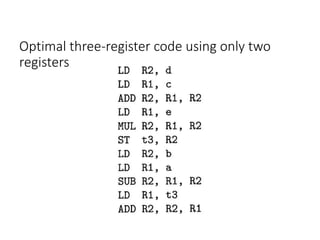
  • 23. Optimal three-register code using only two registers
  • 24. Syntax tree for (a-b)+c*(d/e) with cost vector at each node
  • 25. minimum cost of evaluating the root with two registers available • Compute the left subtree with two registers available into register R0, compute the right subtree with one register available into register R1, and use the instruction ADD R0, R0, R1 to compute the root. This sequence has cost 2+5+1=8. • Compute the right subtree with two registers available into R l , compute the left subtree with one register available into R0, and use the instruction ADD R0, R0, R1. This sequence has cost 4+2+1=7. • Compute the right subtree into memory location M, compute the left subtree with two registers available into register RO, and use the instruction ADD R0, R0, M. This sequence has cost 5+2+1=8.