2. Introduction to the processor
Processors come in many types and with many intended uses.
This chapter contains details about processor design issues, especially for
advanced processors in high - performance applications
Clearly, controllers, embedded controllers, digital signal processors (DSPs), are the
dominant processor types, providing the focus for much of the processor design
effort.
SOC and larger microcontrollers is growing at almost three times that of
microprocessor units (MPUs in Figure 3.2 ).
Especially in SOC type applications, the processor itself is a small component
occupying just a few percent of the die. SOC designs often use many different
types of processors suiting the application.
8. PROCESSOR SELECTION FOR SOC
For many SOC design situations, the selection of the processor is the most obvious task
and, in some ways, the most restricted.
The processor must run a specific system software, so at least a core processor —
usually a general purpose processor (GPP) — must be selected for this function.
9. Processor selection for soc
Figure 3.3 shows the processor model used in the initial design process.
1. Define the Application Requirements
Before selecting a processor, determine:
Target Device: Smartphone, IoT device, automotive system, embedded
system, etc.
Performance Needs: High performance (gaming, AI), balanced
(smartphones, laptops), or low-power (IoT, wearables).
Power Constraints: Battery-powered (low power) vs. plug-in devices (higher
power acceptable).
Connectivity: 5G, Wi-Fi, Bluetooth, or wired interfaces.
Security: Secure Boot, TPM, or dedicated security cores.
11. Processor selection for soc
Soft Processors
The term “ soft core ” refers to an instruction processor design in bit stream
format that can be used to program a field programmable gate array (FPGA)
device. The 4 main reasons for using such designs, despite their large area
power – time cost, are
1. cost reduction in terms of system - level integration,
2. design reuse in cases where multiple designs are really just variations on one,
3. creating an exact fi t for a microcontroller/peripheral combination, and
4. providing future protection against discontinued microcontroller variants.
13. BASIC CONCEPTS IN PROCESSOR ARCHITECTURE
The processor architecture consists of the instruction set of the processor.
While the instruction set implies many implementation (microarchitecture) details, the resulting
implementation is a great deal more than the instruction set.
It is the synthesis of the physical device limitations with area – time – power trade - offs to
optimize specified user requirements.
Instruction Set
The instruction set for most processors is based upon a register set to hold operands and
addresses
The register set size varies from 8 to 64 words or more, each word consisting of 32 – 64 bits.
An additional set of floating - point registers (32 – 128 bits) is usually also available.
Common instruction sets can be classified by format differences into two basic types, the load
– store ( L/S ) architecture and the register – memory ( R/M ) architecture:
16. BASIC CONCEPTS IN PROCESSOR ARCHITECTURE
The L/S instruction set includes the RISC microprocessors. Arguments must be
in registers before execution.
A Load/Store (L/S) architecture is a type of Reduced Instruction Set Computing
(RISC) design where memory access is restricted to specific Load (L) and Store
(S) instructions. Unlike Complex Instruction Set Computing (CISC) architectures
(e.g., x86), where data can be processed directly from memory, L/S
architectures require data to be first loaded into registers before processing.
A Register-Memory Instruction Set refers to a type of CPU architecture where
instructions can operate directly on data stored in memory without requiring
explicit load/store operations. This contrasts with Load/Store (RISC)
architectures, where all operations must first load data into registers.
17. Trade-offs in Instruction Set Architecture (ISA)
The Instruction Set Architecture (ISA) defines how a processor executes
instructions, impacting performance, power efficiency, and complexity.
Different ISAs, such as RISC (Reduced Instruction Set Computing) and CISC
(Complex Instruction Set Computing), have trade-offs based on design
goals.
21. Interrupts and Exceptions
Interrupts and exceptions allow a processor to respond to events such as hardware
signals, errors, and system calls. These mechanisms help in efficient multitasking, error
handling, and real-time processing.
Types of Interrupts
A. Hardware Interrupts (Triggered by external devices)
Maskable Interrupts (IRQ) → Can be ignored or delayed by disabling interrupts.
Non-Maskable Interrupts (NMI) → Cannot be ignored (e.g., power failure).
Interrupt Requests (IRQs) → Devices send requests via the Interrupt Controller (PIC/APIC).
22. How Interrupts Are Handled?
Interrupt Occurs → Device or software sends an interrupt signal.
Processor Saves State → Stores registers and program counter (PC).
Interrupt Vector Table (IVT) Lookup → Finds the correct handler for the
interrupt.
Interrupt Service Routine (ISR) Executes → Handles the event (e.g., reading
from a device).
processor Restores State → Resumes execution of the interrupted program.
23. Types of Exceptions
A. Faults (Can be recovered; program restarts)
Page Fault (Accessing invalid memory).
Divide-by-Zero Error (Mathematical errors).
Traps (Handled immediately and continue execution)
System Calls (Used by OS to switch from user mode to kernel mode).
Aborts (Serious errors that terminate execution)
Hardware failures (e.g., memory corruption).
24. How Exceptions Are Handled?
CPU detects an exception (e.g., invalid instruction, divide-by-zero).
Exception Vector Table Lookup → Finds the correct handler
Exception Handler Executes → Fixes the issue or terminates the program
Interrupts allow devices and software to interact with the CPU asynchronously.
Exceptions handle errors and system events synchronously.
Efficient handling using interrupt controllers and prioritization is crucial for
performance.
Modern CPUs optimize interrupt handling using vectored and fast interrupts.
25. Interrupts and Exceptions Using Condition Codes
Condition codes (also called status flags) are special bits in a processor's status register
(flag register) that indicate the result of arithmetic and logical operations. These flags help
determine whether an interrupt or exception should be triggered.
Common Condition Codes in a Processor
Zero Flag (ZF) – Set when the result of an operation is zero.
Carry Flag (CF) – Set when an arithmetic operation results in a carry (for unsigned numbers).
Overflow Flag (OF) – Set when an arithmetic operation results in an overflow (for signed
numbers).
Sign Flag (SF) – Set if the result of an operation is negative.
Parity Flag (PF) – Set if the result has an even number of 1s in binary.
26. BASIC CONCEPTS IN PROCESSOR MICROARCHITECTURE
Almost all modern processors use an instruction execution pipeline design.
Simple processors issue only one instruction for each cycle;
Many embedded and some signal processors use a simple issue - one -
instruction per - cycle design approach.
others issue many. Many embedded and some signal processors use a
simple issue - one - instruction per - cycle design approach.
But the bulk of modern desktop, laptop, and server systems issue multiple
instructions for each cycle.
Every processor (Figure 3.7 ) has a memory system, execution unit (data
paths), and instruction unit.
27. BASIC CONCEPTS IN PROCESSOR
MICROARCHITECTURE
The pipeline mechanism or control has many possibilities. Potentially, it can
execute one or more instructions for each cycle. Instructions may or may not be
decoded and/or executed in program order
Regardless of the type of pipeline, “ breaks ” or delays are the major limit on
performance.
1. Pipeline
A technique used to improve instruction throughput by breaking execution into
stages.
Common pipeline stages: Fetch, Decode, Execute, Memory Access, Write back.
Example: A 5-stage pipeline in RISC processors.
30. BASIC CONCEPTS IN PROCESSOR MICROARCHITECTURE
The Instruction Register (IR) is a special-purpose register in a computer's central
processing unit (CPU) that holds the instruction currently being executed or
decoded. It is a crucial part of the instruction cycle in a computer.
Functions of the Instruction Register:
Holds the Current Instruction – The IR temporarily stores the machine instruction
fetched from memory.
instruction Buffer
An Instruction Buffer is a temporary storage unit in a CPU that holds multiple
instructions before they are executed. It is mainly used to improve instruction
processing speed by reducing delays in fetching instructions from memory.
33. Execution Unit (EU) in a CPU
The Execution Unit (EU) is the part of the CPU responsible for processing and
executing instructions. It works in conjunction with the Control Unit (CU), which
fetches and decodes instructions before passing them to the Execution Unit.
Components of the Execution Unit
Arithmetic Logic Unit (ALU)
Performs arithmetic (addition, subtraction, multiplication, division).
Executes logical operations (AND, OR, XOR, NOT).
Handles bitwise shifts, comparisons, and Boolean logic.
34. Floating-Point Unit (FPU)
Specializes in floating-point arithmetic (decimal operations).
Follows the IEEE 754 standard for high-precision calculations.
Floating-Point Unit (FPU)
Specializes in floating-point arithmetic (decimal operations).
Follows the IEEE 754 standard for high-precision calculations.
35. BASIC ELEMENTS IN INSTRUCTION HANDLING
An instruction unit consists of the state registers as defined by the instruction set
— the instruction register — plus the instruction buffer, decoder, and an interlock
unit.
The instruction buffer ’ s function is to fetch instructions into registers so that
instructions can be rapidly brought into a position to be decoded.
The decoder has the responsibility for controlling the cache, ALU, registers, and
so on.
Interlock in a Processor
In a processor, an interlock is a hardware or control mechanism that prevents a
subsequent instruction from executing until a previous instruction has completed,
thereby avoiding data hazards or structural conflicts.
38. Instruction decoder and interlocks
Instruction Decoder in a Processor
The Instruction Decoder is a key component of the Control Unit (CU) in a CPU. It
translates the machine code instructions fetched from memory into signals that control
other parts of the processor, such as the Arithmetic Logic Unit (ALU), registers, and
memory access units.
1. Role of the Instruction Decoder
The Instruction Decoder is responsible for: Decoding the instruction opcode – Identifies
the type of operation (ADD, SUB, LOAD, etc.).
Extracting operands – Determines source and destination registers or memory
addresses.
Generating control signals – Activates ALU, memory, and register operations.
Determining instruction format – Identifies whether it's R-type, I-type, etc.
•Determines whether the instruction requires immediate values, registers, or memory access.
39. How the Instruction Decoder Works
Instruction Fetch – The instruction is fetched from memory by the Instruction
Fetch Unit (IFU).
Instruction Decode – The Instruction Decoder analyzes the opcode and
operands.
Control Signal Generation – The decoder sends signals to activate ALU,
registers, or memory units.
Execution – The decoded instruction is executed in the Execution Unit (EU).
40. Instruction decoder and interlocks
Interlock in Instruction Decoder
An interlock in an instruction decoder is a control mechanism that
prevents the execution of an instruction until all necessary conditions (like
data availability, resource availability, or hazard resolution) are met. This
helps avoid errors due to pipeline hazards or data dependencies.
1. Why Interlocks Are Needed in Instruction Decoding
The instruction decoder translates binary machine code into control signals
for execution. However, certain conditions may require an instruction to
pause (stall) before proceeding:
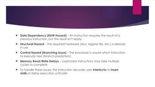
41. Data Dependency (RAW Hazard) – An instruction requires the result of a
previous instruction, but the result isn't ready.
Structural Hazard – The required hardware (ALU, register file, etc.) is already
in use
Control Hazard (Branching Issue) – The processor is unsure which instruction
to execute next (branch prediction).
Memory Read/Write Delays – Load/store instructions may take multiple
cycles to complete.
To handle these issues, the instruction decoder uses interlocks to insert
stalls or delay execution until safe.
42. How Interlocks Work in the Instruction
Decoder
Instruction Fetch – The CPU fetches an instruction from memory.
Instruction Decode – The decoder identifies the instruction type and operands.
Dependency Check (Hazard Detection Unit) – The decoder checks if the
instruction can execute immediately or needs to wait.
Interlock Activation (if needed)
If dependencies exist, an interlock mechanism inserts a stall (delay cycle).
If no dependency exists, the instruction proceeds to execution.
Execution / Stall Handling – If stalled, the CPU waits; otherwise, execution
proceeds.
44. Buffers minimizing pipeline delays
Why Buffers Are Needed in Pipelining?
When an instruction moves through the pipeline, different stages (Fetch,
Decode, Execute, Memory Access, Write Back) require time and
resources. If an instruction needs data that is not yet available, it creates a
stall (pipeline delay).
Buffers store intermediate values between stages to prevent stalling.
They reduce dependency issues by keeping temporary results available for
the next stage.
They improve instruction throughput, making execution faste
45. MORE ROBUST PROCESSORS: VECTOR, VERY LONG INSTRUCTION WORD
( VLIW ), AND SUPERSCALAR
To go beyond one cycle per instruction (CPI), the processor must be able
to execute multiple instructions at the same time.
. Concurrent processors must be able to make simultaneous accesses to
instruction and data memory and to simultaneously execute multiple
operations.
Processors that achieve a higher degree of concurrency are called
concurrent processors, short for processors with instruction - level
concurrency.
46. VECTOR PROCESSORS AND VECTOR INSTRUCTION
EXTENSIONS
Vector instructions boost performance by
reducing the number of instructions required to execute a program (they
reduce the I - bandwidth);
organizing data into regular sequences that can be effi ciently handled by
the hardware; and
Vector processing requires extensions to the instruction set, together with
(for best performance) extensions to the functional units, the register sets,
and particularly to the memory of the system
48. Vector processors usually include vector register (VR) hardware to decou ple
arithmetic processing from memory
Vector Functional Units
The VRs typically consist of eight or more register sets, each consisting of 16 –
64 vector elements, where each vector element is a fl oating - point word.
The VRs access memory with special load and store instructions.
The vector execution units are usually arranged as an independent
functional unit for each instruction class. These might include
add/subtract, • multiplication, • division or reciprocal, and • logical
operations, including compare.
49. Since the purpose of the vector vocabulary is to manage operations over a
vector of operands, once the vector operation is begun, it can continue at
the cycle rate of the system.
The advantage of vector processing is that fewer instructions are required to
execute the vector operations.
Vector Registers: What They Are & How They Work
A vector register is a special type of CPU register that holds entire vectors
(arrays of data) instead of single scalar values. These registers are used in
vector processors and SIMD (Single Instruction, Multiple Data) architectures to
enable parallel processing of multiple data elements in a single instruction.
50. Example: Scalar vs. Vector Registers
Let’s say we want to add two arrays:
A=[1,2,3,4],B=[5,6,7,8]
Scalar Processor (Using Scalar Registers)
Load 1 into a scalar register.
Load 5 into another scalar register.
Perform addition (1+5) and store the result.
Repeat for the remaining elements.
Takes 4 cycles (one per operation).
51. vector Processor (Using Vector Registers)
Load entire A array into a vector register.
Load entire B array into another vector register.
Perform vector addition on all elements at once.
Takes 1 cycle (all 4 operations happen in parallel).
Features of Vector Registers.
Store Multiple Data Elements – Instead of a single value, they store an array.
Optimized for Parallel Execution – Allow SIMD processing.
Reduce Memory Access Time – Fewer loads and stores compared to scalar registers.
Accelerate Computation – Common in AI, graphics, and scientific computing.


![ Example: Scalar vs. Vector Registers
Let’s say we want to add two arrays:
A=[1,2,3,4],B=[5,6,7,8]
Scalar Processor (Using Scalar Registers)
Load 1 into a scalar register.
Load 5 into another scalar register.
Perform addition (1+5) and store the result.
Repeat for the remaining elements.
Takes 4 cycles (one per operation).](https://image.slidesharecdn.com/processors-250517044518-18ad2a76/85/Processors-topic-in-system-on-chip-architecture-50-320.jpg)


