1
Faculty of Engineering & Information Technology
Al-AZHAR UNIVERSITY
Programmable Logic Controllers
( ITCE 5319 )
Introduction to PLCs
(Chapter 1)
Instructor: Eng. Mohammad Aqel
Second Semester, 2007/2008
2
What is a PLC?
• Is a microprocessor base controller that uses a
programmable memory to store instructions and to
implement functions such as logic, timing, counting in
order to control machines .
• Input devices, e.g. sensors such as switches, and output
devices in the system being controlled, e.g. motor, valves,
etc., are connected to the PLC.
• The operator enters a sequence of instructions e.g. ladder
logic diagram. The program then is downloaded into the
memory of the PLC. The controller monitors the inputs’
status and outputs’ status according to this program and
carries out the control rules for which it has been
programmed.
3
• In a traditional industrial control system, all
control devices are wired directly to each other .
In a PLC system, however, the PLC replaces the
wiring between the devices.
• Instead of being wired directly to each other, all
equipment is wired to the PLC. Then, the control
program inside the PLC provides the "wiring"
connection between the devices.
• The control program is the computer program
stored in the PLC’s memory that tells the PLC
what’s supposed to be going on in the system.
• The use of a PLC to provide the wiring
connections between system devices is called
softwiring.
4
WHY USE PLCS?
• Softwiring makes changes in the control system easy and
cheap.
• If you want a device in a PLC system to behave differently
or to control a different process element, all you have to do
is change the control program. In a traditional system,
making this type of change would involve physically
changing the wiring between the devices.
• Flexibility: software based system
• Compact: replace hundreds of relays, timers and counters
• Reliable: less mechanical parts
• reduced costs
5
BUT WHAT EXACTLY IS A PLC?
A PLC basically consists of two elements:
• the central processing unit (CPU)
• the input/output (I/O) system
6
The Central Processing Unit
• is the part of a programmable controller
that retrieves, decodes, stores, and
processes information.
• It also executes the control program stored
in the PLC’s memory.
• In essence, the CPU is the "brains" of a
programmable controller.
7
The CPU has three parts:
• the processor
• the memory system
• the power supply
• The processor is the section of the CPU that codes,
decodes, and computes data.
• The memory system is the section of the CPU that
stores both the control program and data from the
equipment connected to the PLC.
• The power supply is the section that provides the PLC
with the voltage and current it needs to operate.
8
The Input/Output System
• The input/output unit provides the interface
between the system and the outside world,
allowing for connections to be made through
input/output channels to input devices and
output devices
• Every input and output point has a unique I/O
address which can be recognized by the CPU.
• If the CPU can be thought of as the brains of a
PLC, then the I/O system can be thought of as
the arms and legs.
9
A LITTLE MORE ABOUT INPUTS
AND OUTPUTS
All of the field devices connected to a PLC can be
classified in one of two categories:
• inputs • outputs
• Inputs are devices that supply a signal/data to a PLC.
Typical examples of inputs are push buttons, switches,
and measurement de-vices.
• Outputs are devices that await a signal/data from the
PLC to perform their control functions. Lights, horns,
motors, and valves
10
• There are two basic types of input and output
devices:
• discrete • analog
• Discrete devices are inputs and outputs that have
only two states: on and off.
A 1 means that the device is on and a 0 means that
the device is off.
• Analog devices are inputs and outputs that can
have an infinite number of states. These devices
can not only be on and off, but they can also be
barely on, almost totally on, not quite off, etc.
11
AND A LITTLE MORE ABOUT
THE CONTROL PROGRAM
• The control program is a software program in the PLC’s
memory.
• The control program is made up of things called instructions.
• Instructions are little computer codes that make the inputs and
outputs as what you want the result, such as (add and
subtract data, time and count events, compare information,
etc.).
• remember, changing the system is a snap (fast). If you want
the system to act differently, just change the instructions in the
control program.
• all PLCs use two basic types of instructions:
• contacts • coils
12
Contacts & Coils
• Contacts are instructions that refer to the input
conditions to the control program—that is, to the
information supplied by the input field devices .
• The contact waits for the input to do something
in particular (e.g., turn on, turn off).
• Coils are instructions that refer to the outputs of
the control program to what each particular
output device is supposed to do in the system.
13
Ladder Logic
• Ladder logic is the main programming method
used for PLCs.
• ladder logic has been developed to mimic (like)
relay logic.
• By selecting ladder logic as the main
programming method, the amount of retraining
needed for engineers and tradespeople was
greatly reduced.
• A relay is a simple device that uses a magnetic
field to control a switch, as pictured in next slide.
14
normally
open
normally
closed
input coil
OR
OR
•The contact that closes when
the coil is energized is called
normally open.
•The normally closed contacts
touch when the input coil is not
energized.
•Relays are normally drawn in
schematic form using a circle to
represent the input coil. The
output contacts are shown with
two parallel lines.
•Normally open contacts are
shown as two lines, Normally
closed contacts are shown with
two lines with a diagonal line
through them.
15
Example of a Relay
115V
AC
wallplug
relaylogic
input A
(normally closed)
input B
(normally open)
output C
(normally open)
ladder logic
A B C
•The first relay on the left is
used as normally closed, and
will allow current to flow until a
voltage is applied to the input A.
•The second relay is normally
open and will not allow current
to flow until a voltage is applied
to the input B.
•If current is flowing through
the first two relays then current
will flow through the coil in the
third relay, and close the switch
for output C.
•Ladder logic form, This can be
read logically as C will be on if A
is off and B is on.
16
Relay Logic In PLC
ladder
power
supply
+24V
com.
inputs
outputs
push buttons
logic
PLC
AC power
115V
a c
neut.
A B C
light
17
A Seal-in Circuit
• Many relays also have multiple outputs and this allows
an output relay to also be an input simultaneously.
• The input B will only be on when the output B is on. If B
is off, and A is energized, then B will turn on.
18
Reading Ladder Logic
HOT NEUTRAL
INPUTS OUTPUTS
A B X
C D
E F
G
H
Y
Note:Power needs to flow through some combination of the inputs
(A,B,C,D,E,F,G,H) to turn on outputs (X,Y).
• In the figure there are two rungs, and on each rung there are
combinations of inputs (two vertical lines) and outputs (circles).
• If the inputs are opened or closed in the right combination the power
can flow from the hot rail, through the inputs, to power the outputs,
and finally to the neutral rail.
•In the top rung the contacts are normally open and normally closed.
Which means if input A is on and input B is off, then power will flow
through the output and activate it. Any other combination of input
values will result in the output X being off.
• The second rung of Figure is
more complex, there are
actually multiple combinations
of inputs that will result in the
output Y turning on.
19
Mnemonics
• This is other method for
programming PLCs.
• An example of mnemonics is
shown in Figure. In this example
the instructions are read one line at
a time from top to bottom.
20
Sequential Function Chart
Start
End
power up
power down
flash
Executionfollows
multiple paths
• Sequential Function Charts (SFCs)
have been developed for the
programming of more advanced
systems.
•Power up , power down , flash : is
functions .
•Each function is a small ladder logic
program.
21
PLC Connections
• When a process is controlled by a PLC it uses inputs from sensors
to make decisions and update outputs to drive actuators, as shown
in Figure below.
• The control loop is a continuous cycle
of the PLC reading inputs, solving the
ladder logic, and then changing the
outputs.
•When power is turned on initially the
PLC does a quick check to ensure that
the hardware is working properly.
•If there is a problem the PLC will halt
and indicate there is an error. For
example, if the PLC backup battery is
low and power was lost, the memory
will be corrupt
22
CASE STUDY
• Problem: Try to develop a ladder logic diagram
that will allow three switches in a room to control
a single light.
?
23
Solution1
• Solution: There are two possible approaches to this
problem. The first assumes that any one of the switches
on will turn on the light, but all three switches must be off
for the light to be off.
24
Solution2
• The second solution assumes that each switch can turn the light on or
off, regardless of the states of the other switches.
• This method is more complex and involves thinking through all of the
possible combinations of switch positions.
25
Summary
• Normally open and closed contacts.
• Relays and their relationship to ladder
logic.
• PLC outputs can be inputs, as shown by
the seal in circuit.
• Programming can be done with ladder
logic, mnemonics, SFCs.
• There are multiple ways to write a PLC
program.
26
ASSIGNMENT PROBLEM
• Develop a simple ladder logic program
that will turn on an output X if inputs A and
B, or input C is on.

More Related Content

PPTX
Programmable Logic Controller
PPTX
Lecture_PLC_Week for industialization in plc
DOCX
Plc notes
PPT
PLC PPT.ppt
PDF
D. CHAPTER dffrtgfffffffgggfffdddFIVE.pdf
PPTX
Plc (PROGRAMMABLE LOGIC CONTROLLER)
PPTX
PDF
Lecture 10.cont,11 (plc)
Programmable Logic Controller
Lecture_PLC_Week for industialization in plc
Plc notes
PLC PPT.ppt
D. CHAPTER dffrtgfffffffgggfffdddFIVE.pdf
Plc (PROGRAMMABLE LOGIC CONTROLLER)
Lecture 10.cont,11 (plc)

Similar to Programmable_Logic_Controllers_Introduction_to_PLCs__(Chapter_1)_Lec1.ppt (20)

PDF
Introduction to PLC
PPTX
plc_scada.pptx
PPT
ie450pp10.ppt
PPT
PLC good.ppt
PPT
PLC.ppt
PPT
ie450pp10.ppt
PPT
ie450pp10.ppt
PPT
PLC (PROGRAMMABLE LOGIC CONTROLLER)
PPT
ie450pp10.ppt
PPT
PLC, or Programmable Logic Controller, is a specialized industrial computer u...
PPT
ie450pp10.ppt
PPT
Basics of Programmable Logic Controllers and Signals
PDF
PLCProgramming for beginners in automation
PPT
Evolution of Programmable Logic Controllers
PPT
plc1.ppt
PPT
ie450pp10.ppt
PPT
PLC Basics
PPT
Introduction to PLC
PPTX
Unit 4 - PLC.pptx
PDF
PLC-converted.pdf
Introduction to PLC
plc_scada.pptx
ie450pp10.ppt
PLC good.ppt
PLC.ppt
ie450pp10.ppt
ie450pp10.ppt
PLC (PROGRAMMABLE LOGIC CONTROLLER)
ie450pp10.ppt
PLC, or Programmable Logic Controller, is a specialized industrial computer u...
ie450pp10.ppt
Basics of Programmable Logic Controllers and Signals
PLCProgramming for beginners in automation
Evolution of Programmable Logic Controllers
plc1.ppt
ie450pp10.ppt
PLC Basics
Introduction to PLC
Unit 4 - PLC.pptx
PLC-converted.pdf
Ad

Recently uploaded (20)

PPTX
ARCHITECTURE AND PROGRAMMING OF EMBEDDED SYSTEMS
PDF
Using Technology to Foster Innovative Teaching Practices (www.kiu.ac.ug)
PPTX
Wireless sensor networks (WSN) SRM unit 2
PDF
Mechanics of materials week 2 rajeshwari
PDF
AIGA 012_04 Cleaning of equipment for oxygen service_reformat Jan 12.pdf
PDF
IAE-V2500 Engine Airbus Family A319/320
PDF
ECT443_instrumentation_Engg_mod-1.pdf indroduction to instrumentation
PDF
Engineering Solutions for Ethical Dilemmas in Healthcare (www.kiu.ac.ug)
PDF
Cryptography and Network Security-Module-I.pdf
PDF
Principles of operation, construction, theory, advantages and disadvantages, ...
DOCX
ENVIRONMENTAL PROTECTION AND MANAGEMENT (18CVL756)
PPT
UNIT-I Machine Learning Essentials for 2nd years
PPTX
CS6006 - CLOUD COMPUTING - Module - 1.pptx
PDF
VTU IOT LAB MANUAL (BCS701) Computer science and Engineering
PDF
MACCAFERRY GUIA GAVIONES TERRAPLENES EN ESPAÑOL
PPTX
Software-Development-Life-Cycle-SDLC.pptx
PPTX
Module1.pptxrjkeieuekwkwoowkemehehehrjrjrj
PDF
Performance, energy consumption and costs: a comparative analysis of automati...
PDF
ASPEN PLUS USER GUIDE - PROCESS SIMULATIONS
PPTX
Design ,Art Across Digital Realities and eXtended Reality
ARCHITECTURE AND PROGRAMMING OF EMBEDDED SYSTEMS
Using Technology to Foster Innovative Teaching Practices (www.kiu.ac.ug)
Wireless sensor networks (WSN) SRM unit 2
Mechanics of materials week 2 rajeshwari
AIGA 012_04 Cleaning of equipment for oxygen service_reformat Jan 12.pdf
IAE-V2500 Engine Airbus Family A319/320
ECT443_instrumentation_Engg_mod-1.pdf indroduction to instrumentation
Engineering Solutions for Ethical Dilemmas in Healthcare (www.kiu.ac.ug)
Cryptography and Network Security-Module-I.pdf
Principles of operation, construction, theory, advantages and disadvantages, ...
ENVIRONMENTAL PROTECTION AND MANAGEMENT (18CVL756)
UNIT-I Machine Learning Essentials for 2nd years
CS6006 - CLOUD COMPUTING - Module - 1.pptx
VTU IOT LAB MANUAL (BCS701) Computer science and Engineering
MACCAFERRY GUIA GAVIONES TERRAPLENES EN ESPAÑOL
Software-Development-Life-Cycle-SDLC.pptx
Module1.pptxrjkeieuekwkwoowkemehehehrjrjrj
Performance, energy consumption and costs: a comparative analysis of automati...
ASPEN PLUS USER GUIDE - PROCESS SIMULATIONS
Design ,Art Across Digital Realities and eXtended Reality
Ad

Programmable_Logic_Controllers_Introduction_to_PLCs__(Chapter_1)_Lec1.ppt

  • 1. 1 Faculty of Engineering & Information Technology Al-AZHAR UNIVERSITY Programmable Logic Controllers ( ITCE 5319 ) Introduction to PLCs (Chapter 1) Instructor: Eng. Mohammad Aqel Second Semester, 2007/2008
  • 2. 2 What is a PLC? • Is a microprocessor base controller that uses a programmable memory to store instructions and to implement functions such as logic, timing, counting in order to control machines . • Input devices, e.g. sensors such as switches, and output devices in the system being controlled, e.g. motor, valves, etc., are connected to the PLC. • The operator enters a sequence of instructions e.g. ladder logic diagram. The program then is downloaded into the memory of the PLC. The controller monitors the inputs’ status and outputs’ status according to this program and carries out the control rules for which it has been programmed.
  • 3. 3 • In a traditional industrial control system, all control devices are wired directly to each other . In a PLC system, however, the PLC replaces the wiring between the devices. • Instead of being wired directly to each other, all equipment is wired to the PLC. Then, the control program inside the PLC provides the "wiring" connection between the devices. • The control program is the computer program stored in the PLC’s memory that tells the PLC what’s supposed to be going on in the system. • The use of a PLC to provide the wiring connections between system devices is called softwiring.
  • 4. 4 WHY USE PLCS? • Softwiring makes changes in the control system easy and cheap. • If you want a device in a PLC system to behave differently or to control a different process element, all you have to do is change the control program. In a traditional system, making this type of change would involve physically changing the wiring between the devices. • Flexibility: software based system • Compact: replace hundreds of relays, timers and counters • Reliable: less mechanical parts • reduced costs
  • 5. 5 BUT WHAT EXACTLY IS A PLC? A PLC basically consists of two elements: • the central processing unit (CPU) • the input/output (I/O) system
  • 6. 6 The Central Processing Unit • is the part of a programmable controller that retrieves, decodes, stores, and processes information. • It also executes the control program stored in the PLC’s memory. • In essence, the CPU is the "brains" of a programmable controller.
  • 7. 7 The CPU has three parts: • the processor • the memory system • the power supply • The processor is the section of the CPU that codes, decodes, and computes data. • The memory system is the section of the CPU that stores both the control program and data from the equipment connected to the PLC. • The power supply is the section that provides the PLC with the voltage and current it needs to operate.
  • 8. 8 The Input/Output System • The input/output unit provides the interface between the system and the outside world, allowing for connections to be made through input/output channels to input devices and output devices • Every input and output point has a unique I/O address which can be recognized by the CPU. • If the CPU can be thought of as the brains of a PLC, then the I/O system can be thought of as the arms and legs.
  • 9. 9 A LITTLE MORE ABOUT INPUTS AND OUTPUTS All of the field devices connected to a PLC can be classified in one of two categories: • inputs • outputs • Inputs are devices that supply a signal/data to a PLC. Typical examples of inputs are push buttons, switches, and measurement de-vices. • Outputs are devices that await a signal/data from the PLC to perform their control functions. Lights, horns, motors, and valves
  • 10. 10 • There are two basic types of input and output devices: • discrete • analog • Discrete devices are inputs and outputs that have only two states: on and off. A 1 means that the device is on and a 0 means that the device is off. • Analog devices are inputs and outputs that can have an infinite number of states. These devices can not only be on and off, but they can also be barely on, almost totally on, not quite off, etc.
  • 11. 11 AND A LITTLE MORE ABOUT THE CONTROL PROGRAM • The control program is a software program in the PLC’s memory. • The control program is made up of things called instructions. • Instructions are little computer codes that make the inputs and outputs as what you want the result, such as (add and subtract data, time and count events, compare information, etc.). • remember, changing the system is a snap (fast). If you want the system to act differently, just change the instructions in the control program. • all PLCs use two basic types of instructions: • contacts • coils
  • 12. 12 Contacts & Coils • Contacts are instructions that refer to the input conditions to the control program—that is, to the information supplied by the input field devices . • The contact waits for the input to do something in particular (e.g., turn on, turn off). • Coils are instructions that refer to the outputs of the control program to what each particular output device is supposed to do in the system.
  • 13. 13 Ladder Logic • Ladder logic is the main programming method used for PLCs. • ladder logic has been developed to mimic (like) relay logic. • By selecting ladder logic as the main programming method, the amount of retraining needed for engineers and tradespeople was greatly reduced. • A relay is a simple device that uses a magnetic field to control a switch, as pictured in next slide.
  • 14. 14 normally open normally closed input coil OR OR •The contact that closes when the coil is energized is called normally open. •The normally closed contacts touch when the input coil is not energized. •Relays are normally drawn in schematic form using a circle to represent the input coil. The output contacts are shown with two parallel lines. •Normally open contacts are shown as two lines, Normally closed contacts are shown with two lines with a diagonal line through them.
  • 15. 15 Example of a Relay 115V AC wallplug relaylogic input A (normally closed) input B (normally open) output C (normally open) ladder logic A B C •The first relay on the left is used as normally closed, and will allow current to flow until a voltage is applied to the input A. •The second relay is normally open and will not allow current to flow until a voltage is applied to the input B. •If current is flowing through the first two relays then current will flow through the coil in the third relay, and close the switch for output C. •Ladder logic form, This can be read logically as C will be on if A is off and B is on.
  • 16. 16 Relay Logic In PLC ladder power supply +24V com. inputs outputs push buttons logic PLC AC power 115V a c neut. A B C light
  • 17. 17 A Seal-in Circuit • Many relays also have multiple outputs and this allows an output relay to also be an input simultaneously. • The input B will only be on when the output B is on. If B is off, and A is energized, then B will turn on.
  • 18. 18 Reading Ladder Logic HOT NEUTRAL INPUTS OUTPUTS A B X C D E F G H Y Note:Power needs to flow through some combination of the inputs (A,B,C,D,E,F,G,H) to turn on outputs (X,Y). • In the figure there are two rungs, and on each rung there are combinations of inputs (two vertical lines) and outputs (circles). • If the inputs are opened or closed in the right combination the power can flow from the hot rail, through the inputs, to power the outputs, and finally to the neutral rail. •In the top rung the contacts are normally open and normally closed. Which means if input A is on and input B is off, then power will flow through the output and activate it. Any other combination of input values will result in the output X being off. • The second rung of Figure is more complex, there are actually multiple combinations of inputs that will result in the output Y turning on.
  • 19. 19 Mnemonics • This is other method for programming PLCs. • An example of mnemonics is shown in Figure. In this example the instructions are read one line at a time from top to bottom.
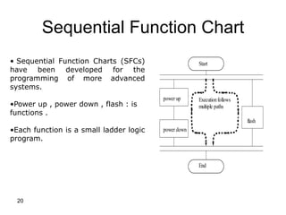
  • 20. 20 Sequential Function Chart Start End power up power down flash Executionfollows multiple paths • Sequential Function Charts (SFCs) have been developed for the programming of more advanced systems. •Power up , power down , flash : is functions . •Each function is a small ladder logic program.
  • 21. 21 PLC Connections • When a process is controlled by a PLC it uses inputs from sensors to make decisions and update outputs to drive actuators, as shown in Figure below. • The control loop is a continuous cycle of the PLC reading inputs, solving the ladder logic, and then changing the outputs. •When power is turned on initially the PLC does a quick check to ensure that the hardware is working properly. •If there is a problem the PLC will halt and indicate there is an error. For example, if the PLC backup battery is low and power was lost, the memory will be corrupt
  • 22. 22 CASE STUDY • Problem: Try to develop a ladder logic diagram that will allow three switches in a room to control a single light. ?
  • 23. 23 Solution1 • Solution: There are two possible approaches to this problem. The first assumes that any one of the switches on will turn on the light, but all three switches must be off for the light to be off.
  • 24. 24 Solution2 • The second solution assumes that each switch can turn the light on or off, regardless of the states of the other switches. • This method is more complex and involves thinking through all of the possible combinations of switch positions.
  • 25. 25 Summary • Normally open and closed contacts. • Relays and their relationship to ladder logic. • PLC outputs can be inputs, as shown by the seal in circuit. • Programming can be done with ladder logic, mnemonics, SFCs. • There are multiple ways to write a PLC program.
  • 26. 26 ASSIGNMENT PROBLEM • Develop a simple ladder logic program that will turn on an output X if inputs A and B, or input C is on.