SlideShare a Scribd company logo
PROGRAMMABLE PERIPHERAL
INTERFACE -8255
Features:
• It is a programmable device.
• It has 24 I/O programmable pins like PA,PB,PC (3-8
pins).
• T T L compatible.
• Improved dc driving capability
Pin Diagram
Function of pins:
• Data bus(D0-D7):These are 8-bit bi-directional buses,
connected to 8085 data bus for transferring data.
• CS: This is Active Low signal. When it is low, then
data is transfer from 8085.
• Read: This is Active Low signal, when it is Low read
operation will be start.
• Write: This is Active Low signal, when it is Low Write
operation will be start.
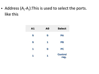
A1A1 A0A0 SelectSelect
00 00 PAPA
00 11 PBPB
11 00 PCPC
11 11
ControlControl
reg.reg.
• Address (A0-A1):This is used to select the ports.
like this
• RESET: This is used to reset the device. That means
clear control registers.
• PA0-PA7:It is the 8-bit bi-directional I/O pins used to
send the data to peripheral or
or to receive the data from peripheral.
• PB0-PB7:Similar to PA
• PC0-PC7:This is also 8-bit bidirectional I/O pins. These
lines are divided into two groups.
1. PC0 to PC3(Lower Groups)
2. PC4 to PC7 (Higher groups)
These two groups working in separately using 4 data’s.
Block Diagram
Data Bus buffer:
• It is a 8-bit bidirectional Data bus.
• Used to interface between 8255 data bus with
system bus.
• The internal data bus and Outer pins D0-D7 pins
are connected in internally.
• The direction of data buffer is decided by
Read/Control Logic.
Read/Write Control Logic:
• This is getting the input signals from control
bus and Address bus
• Control signal are RD and WR.
• Address signals are A0,A1,and CS.
• 8255 operation is enabled or disabled by CS.
Group A and Group B control:
• Group A and B get the Control
Signal from CPU and send the command to the individual
control blocks.
• Group A send the control signal to port A and Port C
(Upper) PC7-PC4.
• Group B send the control signal to port B and Port C
(Lower) PC3-PC0.
• PORT A:
• This is a 8-bit buffered I/O latch.
• It can be programmed by mode 0 , mode 1, mode 2 .
PORT B:
• This is a 8-bit buffer I/O latch.
• It can be programmed by mode 0 and mode 1.
• PORT C:
• This is a 8-bit Unlatched buffer Input and an
Output latch.
• It is splitted into two parts.
• It can be programmed by bit set/reset operation.
Operation modes:
BIT SET/RESET MODE:
• The PORT C can be Set or Reset by sending OUT
instruction to the CONTROL registers.
I/O MODES:
• MODE 0(Simple input / Output):
• In this mode , port A, port B and port C is used as
individually (Simply).
• Features:
• Outputs are latched , Inputs are buffered not latched.
• Ports do not have Handshake or interrupt capability.
• MODE 1 :(Input/output with Hand shake)
• In this mode, input or output is transferred by
hand shaking Signals.
• Handshaking signals is used to transfer data
between whose data transfer is not same.
Computer PrinterDATA BUS
STB
ACK
Busy
• Example:
• The computer send the data to the printer large
speed compared to the printer.
• When computer send the data according to the
printer speed at the time only, printer can accept.
• If printer is not ready to accept the data then
after sending the data bus , computer uses
another handshaking signal to tell printer that
valid data is available on the data bus.
• Each port uses three lines from port C as
handshake signals
MODE 2:bi-directional I/O data transfer:
• This mode allows bidirectional data transfer over
a single 8-bit data bus using handshake signals.
• This feature is possible only Group A
• Port A is working as 8-biy bidirectional.
• PC3-PC7 is used for handshaking purpose.
• The data is sent by CPU through this port , when
the peripheral request it.
• CONTROL WORD FORMATS:
• In the INPUT mode , When RESET is High all 24
pins (3-ports) be a input mode.
• i.e all flip flops are cleared and the interrupts are
rest.
• This condition is maintained even after RESET
goes low.
• This can be avoid by writing single control word to
the control registers , when required.
FOR BIT SET/RESET MODE:
• This is bit set/reset control word format.
X X X
Don’t care
Bit select
B0
B1
B2
D7 D6 D5 D4 D3 D2 D1 D0
0 1 2 3 4 5 6 7
0 1 0 1 0 1 0 1
0 0 1 1 0 0 1 1
0 0 0 0 1 1 1 1
BIT
SET/RESET
1=SET
0=RESET
BIT SET/RESET FLAG
=0 Active
• PC0-PC7 is set or reset as per the status of D0.
• A BSR word is written for each bit
• Example:
• PC3 is Set then control register will be 0XXX0111.
• PC4 is Reset then control register will be
0XXX01000.
• X is a don’t care.
• FOR I/O MODE:
The mode format for I/O as shown in figure
D
7
D
6
D
5
D
4
D
3
D
2
D
1
D
0
Group A
Port C Upper
1=Input
0=Output
Port B
1=Input
0=Output
Mode
selection
00=mode 0
01=mode 1
1x=mode 2
Group B
Port C Lower
1=Input
0=Output
Port B
1=Input
0=Output
Mode selection
0=mode 0
1=mode 1
Mode set
flag=1=Active
Programmableperipheralinterface 8255 ppt
• The control word for both mode is same.
• Bit D7 is used for specifying whether word
loaded in to Bit set/reset mode or Mode
definition word.
• D7=1=Mode definition mode.
• D7=0=Bit set/Reset mode.
Thank you
Q&A

More Related Content

What's hot (20)

PPT
microcontroller basics
sagar Ramdev
 
PPTX
Interfacing with peripherals: analog to digital converters and digital to ana...
NimeshSingh27
 
DOC
8051 Microcontroller Notes
Dr.YNM
 
PPTX
8255 PPI
deval patel
 
PPT
DAC-digital to analog converter
Shazid Reaj
 
PDF
Data types in verilog
Nallapati Anindra
 
PPT
8255 presentaion.ppt
kamlesh deshmukh
 
PPT
Fpga(field programmable gate array)
Iffat Anjum
 
PPT
VLSI subsystem design processes and illustration
Vishal kakade
 
PDF
8253ppt
Bharani Samrat
 
PPT
Arm organization and implementation
Shubham Singh
 
PPTX
Addressing modes of 8086
saurav kumar
 
DOCX
Lambda design rule
Gowri Kishore
 
PDF
Introduction to pic microcontroller
Siva Kumar
 
PDF
Seven segment interfacing with 8051.pdf
Srikrishna Thota
 
DOCX
8086 pin diagram description
Akhil Singal
 
PPT
Introduction to Interrupts of 8085 microprocessor
RAKESHCHOUDHARY164857
 
PPTX
8251 USART
coolsdhanesh
 
PPTX
PIC-18 Microcontroller
ASHISH RANJAN
 
microcontroller basics
sagar Ramdev
 
Interfacing with peripherals: analog to digital converters and digital to ana...
NimeshSingh27
 
8051 Microcontroller Notes
Dr.YNM
 
8255 PPI
deval patel
 
DAC-digital to analog converter
Shazid Reaj
 
Data types in verilog
Nallapati Anindra
 
8255 presentaion.ppt
kamlesh deshmukh
 
Fpga(field programmable gate array)
Iffat Anjum
 
VLSI subsystem design processes and illustration
Vishal kakade
 
Arm organization and implementation
Shubham Singh
 
Addressing modes of 8086
saurav kumar
 
Lambda design rule
Gowri Kishore
 
Introduction to pic microcontroller
Siva Kumar
 
Seven segment interfacing with 8051.pdf
Srikrishna Thota
 
8086 pin diagram description
Akhil Singal
 
Introduction to Interrupts of 8085 microprocessor
RAKESHCHOUDHARY164857
 
8251 USART
coolsdhanesh
 
PIC-18 Microcontroller
ASHISH RANJAN
 

Similar to Programmableperipheralinterface 8255 ppt (20)

PPT
KTU_8255_Programmable Peripheral Interface
roshi4781
 
PPTX
8255 ppi students material for ppi mpmc study
Sirisha Vamsi
 
PPT
8255 class
riyasekaran
 
PPTX
UNIT- 3.pptx
BASKARS53
 
PPTX
UNIT 3 Peripheral Interfacing.pptx
Gowrishankar C
 
PPT
8255-PPI MPMC text book for engineering.ppt
khushiduppala
 
PDF
Unit 3-PROGRAMMABLE PERIPERAL INTERFACE.pdf- MECHATRONICS-ENGGINERING
Chandra Kumar S
 
PDF
unit-3-8255.pdf
ShanmukhSaiR
 
PPT
PPI-MECHATRONICS
selvakumar948
 
PPT
8255 PPI (programmable Peripheral Interface) mode 0
ABHIMANYUJHA8
 
PPT
MECHATRONICS-Unit 3-PROGRAMMABLE PERIPERAL INTERFACE.ppt
CHANDRA KUMAR S
 
PPTX
Unit-3 IO Interfacing-1.pptximportant questions to be noted
mandakalyan811
 
PPTX
8255_Ppi new
Monica Gunjal
 
PPTX
Lec14
siddu kadiwal
 
PPT
UNIT III PROGRAMMABLE PERIPHERAL INTERFACE
ravis205084
 
PPTX
Interfacing of 8255 IC By Er. Swapnil Kaware.
Prof. Swapnil V. Kaware
 
PPTX
8255 Programmable parallel I/O
Muhammed Afsal Villan
 
PPT
20ME702– MECHATRONICS -UNIT-3.ppt
Mohanumar S
 
PPT
Unit 3-PROGRAMMABLE PERIPHERAL INTERFACE-ME6702– MECHATRONICS
Mohanumar S
 
PPTX
Mod-2 M&M.pptx
TechCook1
 
KTU_8255_Programmable Peripheral Interface
roshi4781
 
8255 ppi students material for ppi mpmc study
Sirisha Vamsi
 
8255 class
riyasekaran
 
UNIT- 3.pptx
BASKARS53
 
UNIT 3 Peripheral Interfacing.pptx
Gowrishankar C
 
8255-PPI MPMC text book for engineering.ppt
khushiduppala
 
Unit 3-PROGRAMMABLE PERIPERAL INTERFACE.pdf- MECHATRONICS-ENGGINERING
Chandra Kumar S
 
unit-3-8255.pdf
ShanmukhSaiR
 
PPI-MECHATRONICS
selvakumar948
 
8255 PPI (programmable Peripheral Interface) mode 0
ABHIMANYUJHA8
 
MECHATRONICS-Unit 3-PROGRAMMABLE PERIPERAL INTERFACE.ppt
CHANDRA KUMAR S
 
Unit-3 IO Interfacing-1.pptximportant questions to be noted
mandakalyan811
 
8255_Ppi new
Monica Gunjal
 
UNIT III PROGRAMMABLE PERIPHERAL INTERFACE
ravis205084
 
Interfacing of 8255 IC By Er. Swapnil Kaware.
Prof. Swapnil V. Kaware
 
8255 Programmable parallel I/O
Muhammed Afsal Villan
 
20ME702– MECHATRONICS -UNIT-3.ppt
Mohanumar S
 
Unit 3-PROGRAMMABLE PERIPHERAL INTERFACE-ME6702– MECHATRONICS
Mohanumar S
 
Mod-2 M&M.pptx
TechCook1
 
Ad

Recently uploaded (20)

PPTX
MATLAB : Introduction , Features , Display Windows, Syntax, Operators, Graph...
Amity University, Patna
 
PDF
International Journal of Information Technology Convergence and services (IJI...
ijitcsjournal4
 
PPT
Electrical Safety Presentation for Basics Learning
AliJaved79382
 
PDF
Halide Perovskites’ Multifunctional Properties: Coordination Engineering, Coo...
TaameBerhe2
 
PPTX
Product Development & DevelopmentLecture02.pptx
zeeshanwazir2
 
PDF
Viol_Alessandro_Presentazione_prelaurea.pdf
dsecqyvhbowrzxshhf
 
PPTX
Thermal runway and thermal stability.pptx
godow93766
 
PDF
MAD Unit - 2 Activity and Fragment Management in Android (Diploma IT)
JappanMavani
 
PDF
Zilliz Cloud Demo for performance and scale
Zilliz
 
PDF
Electrical Engineer operation Supervisor
ssaruntatapower143
 
DOC
MRRS Strength and Durability of Concrete
CivilMythili
 
PPTX
Knowledge Representation : Semantic Networks
Amity University, Patna
 
PDF
PORTFOLIO Golam Kibria Khan — architect with a passion for thoughtful design...
MasumKhan59
 
DOCX
8th International Conference on Electrical Engineering (ELEN 2025)
elelijjournal653
 
PDF
Pressure Measurement training for engineers and Technicians
AIESOLUTIONS
 
PPTX
DATA BASE MANAGEMENT AND RELATIONAL DATA
gomathisankariv2
 
DOCX
CS-802 (A) BDH Lab manual IPS Academy Indore
thegodhimself05
 
PPTX
Shinkawa Proposal to meet Vibration API670.pptx
AchmadBashori2
 
PDF
Reasons for the succes of MENARD PRESSUREMETER.pdf
majdiamz
 
PPTX
美国电子版毕业证南卡罗莱纳大学上州分校水印成绩单USC学费发票定做学位证书编号怎么查
Taqyea
 
MATLAB : Introduction , Features , Display Windows, Syntax, Operators, Graph...
Amity University, Patna
 
International Journal of Information Technology Convergence and services (IJI...
ijitcsjournal4
 
Electrical Safety Presentation for Basics Learning
AliJaved79382
 
Halide Perovskites’ Multifunctional Properties: Coordination Engineering, Coo...
TaameBerhe2
 
Product Development & DevelopmentLecture02.pptx
zeeshanwazir2
 
Viol_Alessandro_Presentazione_prelaurea.pdf
dsecqyvhbowrzxshhf
 
Thermal runway and thermal stability.pptx
godow93766
 
MAD Unit - 2 Activity and Fragment Management in Android (Diploma IT)
JappanMavani
 
Zilliz Cloud Demo for performance and scale
Zilliz
 
Electrical Engineer operation Supervisor
ssaruntatapower143
 
MRRS Strength and Durability of Concrete
CivilMythili
 
Knowledge Representation : Semantic Networks
Amity University, Patna
 
PORTFOLIO Golam Kibria Khan — architect with a passion for thoughtful design...
MasumKhan59
 
8th International Conference on Electrical Engineering (ELEN 2025)
elelijjournal653
 
Pressure Measurement training for engineers and Technicians
AIESOLUTIONS
 
DATA BASE MANAGEMENT AND RELATIONAL DATA
gomathisankariv2
 
CS-802 (A) BDH Lab manual IPS Academy Indore
thegodhimself05
 
Shinkawa Proposal to meet Vibration API670.pptx
AchmadBashori2
 
Reasons for the succes of MENARD PRESSUREMETER.pdf
majdiamz
 
美国电子版毕业证南卡罗莱纳大学上州分校水印成绩单USC学费发票定做学位证书编号怎么查
Taqyea
 
Ad

Programmableperipheralinterface 8255 ppt

  • 1. PROGRAMMABLE PERIPHERAL INTERFACE -8255 Features: • It is a programmable device. • It has 24 I/O programmable pins like PA,PB,PC (3-8 pins). • T T L compatible. • Improved dc driving capability
  • 3. Function of pins: • Data bus(D0-D7):These are 8-bit bi-directional buses, connected to 8085 data bus for transferring data. • CS: This is Active Low signal. When it is low, then data is transfer from 8085. • Read: This is Active Low signal, when it is Low read operation will be start. • Write: This is Active Low signal, when it is Low Write operation will be start.
  • 4. A1A1 A0A0 SelectSelect 00 00 PAPA 00 11 PBPB 11 00 PCPC 11 11 ControlControl reg.reg. • Address (A0-A1):This is used to select the ports. like this
  • 5. • RESET: This is used to reset the device. That means clear control registers. • PA0-PA7:It is the 8-bit bi-directional I/O pins used to send the data to peripheral or or to receive the data from peripheral. • PB0-PB7:Similar to PA • PC0-PC7:This is also 8-bit bidirectional I/O pins. These lines are divided into two groups. 1. PC0 to PC3(Lower Groups) 2. PC4 to PC7 (Higher groups) These two groups working in separately using 4 data’s.
  • 7. Data Bus buffer: • It is a 8-bit bidirectional Data bus. • Used to interface between 8255 data bus with system bus. • The internal data bus and Outer pins D0-D7 pins are connected in internally. • The direction of data buffer is decided by Read/Control Logic.
  • 8. Read/Write Control Logic: • This is getting the input signals from control bus and Address bus • Control signal are RD and WR. • Address signals are A0,A1,and CS. • 8255 operation is enabled or disabled by CS.
  • 9. Group A and Group B control: • Group A and B get the Control Signal from CPU and send the command to the individual control blocks. • Group A send the control signal to port A and Port C (Upper) PC7-PC4. • Group B send the control signal to port B and Port C (Lower) PC3-PC0. • PORT A: • This is a 8-bit buffered I/O latch. • It can be programmed by mode 0 , mode 1, mode 2 .
  • 10. PORT B: • This is a 8-bit buffer I/O latch. • It can be programmed by mode 0 and mode 1. • PORT C: • This is a 8-bit Unlatched buffer Input and an Output latch. • It is splitted into two parts. • It can be programmed by bit set/reset operation.
  • 11. Operation modes: BIT SET/RESET MODE: • The PORT C can be Set or Reset by sending OUT instruction to the CONTROL registers. I/O MODES: • MODE 0(Simple input / Output): • In this mode , port A, port B and port C is used as individually (Simply). • Features: • Outputs are latched , Inputs are buffered not latched. • Ports do not have Handshake or interrupt capability.
  • 12. • MODE 1 :(Input/output with Hand shake) • In this mode, input or output is transferred by hand shaking Signals. • Handshaking signals is used to transfer data between whose data transfer is not same. Computer PrinterDATA BUS STB ACK Busy
  • 13. • Example: • The computer send the data to the printer large speed compared to the printer. • When computer send the data according to the printer speed at the time only, printer can accept. • If printer is not ready to accept the data then after sending the data bus , computer uses another handshaking signal to tell printer that valid data is available on the data bus. • Each port uses three lines from port C as handshake signals
  • 14. MODE 2:bi-directional I/O data transfer: • This mode allows bidirectional data transfer over a single 8-bit data bus using handshake signals. • This feature is possible only Group A • Port A is working as 8-biy bidirectional. • PC3-PC7 is used for handshaking purpose. • The data is sent by CPU through this port , when the peripheral request it. • CONTROL WORD FORMATS: • In the INPUT mode , When RESET is High all 24 pins (3-ports) be a input mode.
  • 15. • i.e all flip flops are cleared and the interrupts are rest. • This condition is maintained even after RESET goes low. • This can be avoid by writing single control word to the control registers , when required.
  • 16. FOR BIT SET/RESET MODE: • This is bit set/reset control word format. X X X Don’t care Bit select B0 B1 B2 D7 D6 D5 D4 D3 D2 D1 D0 0 1 2 3 4 5 6 7 0 1 0 1 0 1 0 1 0 0 1 1 0 0 1 1 0 0 0 0 1 1 1 1 BIT SET/RESET 1=SET 0=RESET BIT SET/RESET FLAG =0 Active
  • 17. • PC0-PC7 is set or reset as per the status of D0. • A BSR word is written for each bit • Example: • PC3 is Set then control register will be 0XXX0111. • PC4 is Reset then control register will be 0XXX01000. • X is a don’t care.
  • 18. • FOR I/O MODE: The mode format for I/O as shown in figure D 7 D 6 D 5 D 4 D 3 D 2 D 1 D 0 Group A Port C Upper 1=Input 0=Output Port B 1=Input 0=Output Mode selection 00=mode 0 01=mode 1 1x=mode 2 Group B Port C Lower 1=Input 0=Output Port B 1=Input 0=Output Mode selection 0=mode 0 1=mode 1 Mode set flag=1=Active
  • 20. • The control word for both mode is same. • Bit D7 is used for specifying whether word loaded in to Bit set/reset mode or Mode definition word. • D7=1=Mode definition mode. • D7=0=Bit set/Reset mode.