Raspberry Pi GPIO Programming with Python
Download as PPTX, PDF1 like957 views

강의할 기회가 없어지는 아쉬움에 강의시 사용한 라즈베리파이 강의 자료를 업로드 합니다. Raspberry Pi를 원격 개발 환경 구성이 완료된 후에 파이썬과 관련 라이브러리를 사용해서 GPIO의 Digital, Analog signal을 송신/수신하는 방법을 다루고 있습니다.


![RPi.GPIO API 사용
모듈 선언
import RPi.GPIO as GPIO
GPIO pin numbering
GPIO.setmode(GPIO.BOARD) # physical pin numbering
GPIO.setmode(GPIO.BCM) # BCM or GPIO pin numbering
GPIO channel : pin
GPIO.setup(channel, GPIO.IN) # 디지털 입력
GPIO.setup(channel, GPIO.OUT) # 디지털 출력
GPIO.setup(channel, GPIO.OUT, initial=GPIO.HIGH) # Pull up or down
GPIO multi channel
chan_list = [11,12]
GPIO.setup(chan_list, GPIO.OUT)
17 https://sourceforge.net/p/raspberry-gpio-python/wiki/BasicUsage/](https://image.slidesharecdn.com/rpi-gpiopython-v1-180910134920/85/Raspberry-Pi-GPIO-Programming-with-Python-15-320.jpg)
![RPi.GPIO API 사용
GPIO read & write
GPIO.input(channel) # 디지털 값: 0 / GPIO.LOW / False or 1 / GPIO.HIGH / True.
GPIO.output(channel, state) # state 디지털 출력: GPIO.LOW, GPIO.HIGH, 0, False, True
GPIO multi channel output
chan_list = [11,12] # also works with tuples
GPIO.output(chan_list, GPIO.LOW) # sets all to GPIO.LOW
GPIO.output(chan_list, (GPIO.HIGH, GPIO.LOW))
GPIO cleanup
GPIO.cleanup()
GPIO.cleanup(channel) # 특정 채널
GPIO.cleanup( (channel1, channel2) )
GPIO.cleanup( [channel1, channel2] )
18 https://sourceforge.net/p/raspberry-gpio-python/wiki/BasicUsage/](https://image.slidesharecdn.com/rpi-gpiopython-v1-180910134920/85/Raspberry-Pi-GPIO-Programming-with-Python-16-320.jpg)


Raspberry Pi GPIO Programming with Python
- 1. •Python GPIO •DHT Humidity&Thermo • VERSION 1.5.2 • Release Date : 2016.11 Raspberry Pi for IoT 고 강 태 [email protected] https://www.linkedin.com/in/thinkbeekr/
- 2. GPIO
- 3. GPIO Overview GPIO는 INPUT, OUTPUT 기능을 수행 모든 pin은 Pull-up & down 저항을 내장 모든 pin은 3.3v (5v가 아니다.) GPIO에 최대 전류는 50mA 정도 3 http://elinux.org/RPi_Low-level_peripherals
- 4. GPIO numbering BCM numbering은 GPIO number라고도 한다. 4
- 5. WiringPi
- 6. Wiring Pi GPIO Interface library for the Raspberry Pi - BCM2835를 위한 GPIO 라이브러리 - GNU LGPLv3로 아두이노 'wiring'에 친숙 - 8개의 디지털 입출력, I2C, SPI, UART 제어 제공 - 커맨드라인 명령 제공해서 스크립트 환경에 적합 - http://wiringpi.com 8 WiringPi
- 7. Wiring Pi 다운로드 git을 이용해 다운받는다: $ git clone https://github.com/WiringPi/WiringPi.git $ cd wiringPi $ git pull origin $ ./build zip 압축 다운로드 https://git.drogon.net/?p=wiringPi;a=summary 9 WiringPi 최신 snapshot
- 8. 10 WiringPi $ gpio readall +-----+-----+---------+------+---+---Pi 2---+---+------+---------+-----+-----+ | BCM | wPi | Name | Mode | V | Physical | V | Mode | Name | wPi | BCM | +-----+-----+---------+------+---+----++----+---+------+---------+-----+-----+ | | | 3.3v | | | 1 || 2 | | | 5v | | | | 2 | 8 | SDA.1 | IN | 1 | 3 || 4 | | | 5V | | | | 3 | 9 | SCL.1 | IN | 1 | 5 || 6 | | | 0v | | | | 4 | 7 | GPIO. 7 | IN | 0 | 7 || 8 | 1 | ALT0 | TxD | 15 | 14 | | | | 0v | | | 9 || 10 | 1 | IN | RxD | 16 | 15 | | 17 | 0 | GPIO. 0 | OUT | 1 | 11 || 12 | 0 | OUT | GPIO. 1 | 1 | 18 | | 27 | 2 | GPIO. 2 | IN | 0 | 13 || 14 | | | 0v | | | | 22 | 3 | GPIO. 3 | IN | 0 | 15 || 16 | 0 | IN | GPIO. 4 | 4 | 23 | | | | 3.3v | | | 17 || 18 | 1 | OUT | GPIO. 5 | 5 | 24 | | 10 | 12 | MOSI | IN | 0 | 19 || 20 | | | 0v | | | | 9 | 13 | MISO | IN | 0 | 21 || 22 | 0 | IN | GPIO. 6 | 6 | 25 | | 11 | 14 | SCLK | IN | 0 | 23 || 24 | 1 | IN | CE0 | 10 | 8 | | | | 0v | | | 25 || 26 | 1 | IN | CE1 | 11 | 7 | | 0 | 30 | SDA.0 | IN | 1 | 27 || 28 | 1 | IN | SCL.0 | 31 | 1 | | 5 | 21 | GPIO.21 | IN | 1 | 29 || 30 | | | 0v | | | | 6 | 22 | GPIO.22 | IN | 1 | 31 || 32 | 0 | IN | GPIO.26 | 26 | 12 | | 13 | 23 | GPIO.23 | IN | 0 | 33 || 34 | | | 0v | | | | 19 | 24 | GPIO.24 | IN | 0 | 35 || 36 | 0 | IN | GPIO.27 | 27 | 16 | | 26 | 25 | GPIO.25 | IN | 0 | 37 || 38 | 0 | IN | GPIO.28 | 28 | 20 | | | | 0v | | | 39 || 40 | 0 | IN | GPIO.29 | 29 | 21 | +-----+-----+---------+------+---+----++----+---+------+---------+-----+-----+ | BCM | wPi | Name | Mode | V | Physical | V | Mode | Name | wPi | BCM | +-----+-----+---------+------+---+---Pi 2---+---+------+---------+-----+-----+
- 9. LED + Switch RPi-2 11 WiringPi 파일: rpi-led-sw-rpi2.fzz
- 10. sw_led_wipi.c #include <wiringPi.h> #include <stdio.h> #define KEY 7 // Pysical 7 #define LED 0 // Pysical 11 int main(void) { int pressed, i; wiringPiSetup(); pinMode(KEY, INPUT); pinMode(LED, OUTPUT); while(1) { pressed = digitalRead(KEY); if(pressed) { printf("Key pressed!!!n"); for(i = 0; i < 3; i++) { digitalWrite(LED, HIGH); delay(500); digitalWrite(LED, LOW); delay(500); } } delay(200); } return 0; }12 WiringPi
- 11. Compile sw_led_wipi.c WiringPi 라이브러리를 설치하고 $gcc -o swled_wipi sw_led_wipi.c -lwiringPi $ sudo ./swled_wipi 13 WiringPi
- 12. Python GPIO
- 13. RPi.GPIO API RPi.GPIO는 Python에서 GPIO를 다룰수 있는 API Python module - https://pypi.python.org/pypi/RPi.GPIO RPi.GPIO 문서 - https://sourceforge.net/p/raspberry-gpio-python/wiki/Home/ 15
- 14. RPi.GPIO 설치 가상 환경 'mypython3' 에서 실행 $ mkvirtualenv -p python3 mypython3 (mypython3)pi@raspberrypi ~ $ rpi.gpio 모듈 설치 <-- GPIO 제어 모듈 (mypython3)pi@raspberrypi ~ $ pip install rpi.gpio 16
- 15. RPi.GPIO API 사용 모듈 선언 import RPi.GPIO as GPIO GPIO pin numbering GPIO.setmode(GPIO.BOARD) # physical pin numbering GPIO.setmode(GPIO.BCM) # BCM or GPIO pin numbering GPIO channel : pin GPIO.setup(channel, GPIO.IN) # 디지털 입력 GPIO.setup(channel, GPIO.OUT) # 디지털 출력 GPIO.setup(channel, GPIO.OUT, initial=GPIO.HIGH) # Pull up or down GPIO multi channel chan_list = [11,12] GPIO.setup(chan_list, GPIO.OUT) 17 https://sourceforge.net/p/raspberry-gpio-python/wiki/BasicUsage/
- 16. RPi.GPIO API 사용 GPIO read & write GPIO.input(channel) # 디지털 값: 0 / GPIO.LOW / False or 1 / GPIO.HIGH / True. GPIO.output(channel, state) # state 디지털 출력: GPIO.LOW, GPIO.HIGH, 0, False, True GPIO multi channel output chan_list = [11,12] # also works with tuples GPIO.output(chan_list, GPIO.LOW) # sets all to GPIO.LOW GPIO.output(chan_list, (GPIO.HIGH, GPIO.LOW)) GPIO cleanup GPIO.cleanup() GPIO.cleanup(channel) # 특정 채널 GPIO.cleanup( (channel1, channel2) ) GPIO.cleanup( [channel1, channel2] ) 18 https://sourceforge.net/p/raspberry-gpio-python/wiki/BasicUsage/
- 17. Blink LED 19 파일: rpi-led2-220ohm.fzz
- 18. Blink LED import RPi.GPIO as GPIO import time def blink(pin): GPIO.output(pin, GPIO.HIGH) time.sleep(1) GPIO.output(pin, GPIO.LOW) time.sleep(1) return channel = 17 GPIO.setmode(GPIO.BCM) GPIO.setup(channel, GPIO.OUT) #BCM NO for i in range(0,50): blink(channel) GPIO.cleanup() 20 파일: gpio-led-blink.py
- 19. Switch & Blink LED 21 파일: rpi-led-sw-rpi2.fzz
- 20. Switch & Blink LED import RPi.GPIO as GPIO import time LED, SW = 17, 4 GPIO.setmode(GPIO.BCM) GPIO.setup(LED, GPIO.OUT) GPIO.setup(SW , GPIO.IN) print("Press the button") while True : GPIO.output(LED, False) if GPIO.input(SW)==GPIO.HIGH: print("Button pressed!") GPIO.output(LED, True) time.sleep(1) print("Press the button (CTRL-C to exit)") GPIO.cleanup() 22 파일: gpio-led-sw.py
- 21. 다른 Switch와 LED SW입력시 LED 출력을 "try ... except" 구문 사용 23 http://kocoafab.cc/tutorial/view/310
- 22. 다른 Switch와 LED import RPi.GPIO as GPIO import time GPIO.setmode(GPIO.BCM) GPIO.setup(18, GPIO.IN) GPIO.setup(23, GPIO.OUT) try: while True: input_value = GPIO.input(18) if input_value == False: GPIO.output(23, True) time.sleep(1) else: GPIO.output(23, False) time.sleep(1) except KeyboardInterrupt: GPIO.cleanup() 24 http://kocoafab.cc/tutorial/view/310
- 23. PWM
- 24. Pulse Width Modulation PWM은 펄스 폭 변조로 디지털 신호를 발생한다. 즉 디지 털 기기에서 아날로그 결과를 얻기 위한 테크닉으로, 전 원인 on되는 시간을 펄스 폭이라고 하고, 펄스 폭을 조정 함으로 on과 off사이의 전압을 흉내낼 수 있다. 26 GPIO.setmode(GPIO.BOARD) GPIO.setup(7, GPIO.OUT) # 50hz 주기로 PWM 요청 p = GPIO.PWM(7, 50) p.start(7.5)
- 25. Pulsing LED 회로 27 파일: rpi-PWM-led.fzz
- 26. Pulsing LED 코드 import time import RPi.GPIO as GPIO GPIO.setmode(GPIO.BOARD) GPIO.setup(12, GPIO.OUT) p = GPIO.PWM(12, 50) # channel=12 frequency=50Hz p.start(0) try: while 1: for dc in range(0, 101, 5): p.ChangeDutyCycle(dc) time.sleep(0.1) for dc in range(100, -1, -5): p.ChangeDutyCycle(dc) time.sleep(0.1) except KeyboardInterrupt: pass p.stop() GPIO.cleanup() 28 Switch 입력시 Pulsing하게 변경 해 보자
- 27. DHT11 Huminity & Temperature DHT11 library 이용
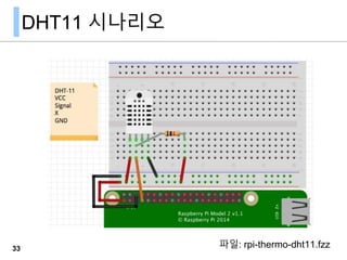
- 28. DHT11 시나리오 33 파일: rpi-thermo-dht11.fzz
- 29. DHT11 라이브러리 DHT11 라이브러리 - https://github.com/szazo/DHT11_Python 새로운 dht11 작업 폴더를 만들고 라이브러리를 다운로드한다. $mkdir dht11python && cd dht11python $wget https://github.com/szazo/DHT11_Python/raw/master/dht11.py $vi dht11python.py 35
- 30. dht11python.py import RPi.GPIO as GPIO import dht11 # initialize GPIO GPIO.setwarnings(False) GPIO.setmode(GPIO.BCM) GPIO.cleanup() instance = dht11.DHT11(pin = 4) result = instance.read() if result.is_valid(): print("Temperature: %d C" % result.temperature) print("Humidity: %d %%" % result.humidity) else: print("Error: %d" % result.error_code) 36 Wikidocs에서 파이썬 모듈 부 분을 다시한번 본다
- 32. dht11python.py git clone https://github.com/adafruit/Adafruit_Python_DHT.git cd Adafruit_Python_DHT sudo python setup.py install #!/usr/bin/python import sys import Adafruit_DHT humidity, temperature = Adafruit_DHT.read_retry(11, 4) if humidity is not None and temperature is not None: print 'Temp={0:0.1f}*C Humidity={1:0.1f}%'.format(temperature, humidity) else: print 'Failed to get reading. Try again!' 38 시스템 개발 라이브러리가 설치되어 있어야 한다. sudo apt-get update sudo apt-get install build-essential python-dev Wikidocs에서 파이썬 모듈 부분을 다시한번 본다
- 33. HC-SR04
- 34. HC-SR04 초음파 센서 HC-SR04 모듈은 초음파를 보내서 반사되는 시간 을 측정하여 거리를 계산한 결과를 제공 https://goo.gl/R1yVKG40 VCC Trig Echo GND HC-SR04
- 35. 동작 원리 - triger 핀에 10us 정도의 High 신호를 주면 초음파센서는 40khz 펄스를 자동적으로 8번을 발생 - 펄스를 발생시킨 직후에 echo 핀은 high 되고 반사된 초음파 가 감지 되었을때 echo 핀이 low 가 된다. - echo 핀이 high였다가 low가 (Ton)되는데 걸리는 시간( 폭)을 측정 41 HC-SR04
- 36. 시간,거리 계산 Trig 핀에서 요청후 Echo 핀 응답 시간을 이용해 거리를 계산. 소리의 속도는 343m/s, Trig 후 Echo 시간이 걸리므로 다음 식; 42 HC-SR04
- 37. Fritzing HC-SR04 part Fritzing HC-SR04 를 다음 링크에서 다운로드 - https://code.google.com/p/fritzing/issues/detail?id=2637 다운로드한 파일을 더블클릭해 Fritzing으로 가져오기를 한다. Fritzing의 Mine에 새로운 부품이 놓여진다. 43 HC-SR04
- 39. gpio-hc-sr04.py import RPi.GPIO as GPIO import time TRIG = 23 ECHO = 24 GPIO.setmode(GPIO.BCM) print("Distance Measurement In Progress") GPIO.setup(TRIG,GPIO.OUT) GPIO.setup(ECHO,GPIO.IN) GPIO.output(TRIG, False) print("Waiting For Sensor To Settle") time.sleep(2) # 계속... 45 HC-SR04
- 40. gpio-hc-sr04.py # 이어서... GPIO.output(TRIG, True) time.sleep(0.00001) GPIO.output(TRIG, False) while GPIO.input(ECHO)==0: pulse_start = time.time() while GPIO.input(ECHO)==1: pulse_end = time.time() pulse_duration = pulse_end - pulse_start distance = pulse_duration x 17150 distance = round(distance, 2) print( "Distance:",distance,"cm") GPIO.cleanup() 46 HC-SR04 2~5초 사이에 한번씩 거리 측정 값을 출력하게 변경해 보자
Editor's Notes
- #29: https://sourceforge.net/p/raspberry-gpio-python/wiki/PWM/
- #43: https://www.modmypi.com/blog/hc-sr04-ultrasonic-range-sensor-on-the-raspberry-pi
- #45: https://www.modmypi.com/blog/hc-sr04-ultrasonic-range-sensor-on-the-raspberry-pi
- #46: https://www.modmypi.com/blog/hc-sr04-ultrasonic-range-sensor-on-the-raspberry-pi
- #47: https://www.modmypi.com/blog/hc-sr04-ultrasonic-range-sensor-on-the-raspberry-pi