SlideShare a Scribd company logo
CONTENTS:
1.1. Challenges for wireless sensor networks
1.2. Characteristics requirements-required mechanisms,
1.3. Difference between mobile ad-hoc and sensor networks,
1.4. Applications of sensor networks-
1.5 Enabling technologies for wireless sensor networks
UNIT-I
OUTCOMES:
To understand network architecture, node discovery and localization, deployment strategies, fault
tolerant and network security
UNIT-I
OUTCOMES:
To understand network architecture, node discovery and localization, deployment strategies, fault
tolerant and network security
•Wireless sensor networks combine sensing, processing and networking over miniaturized
embedded devices → sensor nodes.
Wireless sensor networks are networks that consists of sensors which are distributed in an ad
hoc manner. These sensors work with each other to sense some physical phenomenon and then
the information gathered is processed to get relevant results.
Wireless sensor networks consists of protocols and algorithms with self-organizing capabilities.
1.1. Challenges for wireless sensor networks
INTRODUCTION:
Wireless sensor networks
(WSNs) have been considered as
one of the most important
technologies that are enabled by
recent advances in –
Micro-electronic-mechanical-
systems(MEMS) Wireless
Communication technologies.
.
Introduction
Infrastructure Based Wireless Network
Typical Wireless Network: Based on Infrastructure -Eg: GSM , UMTS
Base stations connected to a wired backbone network
.
Introduction
Infrastructure Free Wireless Network
Military Networking: Tanks, Soldiers, etc.,
Finding out empty parking lots in a city, without asking a server
Search and Rescue in an advance
Personal Area Networking (Watch, Glasses, PDA, Medical Appliances….etc.,)
.
1.1. Challenges for wireless sensor networks
WSN can handle such a wide range of application types. Nonetheless, certain common traits
appear, especially with respect to the characteristics and the required mechanisms of such
systems.
Realizing these characteristics with new mechanisms is the major challenge of the vision of
wireless sensor networks.
Characteristic requirements : The following characteristics are shared among most of the
application examples discussed above:
1. Type of service
2. Quality of service
3. Fault tolerance
4.Lifetime
5. Scalability
6. Wide range of densities
7. Programmability
8. Maintainability
.
1.1. Challenges for wireless sensor networks
Heterogeneity
The devices deployed maybe of various types and need to collaborate with each other.
Distributed Processing
The algorithms need to be centralized as the processing is carried out on different
nodes.
Low Bandwidth Communication
The data should be transferred efficiently between sensors
Large Scale Coordination
The sensors need to coordinate with each other to produce required results
Utilization of Sensors
The sensors should be utilized in a ways that produce the maximum performance and use less
energy.
Real Time Computation
The computation should be done quickly as new data is always being generated.
.
1.1. Challenges for wireless sensor networks
 Energy Efficiency
 Limited storage and computation
 Low bandwidth and high error rates
 Errors are common
-Wireless communication
-Noisy measurements
-Node failure are expected
Scalability to a large number of sensor nodes
Survivability in harsh environments
Experiments are time- and space-intensive
.
1.2. Characteristics requirements-required mechanisms
Required mechanisms
To realize these requirements, innovative mechanisms for a communication network have to be
found, as well as new architectures, and protocol concepts.
A particular challenge here is the need to find mechanisms that are sufficiently specific to the
idiosyncrasies of a given application to support the specific quality of service, lifetime, and
maintainability requirements.
Some of the mechanisms that will form typical parts of WSNs are:
Multi-hop wireless communication
Energy-efficient operation
Auto-configuration
Collaboration and in-network processing
Data centric
Locality
Exploit trade-offs
.
1.2. Characteristics requirements-required mechanisms
Conventional Networks WSN
General purpose design (many
applications)
Serving a single application or a bouquet of
applications
Network Performance and Latency Energy is the primary challenge
Devices and networks operate in controlled
/ mild environments (or over an
appropriate infrastructure)
Unattended, harsh conditions & hostile
environments
Easily accessible Physical access is difficult / undesirable
Global knowledge is feasible and
centralized management is possible
Localized decisions – no support by central entity
Differences between Conventional and Wireless sensor networks
.
1.3 . Difference between mobile ad-hoc and sensor networks
An ad hoc network is a network that is setup, for a specific purpose, to meet a quickly appearing
communication need.
The simplest example of an ad hoc network is perhaps a set of computers connected together via
cables to form a small network, like a few laptops in a meeting room. In this example, the aspect of
self- configuration is crucial – the network is expected to work without manual management or
configuration.
Wireless sensor networks mainly use broadcast communication while ad hoc networks
use point-to-point communication.
Unlike ad hoc networks wireless sensor networks are limited by sensors limited power,
energy and computational capability.
Sensor nodes may not have global ID because of the large amount of overhead and large
number of sensors.
.
1.3 . Difference between mobile ad-hoc and sensor networks
Key characteristic that distinguishes them from remaining networks is the
reasoning of existence:
Collect information from the physical environment – regardless of
how easily accessible that is;
Couple the end-users directly to the sensor measurements ( cyber to physical space);
Provide information that is precisely localized (in spatio-temporal
terms) according to the application demands;
Establish a bi-directional link with the physical space (remote & adaptable actuation
based on the sensing stimulus)
.
1.4. Applications of sensor networks
Examples of Wireless sensor Networks
.
1.4. Applications of sensor networks
The applications can be divided in three categories:
1. Monitoring of objects.
2. Monitoring of an area.
3. Monitoring of both area and objects.
Monitoring Area:
1. Environmental and Habitat Monitoring
2. Precision Agriculture
3. Indoor Climate Control
4. Military Surveillance
5. Treaty Verification
6. Intelligent Alarms
.
1.4. Applications of sensor networks
• Precision agriculture aims at making
cultural operations more efficient,
while reducing environmental
impact.
• The information collected from
sensors is used to evaluate optimum
sowing density, estimate fertilizers
and other inputs needs, and to more
accurately predict crop yields.
. Monitoring objects:
1.4. Applications of sensor networks
Structural Monitoring
Eco-physiology
Condition-based Maintenance
Medical Diagnostics
Urban terrain mapping
Example: Condition-based Maintenance: Intel fabrication plants
Sensors collect vibration data, monitor wear and tear; report data in real-time
Reduces need for a team of engineers; cutting costs by several orders of magnitude
.
1.4. Applications of sensor networks
Monitoring Interactions between Objects and Space
Wildlife Habitats
Disaster Management
Emergency Response
Ubiquitous Computing
Asset Tracking
Health Care
Manufacturing Process Flows
.
1.4. Applications of sensor networks
The Zebra-Net Project
Collar-mounted sensors monitor zebra movement
in Kenya
.
1.4. Applications of sensor networks
Future of WSN: Smart Home / Smart Office
Sensors controlling appliances and
electrical devices in the house.
Better lighting and heating in office
buildings.
The Pentagon building has used
sensors extensively.
.
1.5 Enabling technologies for wireless sensor networks
Exploit spatially and temporally dense, in situ, sensing and actuation
Building such wireless sensor
networks has only become
possible with some fundamental
advances in enabling
technologies.
•Miniaturization of hardware
•Energy Scavenging
Cost
MEMS’ is a key technology for manufacturing tiny, low - cost, and low – power sensor
nodes. By integrating different components together into a single process, the size of a
sensor node can significantly be reduced.
.
1.5 Enabling technologies for wireless sensor networks
Smaller feature sizes in chips have driven down the power consumption of the basic
components of a sensor node - like microcontrollers, memory chips, radio modems, etc.; have
become much more energy efficient.
Reduced chip size and improved energy efficiency is accompanied by reduced cost, which is
necessary to make redundant deployment of nodes affordable.
Next to processing and communication, the actual sensing equipment is the third relevant
technology.
These three basic parts of a sensor node have to accompany by power supply. This requires,
depending on application, high capacity batteries that last for long times, that is, have only a
negligible self-discharge rate, and that can efficiently provide small amounts of current.
.
1.5 Enabling technologies for wireless sensor networks
To achieve low - power consumption at the node level, it is necessary to incorporate power
awareness and energy optimization in hardware design for sensor networks.
Power consumption can further be reduced through efficiently operating various system
resources using some dynamic power management (DPM) technique
•Ideally, a sensor node also has a device for energy scavenging, recharging the battery
with energy gathered from the environment – solar cells or vibration-based power
generation are conceivable options.
Such a concept requires the battery to be efficiently chargeable with small amounts of
current, which is not a standard ability
1. Discuss challenges and hurdles for wireless sensor networks.
2. Explain the historical background of sensor networks.
3. Various applications of wireless sensor networks.
4. Explain Industrial Automation
5. Discuss about Home Automation
Assignment Question
Sensor node Architectures
A Wireless Sensor Network is one kind of wireless network includes a large number
of circulating, self-directed, minute, low powered devices named sensor nodes
called motes.
These networks certainly cover a huge number of spatially distributed, little,
battery-operated, embedded devices that are networked to caringly collect, process,
and transfer data to the operators, and it has controlled the capabilities of
computing & processing. Nodes are the tiny computers, which work jointly to form
the networks.
Contents:
2.1. Single-node architecture - hardware components,
2.2. Energy consumption of sensor nodes,
2.3. Operating systems and Execution environments
2.4. Network architecture - sensor network scenarios,
2.5. Optimization goals and figures of merit, gateway concepts.
Architectures
2.1. Single-node architecture - hardware components
.
•Controller A controller to
process all the relevant data,
capable of executing arbitrary
code.
•Memory Some memory to store
programs and intermediate data;
usually, different types of
memory are used for programs
and data.
•Sensors and actuators The actual interface to the physical world: devices that can observe or
control physical parameters of the environment.
• Communication Turning nodes into a network requires a device for sending and receiving
information over a wireless channel
.
2.1. Single-node architecture - hardware components
•The sensor node is a multi-functional, energy efficient wireless device. The applications of motes
in industrial are widespread.
•A collection of sensor nodes collects the data from the surroundings to achieve specific
application objectives.
•The communication between motes can be done with each other using transceivers. In a
wireless sensor network, the number of motes can be in the order of hundreds/ even thousands.
• In contrast with sensor networks, Ad Hoc networks will have fewer nodes without any
structure.
Power supply As usually no tethered power supply is available, some forms of batteries are
necessary to provide energy. Sometimes, some form of recharging by obtaining energy from the
environment is available as well (e.g. solar cells).
Each of these components has to operate balancing the trade-off between as small an energy
consumption as possible on the one hand and the need to ful-fil their tasks on the other hand.
For example, both the communication device and the controller should be turned off as long as
possible.
2.1. Single-node architecture - hardware components
Hardware Components:
Power supply
 Microcontrollers vs Microprocessors, FPGAs and ASIC
 Memory
 Communication devices
 Sensors & Actuators
- Passive omni- directional sensors
- Passive narrow- beam sensors
- Active sensors
- Actuators
Memory
The memory component is fairly straightforward. Evidently, there is a need for Random Access
Memory (RAM) to store intermediate sensor readings, packets from other nodes, and so on.
While RAM is fast, its main disadvantage is that it loses its content if power supply is interrupted.
Program code can be stored in Read-Only Memory (ROM) or, more typically, in Electrically Erasable
Programmable Read-Only Memory (EEPROM) or flash memory (the later being similar to EEPROM
but allowing data to be erased or written in blocks instead of only a byte at a time).
2.1. Single-node architecture - hardware components
Communication device:
Choice of transmission medium
The communication device is used to exchange data between individual nodes. In some cases,
wired communication can actually be the method of choice and is frequently applied in many
sensor Network like settings (using field buses like Profi-bus, LON, CAN, or others).
The communication devices for these networks are custom off-the-shelf components.
Transceivers
For actual communication, both a transmitter and a receiver are required in a sensor node. The
essential task is to convert a bit stream coming from a microcontroller (or a sequence of bytes or
frames) and convert them to and from radio waves.
 For practical purposes, it is usually convenient to use a device that combines these two tasks in
a single entity. Such combined devices are called transceivers.
Usually, half-duplex operation is realized since transmitting and receiving at the same time on a
wireless medium is impractical in most cases (the receiver would only hear the own transmitter
anyway).
.
2.1. Single-node architecture - hardware components
Transceiver tasks and characteristics
To select appropriate transceivers, a number of characteristics should be taken into account.
The most important ones are:
Service to upper layer
Power consumption and energy efficiency
Carrier frequency and multiple channels
State change times and energy
Data rates
Modulations
Coding
Noise figure The noise figure
Gain
Power efficiency
Receiver sensitivity
Range
Blocking performance
Out of band emission
Carrier sense and RSSI
Frequency stability and Voltage range
.
2.1. Single-node architecture - hardware components
A fairly common structure of transceivers is
into the Radio Frequency (RF) front end and
the baseband part:
• The radio frequency front end performs
analog signal processing in the actual radio
frequency band, whereas
• The baseband processor performs all signal processing in the digital domain and
communicates with a sensor node’s processor or other digital circuitry.
. Transceiver operational states:
many transceivers can distinguish four operational states :
Transmit in the transmit state, the transmit part of the transceiver is active and the antenna radiates
energy.
Receive in the receive state the receive part is active.
2.1. Single-node architecture - hardware components
Idle A transceiver that is ready to receive but is not currently receiving anything is said to be in an
idle state.
Sleep In the sleep state, significant parts of the transceiver are switched off.
There are transceivers offering several different sleep states, see reference for a discussion of
sleep states for IEEE 802.11 transceivers. These sleep states differ in the amount of circuitry
switched off and in the associated recovery times and startup energy
.
2.1. Single-node architecture - hardware components
Sensors and actuators
Without the actual sensors and actuators, a wireless sensor network would be beside the point
entirely.
But as the discussion of possible application areas has already indicated, the possible range of
sensors is vast.
It is only possible to give a rough idea on which sensors and actuators can be used in a WSN
Sensors
Sensors can be roughly categorized into three categories
Passive, omni-directional sensors
Passive, narrow-beam sensors
Active sensors
.
2.1. Single-node architecture - hardware components
Power supply of sensor nodes
For untethered wireless sensor nodes, the power supply is a crucial system
component. There are essentially two aspects: First, storing energy and providing
power in the required form;
second, attempting to replenish consumed energy by “scavenging” it from some node-
external power source over time.
Storing power is conventionally done using batteries. As a rough orientation, a normal
AA battery stores about 2.2–2.5 Ah at 1.5 V.
Storing energy: Batteries
Traditional batteries
Capacity
Capacity under load
Self-discharge
Efficient recharging, Relaxation, Unconventional energy stores and DC–DC Conversion
.
2.1. Single-node architecture - hardware components
Energy scavenging
Some of the unconventional energy
stores described above – fuel cells, micro
heat engines, radioactivity
– convert energy from some stored,
secondary form into electricity in a less
direct and easy to use way than a normal
battery would do. The entire energy
supply is stored on the node itself – once
the fuel supply is exhausted, the node
fails.
To ensure truly long-lasting nodes and
wireless sensor networks, such a limited
energy store is unacceptable. Rather,
energy from a node’s environment must
be tapped into and made available
to the node – energy scavenging
should take place.
A MEMS device for converting vibrations to electrical
energy, based on a variable capacitor .Reproduced by
permission of IEEE
.
2.2 Energy Consumption of Sensor Nodes
At time t1, the decision whether or
not a component (say, the
microcontroller) is to be put into
sleep mode should be taken to
reduce power consumption from
Pactive to Psleep.
If it remains active and the next
event occurs at time tevent, then
a total energy of Eactive =
Pactive(tevent − t1) has be spent
uselessly idling.
Putting the component into sleep mode, on the other hand, requires a time τdown until sleep mode
has been reached; as a simplification, assume that the average power consumption during this phase
is (Pactive + Psleep)/2.
Then, Psleep is consumed until tevent. In total, τdown(Pactive + Psleep)/2 + (tevent − t1 −
τdown)Psleep energy is required in sleep mode as opposed to (tevent − t1)Pactive when remaining
active.
.
2.2 Energy Consumption of Sensor Nodes
Microcontroller energy consumption
Basic power consumption in discrete operation
states:
Intel Strong ARM
The Intel Strong ARM ,In normal mode, all parts of
the processor are fully powered.
Power consumption is up to 400 mW.
• In idle mode, clocks to the CPU are stopped; clocks that pertain to peripherals are active. Any
interrupt will cause return to normal mode. Power consumption is up to 100 mW.
• In sleep mode, only the real-time clock remains active. Wakeup occurs after a timer interrupt and
takes up to 160 ms. Power consumption is up to 50 μW.
Energy per operation with dynamic power scaling on an Intel
Strong ARM SA-1100
2.3 Operating systems and Execution Environments
1. Embedded operating systems: The
traditional tasks of an operating system
are controlling and protecting the access
to resources (including support for
input/output) and managing their
allocation to different users as well as the
support for concurrent execution of
several processes and communication
between these processes.
2. 2.Programming paradigms and
application programming interfaces
(concurrent programming):
- Process-based concurrency
- Event- based programming
- Interfaces to the operating
systems
.
2.3 Operating systems and Execution Environments
Event based programming
model:
Such an event handler can interrupt
the processing of any normal code, but
as it is very simple and short, it can be
required to run to completion in all
circumstances without noticeably
disturbing other code
Event handlers cannot interrupt each other (as this would in turn require complicated stack
handling procedures) but are simply executed one after each other.
CONTENTS:
2.4. Network architecture - sensor network scenarios,
2.5. Optimization goals and figures of merit, gateway concepts
OUTCOMES:
Unit 2:Network Architecture
To Discuss About network architecture and optimization goals with the figure of Merit Concepts
.
2.4. Network architecture - sensor network scenarios
Three types of sinks in a very simple single-hop sensor network
Types of Sources and sinks:
-Single hop versus Multi hop
From the basics of radio communication and the inherent power limitation of radio communication
follows a limitation on the feasible distance between a sender and a receiver. Because of this
limited distance, the simple, direct communication between source and sink is not always possible,
specifically in WSNs, which are intended to cover a lot of ground (e.g. in environmental or
agriculture applications) or that operate in difficult radio environments with strong attenuation
.Multi hop network:
2.4. Network architecture - sensor network scenarios
To overcome such limited distances, an obvious
way out is to use relay stations, with the data
packets taking multi hops from the source to the
sink.
This concept of multi-hop networks is
particularly attractive for WSNs as the sensor
nodes themselves can act as such relay nodes,
foregoing the need for additional equipment
Depending on the particular application, the likelihood of having an intermediate sensor node at
the right place can actually be quite high
.
2.4. Network architecture - sensor network scenarios
Multiple sources and/or multiple sinks
In many cases, there are multiple sources and/or multiple sinks present. In the most challenging
case, multiple sources should send information to multiple sinks, where either all or some of the
information has to reach all or some of the sinks. Figure illustrates these combinations.
.
2.4. Network architecture - sensor network scenarios
Three types of
Mobility
 Node mobility
 Sink mobility
 Event mobility
Communication protocols
for WSNs will have to
render appropriate
support for these forms of
mobility.
In particular, event
mobility is quite
uncommon, compared to
previous forms of mobile
or wireless networks.
A mobile sinks moves through a mobile sensor network as a
information being retrieves on its behalf
.
2.5. Optimization goals and figures of merit, gateway concepts
For all these scenarios and application types, different forms of networking solutions can be found.
The challenging question is how to optimize a network, how to compare these solutions, how to
decide which approach better supports a given application, and how to turn relatively imprecise
optimizing goals into measurable figures of merit? While a general answer appears impossible
considering the large variety of possible applications, a few aspects are fairly evident
1. Quality of service
- Event detection/reporting probability
- Event classification error
- Event detection delay
- Missing reports
- Approximation accuracy
- Tracking accuracy
2. Energy efficiency
- Energy/correctly received
- Energy/reported event
- Delay
- N/w Life time
3. Scalability
4. Robustness
Area of sensor nodes detecting an event-an elephant-that moves through the network along
with the event source
2.5. Optimization goals and figures of merit, gateway concepts
Need for Gate ways
For practical deployment, a sensor network only concerned with itself is insufficient. The network
rather has to be able to interact with other information devices,
for example, a user equipped with a PDA moving in the coverage area of the network or with a
remote user, trying to interact with the sensor network via the Internet (the standard example is to
read the temperature sensors in one’s home while traveling and accessing the Internet via a
wireless connection). Figure shows this networking scenario.
.
2.5. Optimization goals and figures of merit, gateway concepts
1. WSN to Internet communication
A sensor node wants to deliver an alarm
message to some Internet host.
The first problem to solve is akin to ad
hoc networks, namely, how to find the
gateway from within the network.
Basically, a routing problem to a node that offers a specific service has to be solved, integrating
routing and service discovery
.
2.5. Optimization goals and figures of merit, gateway concepts
2. Internet to WSN communication
The case of an Internet-based entity trying
to access services of a WSN is even more
challenging .
This is fairly simple if this requesting
terminal is able to directly communicate
with the WSN, for example, a mobile
requester equipped with a WSN transceiver,
and also has all the necessary protocol
components at its disposal
In this case, the requesting terminal can be a direct part of the WSN and no particular treatment is
necessary
.
2.5. Optimization goals and figures of merit, gateway concepts
3. WSN tunneling
In addition to these scenarios describing
actual interactions between a WSN and
Internet terminals, the gateways can also
act as simple extensions of one WSN to
another WSN.
The idea is to build a larger, “virtual” WSN
out of separate parts, transparently
“tunneling” all protocol messages between
these two networks and simply using the
Internet as a transport network.
This can be attractive, but care has to be taken not to confuse the virtual link between two gateway
nodes with a real link; otherwise, protocols that rely on physical properties of a communication
link can get quite confused.
.
Assignment Question
1. Write short notes on Berkeley Motes.
2. Explain single node architecture.
3. Explain Gateway concepts.
4. Explain network architecture and sensor network scenarios.
5. What is the function of controller in sensor node architecture.
INTRODUCTION:
The physical layer is mostly concerned with modulation and demodulation of digital data; this task
is carried out by so-called transceivers. In sensor networks, the challenge is to find modulation
schemes and transceiver architectures that are simple, low cost, but still robust enough to provide
the desired service.
Medium Access Control (MAC) protocols is the first protocol layer above the Physical Layer (PHY)
and consequently MAC protocols are heavily influenced by its properties. The fundamental task of
any MAC protocol is to regulate the access of a number of nodes to a shared medium in such a way
that certain application-dependent performance requirements are satisfied.
UNIT-III: Physical Layer and MAC Protocols
Contents:
3.1. physical layer and transceiver design considerations,
3.2. MAC protocols for wireless sensor networks,
3.3. Low duty cycle protocols and wakeup concepts - S-MAC,
- Zigbee: IEEE 802.15.4 MAC layer,
- the mediation device protocol,
- wakeup radio concepts,
3.4. Address and name management,
3.5. Assignment of MAC addresses,
3.6. Routing protocols
- Energy-efficient routing,
- Geographic routing.
UNIT-III: Physical Layer and MAC Protocols
In sensor networks, the challenge is to find modulation schemes and transceiver architectures that
are simple, low cost, but still robust enough to provide the desired service.
Wireless channel and communication fundamentals:
1. Frequency allocation
2. Modulation and demodulation
3. Wave propagation effects and noise
- Reflection, diffraction, scattering, doppler fading
- Path loss and attenuation
- Noise and interference
- Symbols and bit errors
4. Channel models
5. Spread-spectrum communications
- Direct Sequence Spread Spectrum (DSSS) and
- Frequency Hopping Spread Spectrum (FHSS)
6. Packet transmission and synchronization
- Carrier synchronization
- Bit/symbol synchronization
- Frame synchronization
INTRODUCTION
Introduction: For actual communication, both a transmitter and a receiver are required in a sensor
node. The essential task is to convert a bit stream coming from a and convert them to and from radio
waves. For practical purposes, it is usually convenient to use a device that combines these two tasks
in a single entity. Such combined devices are called “transceivers”
3.1. Physical Layer and Transceiver Design Considerations
Some of the most crucial points influencing PHY design in wireless sensor networks are:
• Low power consumption.
• As one consequence: small transmit power and thus a small transmission range.
• As a further consequence: low duty cycle. Most hardware should be switched off or operated in
a low-power standby mode most of the time.
• Comparably low data rates, on the order of tens to hundreds kilobits per second, required.
• Low implementation complexity and costs.
• Low degree of mobility.
• A small form factor for the overall node
In general, in sensor networks, the challenge is to find modulation schemes and transceiver
architectures that are simple, low-cost but still robust enough to provide the desired service.
3.1. Physical Layer and Transceiver Design Considerations
1. Energy usage profile:
The choice of a small transmit power leads to an energy consumption profile different from
other wireless devices like cell phones.
The radiated energy is small, typically on the order of 0 dBm (corresponding to 1mW). On
the other hand, the overall transceiver (RF front end and baseband part) consumes much
more energy than is actually radiated.
A second key observation is that for small transmit powers the transmit and receive modes
consume more or less the same power; it is even possible that reception requires more
power than transmission.
A third key observation is the relative costs of communications versus computation in a
sensor node. Clearly, a comparison of these costs depends for the communication part on the
BER requirements, range, transceiver type, and so forth, and for the computation part on the
processor type, the instruction mix, and so on.
2. Choice of modulation scheme:
A crucial point is the choice of modulation scheme. Several factors have to be balanced
here: the required and desirable data rate and symbol rate, the implementation
complexity, the relationship between radiated power and target BER, and the expected
channel characteristics.
Table: Bandwidth efficiency ηBW and Eb/N0[dB] required at the receiver to reach a BER of 10−6 over an AWGN channel
for m-ary orthogonal FSK and PSK
3.1. Physical Layer and Transceiver Design Considerations
3. Dynamic modulation scaling
To determine the optimal scheme for a given combination of BER target, range, packet sizes and so
forth, such an optimum is only valid for short time; as soon as one of the constraints changes, the
optimum can change, too.
In addition, other constraints like delay or the desire to achieve high throughput can dictate to
choose higher modulation schemes.
Therefore, it is interesting to consider methods to adapt the modulation scheme to the current
situation. Such an approach, called dynamic modulation scaling.
4. Antenna considerations
If the antenna is much smaller than the carrier’s wavelength, it is hard to achieve good antenna
efficiency, that is, with ill-sized antennas one must spend more transmit energy to obtain the same
radiated energy.
with small sensor node cases, it will be hard to place two antennas with suitable distance to achieve
receive diversity
3.1. Physical Layer and Transceiver Design Considerations
Medium access control (MAC) protocols solve a seemingly simple task: they coordinate
the times where a number of nodes access a shared communication medium
an “un-overseeable” number of protocols have emerged in more than thirty years of
research in this area. They differ, among others, in the types of media they use and in the
performance requirements for which they are optimized.
Medium Access Control (MAC) protocols is the first protocol layer above the Physical
Layer (PHY) and consequently MAC protocols are heavily influenced by its properties.
The fundamental task of any MAC protocol is to regulate the access of a number of nodes
to a shared medium in such a way that certain application-dependent performance
requirements are satisfied
3.2. MAC PROTOCOLS for WSN
The most important performance requirements for MAC protocols are throughput ,
efficiency,
stability,
fairness,
low access delay and
low transmission delay
as well as a low overhead
The overhead in MAC protocols can result from per-packet overhead (MAC headers and trailers),
collisions, or from exchange of extra control packets.
 Collisions can happen if the MAC protocol allows two or more nodes to send packets at the same
time. Collisions can result in the inability of the receiver to decode a packet correctly, causing the
upper layers to perform a retransmission.
For time-critical applications, it is important to provide deterministic or stochastic guarantees on
delivery time or minimal available data rate.
Sometimes, preferred treatment of important packets over unimportant ones is required, leading
to the concept of priorities
3.2.Requirements and design constraints for wireless MAC protocols
1. Hidden Terminal Problem
2. Exposed terminal scenario
we have three nodes A, B, and C that are arranged such that A and B are in mutual range, B and
C are in mutual range, but A and C cannot hear each other. Assume that A starts to transmit a
packet to B and some time later node C also decides to start a packet transmission. A carrier-
sensing operation by C shows an idle medium since C cannot hear A’s signals. When C starts its
packet, the signals collide at B and both packets are useless.
Important classes of MAC protocols:
1.Fixed assignment protocols
-TDMA, FDMA, CDMA, and SDMA.
2.Demand assignment protocols
-HIPERLAN/2 protocol
-DQRUMA
-MASCARA protocol
-polling schemes
3. Random access protocols
-CSMA protocols
-non-persistent CSMA
-persistent CSMA
3.2.Requirements and design constraints for wireless MAC protocols
The RTS/CTS handshake as used in IEEE 802.11 is based on the MACAW protocol
and it uses only a single channel and two special control packets.
3.2.Requirements and design constraints for wireless MAC protocols
RTS/CTS handshake
in IEEE 802.11
Further problem of the RTS/CTS handshake is its significant overhead of two control packets per
data packet, not counting the acknowledgment packet. If the data packet is small, this overhead
might not pay off and it may be simpler to use some plain CSMA variant
3.2 Requirements and Design constraints for wireless MAC
Two problems in
RTS/CTS Handshake
3.2 MAC Protocols for WSN
Balance of requirements
Energy problems on the MAC layer
-Collisions
-Overhearing
-Protocol overhead
-Idle listening
Structure
-contention-based
-schedule-based protocols
Balance of requirements:
3.2 MAC Protocols for WSN
The balance of requirements is different from traditional (wireless) networks.
Additional requirements come up, first and foremost, the need to conserve energy.
The importance of energy efficiency for the design of MAC protocols is relatively new
and many of the “classical” protocols like ALOHA and CSMA contain no provisions
toward this goal.
 Other typical performance figures like fairness, throughput, or delay tend to play a
minor role in sensor networks.
Fairness is not important since the nodes in a WSN do not represent individuals
competing for bandwidth, but they collaborate to achieve a common goal.
The access/transmission delay performance is traded against energy
conservation, and throughput is mostly not an issue either.
3.2 MAC Protocols for WSN
Energy problems on the MAC layer
Further important requirements for MAC protocols are scalability and robustness
against frequent topology changes, as caused for example by nodes powering down
temporarily to replenish their batteries by energy scavenging, mobility, deployment of
new nodes, or death of existing nodes.
The need for scalability is evident when considering very dense sensor networks with
dozens or hundreds of nodes in mutual range.
Nodes transceiver consumes a significant share of energy.
Transceiver can be in one of the four main states : transmitting, receiving, idling, or
sleeping.
Transmitting is costly, receive costs often have the same order of magnitude as
transmit costs, idling can be significantly cheaper but also about as expensive as
receiving, and sleeping costs almost nothing but results in a “deaf” node.
3.2 MAC Protocols for WSN
Collisions :
Collisions incur useless receive costs at the destination node, useless transmit costs
at the source node, and the prospect to expend further energy upon packet
retransmission.
Hence, collisions should be avoided, either by design (fixed assignment/TDMA or
demand assignment protocols) or by appropriate collision avoidance/hidden-
terminal procedures in CSMA protocols.
Overhearing :
 Uni-cast frames have one source and one destination node.
 However, the wireless medium is a broadcast medium and all the source’s neighbors
that are in receive state hear a packet and drop it when it is not destined to them; these
nodes overhear the packet.
 For higher node densities overhearing avoidance can save significant amounts of
energy. On the other hand, overhearing is sometimes desirable.
3.2 MAC Protocols for WSN
Protocol overhead :
 Protocol overhead is induced by MAC-related control frames like, for example,
RTS and CTS packets or request packets in demand assignment protocols, and
furthermore by per-packet overhead like packet headers and trailers.
Idle listening:
A node being in idle state is ready to receive a packet but is not currently receiving
anything.
This readiness is costly and useless in case of low network loads; for many radio
modems, the idle state still consumes significant energy.
Switching off the transceiver is a solution; however, since mode changes also cost
energy, their frequency should be kept at “reasonable” levels.
3.2 MAC Protocols for WSN
Some other protocols are classified into either contention-based or schedule-
based protocols.
This distinction is to be understood by the number of possible contenders upon a
transmit opportunity towards a receiver node:
 In contention-based protocols , any of the receiver’s neighbors might try its luck
at the risk of collisions.
Accordingly, those protocols contain mechanisms to avoid collisions or to reduce
their probability.
In schedule-based protocols ,only one neighbor gets an opportunity and collisions
are avoided. These protocols have a TDMA component, which provides also an
implicit idle listening avoidance mechanism: when a node knows its allocated slots
and can be sure that it communicates (transmits/receives) only in these slots, it can
safely switch off its receiver at all other times
.
3.3. Low duty cycle protocols and wakeup concepts
Low duty cycle
protocols try to avoid
spending (much) time
in the idle state and to
reduce the
communication
activities of a sensor
node to a minimum.
In an ideal case, the sleep state is left only when a node is about to transmit or receive
packets. To achieve this WAKEUP RADIO Concept is introduced.
In several protocols, a periodic wakeup scheme is used. Such schemes exist in
different flavors.
This approach, nodes spend most of their time in the sleep mode and wake up periodically
to receive packets from other nodes. Specifically, a node A listens onto the channel during
its listen period and goes back into sleep mode when no other node takes the
opportunity to direct a packet to A.
• .
3.3. Low duty cycle protocols and wakeup concepts
By choosing a small duty cycle, the transceiver is in sleep mode most of the time,
avoiding idle listening and conserving energy.
• By choosing a small duty cycle, the traffic directed from neighboring nodes to a
given node concentrates on a small time window (the listen period) and in heavy
load situations significant competition can occur.
• Choosing a long sleep period induces a significant per-hop latency, since a
prospective transmitter node has to wait an average of half a sleep period before
the receiver can accept packets. In the multi-hop case, the per-hop latencies add up
and create significant end-to-end latencies.
• Sleep phases should not be too short lest the start-up costs outweigh the benefits
There is also a periodic wakeup but nodes can both transmit and receive during their
wakeup phases. When nodes have their wakeup phases at the same time, there is no
necessity for a node wanting to transmit a packet to be awake outside these phases to
rendezvous its receiver.
.
3.2 Sparse topology and energy management (STEM)
The Sparse Topology and Energy Management (STEM) protocol does not cover all
aspects of a MAC protocol but provides a solution for the idle listening problem
STEM duty cycle for a single node
STEM targets networks that are deployed to wait for and report on the behavior of a
certain event.
The S-MAC (Sensor-MAC) protocol provides mechanisms to circumvent idle
listening, collisions, and overhearing. As opposed to STEM, it does not require two
different channels.
S-MAC (Sensor –MAC)
S-MAC principle
.
S-MAC (Sensor –MAC)
S-MAC adopts a periodic wakeup scheme, that is, each node alternates between a
fixed-length listen period and a fixed-length sleep period according to its schedule, as
opposed to STEM, the listen period of S-MAC can be used to receive and transmit
packets.
 S-MAC attempts to coordinate the schedules of neighboring nodes such that their
listen periods
 Start at the same time. A node x’s listen period is subdivided into three different
phases:
. • In the first phase (SYNCH phase),
• In the second phase (RTS phase),
• In the third phase (CTS phase),
S-MAC (Sensor –MAC)
S-MAC fragmentation and NAV setting
3.2 The Mediation device protocol
The mediation device protocol is compatible with the peer-to-peer
communication mode of the IEEE 802.15.4 low-rate WPAN standard. It allows each
node in a WSN to go into sleep mode periodically and to wake up only for short times
to receive packets from neighbor nodes. There is no global time reference, each node
has its own sleeping schedule, and does not take care of its neighbors sleep schedules
3.2 The Mediation device protocol
 Upon each periodic wakeup, a node transmits a short query beacon, indicating
its node address and its willingness to accept packets from other nodes. The node
stays awake for some short time following the query beacon, to open up a window
for incoming packets. If no packet is received during this window, the node goes
back into sleep mode.
 Dynamic synchronization
 Mediation device (MD)
The dynamic synchronization approach achieves this synchronization without
requiring the transmitter to be awake permanently to detect the destinations query
beacon.
To achieve this, a mediation device (MD) is used.
.
3.3 Wakeup radio concepts
 The ideal situation would be if a node were always in the receiving state when a
packet is transmitted to it, in the transmitting state when it transmits a packet, and in
the sleep state at all other times; the idle state should be avoided.
 The wakeup radio concept strives to achieve this goal by a simple, “powerless”
receiver that can trigger a main receiver if necessary
 One proposed wakeup MAC protocol assumes the presence of several parallel data
channels, separated either in frequency (FDMA) or by choosing different codes in a
CDMA schemes.
A node wishing to transmit a data packet randomly picks one of the channels and
performs a carrier sensing operation. If the channel is busy, the node makes another
random channel choice and repeats the carrier-sensing operation.
 After a certain number of unsuccessful trials, the node backs off for a random time
and starts again.
3.2 Wakeup radio concepts
If the channel is idle, the node sends a wakeup signal to the intended receiver,
indicating both the receiver identification and the channel to use.
The receiver wakes up its data transceiver, tunes to the indicated channel, and the
data packet transmission can proceed.
Afterward, the receiver can switch its data transceiver back into sleep mode. This
wakeup radio concept has the significant advantage that only the low-power wakeup
transceiver has to be switched on all the time while the much more energy consuming
data transceiver is non sleeping if and only if the node is involved in data transmissions.
 Furthermore, this scheme is naturally traffic adaptive, that is, the MAC becomes
more and more active as the traffic load increases. Periodic wakeup schemes do
not have this property.
There are also some drawbacks. First, to our knowledge, there is no real hardware
yet for such an ultralow power wakeup transceiver. Second, the range of the wakeup
radio and the data radio should be the same.
If the range of the wakeup radio is smaller than the range of the data radio, possibly
not all neighbor nodes can be woken up.
3.2 IEEE 802.15.4 MAC protocol
IEEE finalized the IEEE 802.15.4 standard in October 2003 ,the standard covers the
physical layer and the MAC layer of a low-rate Wireless Personal Area Network
(WPAN).
Zig-Bee uses the services offered by IEEE 802.15.4 and adds network construction
(star networks, peer-to-peer/ mesh networks, cluster-tree networks), security,
application services, and more.
The targeted applications for IEEE 802.15.4 are in the area of wireless sensor
networks, home automation, home networking, connecting devices to a PC,
home security, and so on.
Most of these applications require only low-to-medium bitrates (up to some few
hundreds of kbps), moderate average delays without too stringent delay guarantees,
and for certain nodes it is highly desirable to reduce the energy consumption to a
minimum.
.
3.2 IEEE 802.15.4 MAC protocol
The physical layer offers:
 Bitrates of 20 kbps (a single channel in the frequency range 868–868.6 MHz),
 40 kbps (ten channels in the range between 905 and 928 MHz) and
250 kbps (16 channels in the 2.4 GHz ISM band between 2.4 and 2.485 GHz with
5- MHz spacing between the center frequencies).
 There are a total of 27 channels available,
 But the MAC protocol uses only one of these channels at a time;
 It is not a multichannel protocol.
 The MAC protocol combines both schedule-based as well as contention-based
schemes
. IEEE 802.15.4 MAC Protocol:
Network architecture and types/roles of nodes:
3.2 IEEE 802.15.4 MAC protocol
The standard distinguishes on the MAC layer two types of nodes:
• A Full Function Device (FFD) can operate in three different roles: it can be a PAN
coordinator (PAN = Personal Area Network), a simple coordinator or a device.
• A Reduced Function Device (RFD) can operate only as a device.
Network architecture and types/roles of nodes
Super-frame structure
GTS management
Data transfer procedures
Slotted CSMA-CA protocol
Non-beaconed mode
3.2 IEEE 802.15.4 MAC protocol
1.Network architecture and types/roles of nodes:
A device must be associated to a coordinator node (which must be a FFD) and
communicates only with this, this way forming a star network. Coordinators can
operate in a peer-to-peer fashion and multiple coordinators can form a Personal
Area Network (PAN).
The PAN is identified by a 16-bit PAN Identifier and one of its coordinators is
designated as a PAN coordinator.
A coordinator handles among others the following tasks:
It manages a list of associated devices.
It allocates short addresses to its devices.
In the beaconed mode of IEEE 802.15.4, it transmits regularly frame beacon
packets announcing the PAN identifier, a list of outstanding frames, and other
parameters.
It exchanges data packets with devices and with peer coordinators.
.
3.2 IEEE 802.15.4 MAC protocol
2. Super frame structure:
Super frame structure of IEEE 802.15.4
The coordinator of a star network operating in the beaconed mode organizes
channel access and data transmission with the help of a super frame.
All super frames have the same length. The coordinator starts each super frame by
sending a frame beacon packet.
The frame beacon includes a super frame specification describing the length of the
various components of the following super frame:
1. Active period
2. Inactive period.
The active period is subdivided into
16 time slots.
The first time slot is occupied
by the beacon frame and
the remaining time slots
1. CAP
2. GTSs
.
3.3 IEEE 802.15.4 MAC protocol
3. GTS management:
The coordinator allocates GTS to devices only when the latter send appropriate
request packets during the CAP.
One flag in the request indicates whether the requested time slot is a transmit slot
or a receive slot.
In a transmit slot, the device transmits packets to the coordinator and in a
receive slot the data flows in the reverse direction. Another field in the request
specifies the desired number of contiguous time slots in the GTS phase.
The coordinator answers the request packet in two steps: An immediate
acknowledgment packet confirms that the coordinator has received the request packet
properly but contains no information about success or failure of the request.
After receiving the acknowledgment packet, the device is required to track the
coordinator’s beacons for some specified time (called Agts DescPersistence Time).
3.3 IEEE 802.15.4 MAC protocol
4. Data transfer procedures:
Device wants to transmit a data packet to the coordinator, If the device has an
allocated transmit GTS, it wakes up just before the time slot starts and sends its packet
immediately without running any carrier-sense or other collision-avoiding operations.
However, the device can do so only when the full transaction consisting of the data
packet and an immediate acknowledgment sent by the coordinator as well as
appropriate Inter Frame Spaces (IFSs) fit into the allocated time slots.
The other case is a data transfer from the coordinator to a device. If the device has
allocated a receive GTS and when the packet/acknowledgment/IFS cycle fits into these,
the coordinator simply transmits the packet in the allocated time slot without further
coordination. The device has to acknowledge the data packet.
3.3 IEEE 802.15.4 MAC protocol
Handshake between coordinator and device
when the device retrieves a packet
When the coordinator is not able to use a
receive GTS:
The coordinator announces a buffered packet to
a device by including the devices address into the
pending address field of the beacon frame.
The device’s address is included as long as the
device has not retrieved the packet or a certain
timer has expired.
 When the device finds its address in the
pending address field, it sends a special data
request packet during the CAP.
The coordinator answers this packet with
an acknowledgment packet and continues with
sending the data packet
• 5. Slotted CSMA-CA protocol:
3.3 IEEE 802.15.4 MAC protocol
 Nodes have to send data or
management/control packets
during the CAP, they use a
slotted CSMA protocol.
The protocol contains no
provisions against hidden-
terminal situations.
 For Example there is no
RTS/CTS handshake. To
reduce the probability of
collisions, the protocol uses
random delays; it is thus a
CSMA-CA protocol.
The time slots making up
the CAP are subdivided into
smaller time slots, called
back-off periods.
.
3.3 IEEE 802.15.4 MAC protocol
6. Non-beaconed mode:
The IEEE 802.15.4 protocol offers a Non-beaconed mode besides the beaconed
mode.
Some important differences between these modes are the following:
1. In the non-beaconed mode, the coordinator does not send beacon frames nor is
there any GTS mechanism.
2. All packets from devices are transmitted using an un slotted (because of the lack of
time synchronization) CSMA-CA protocol.
3. Coordinators must be switched on constantly but devices can follow their own
sleep schedule.
4. Devices wake up for two reasons: (i) to send a data/control packet to the
coordinators, or (ii) to fetch a packet destined to itself from the coordinator by
using the data request/acknowledgment/ data/acknowledgment handshake
.
3.3. Address and name management
Naming and addressing are two fundamental issues in networking.
Names are used to denote things (for example, nodes, data, transactions).
Addresses supply the information needed to find these things.
Use of addresses and names in (sensor) networks:
In most computer and sensor networks, the following types of names, addresses,
and identifiers can be found:
1. Unique Node Identifier(UID)
2. MAC address
3. Network address
4. Network identifiers
5. Resource identifiers
The fundamental tasks of address
management, which are independent of
the type of addresses:
1. Address allocation
2. Address de-allocation
3. Address representation
4. Conflict detection/resolution
5. Binding
.
3.3. Address and name management
Example for network partition
Any address management scheme for
sensor and ad hoc networks is
occasionally faced with network
partitions and network merge events.
Uniqueness of addresses:
The following uniqueness
requirements for network names and
addresses.
1. Globally unique
2. Network wide unique
3. Locally unique
.
3.3. Address and name management in wireless sensor networks
MAC addresses are indispensable if the MAC protocol shall employ overhearing
avoidance and go into sleep mode as often as possible. However, do MAC addresses
need to be globally or network wide unique.
since the scope of a MAC protocol is communication between neighboring nodes and
it is sufficient that addresses are locally unique within a two-hop neighborhood.
This requirement ensures that no two neighbors of a selected node have the same
MAC address
It is not really necessary in wireless sensor networks since after all the whole network
is not a collection of individual nodes belonging to individual users but the nodes
collaborate to process signals and events from the physical environment.
The users ultimately are interested in the data and not in the individual or groups of
nodes delivering them, the data can also influence the operation of protocols, which is
the essence of data-centric networking.
Data-centric or content-based addressing schemes are important.
3.4. Assignment of MAC addresses
The assignment of globally unique MAC addresses is undesirable in sensor networks
with mostly small packets.
An a priori assignment of network wide unique addresses is feasible only if it can be
done with reasonable effort.
But there is still the problem that the overhead to represent addresses can be
considerable although not as large as in globally unique addresses
Dynamic and distributed assignment of network wide and local addresses.
Node randomly picks an address from a given address range and hopes that this
address is unique.
This address range is given by the integers between 0 and 2m − 1 and an address can
thus be represented with m bits. The address space has a size of n = 2m addresses.
A node chooses its address without any prior information, in which case it is best to
use a uniform distribution on the address range since this has maximum entropy.
.
3.5. Routing protocols
In a multi hop network, intermediate nodes have to relay packets from the source
to the destination node.
 Such an intermediate node has to decide to which neighbor to forward an
incoming packet not destined for itself.
 Typically, routing tables that list the most appropriate neighbor for any given
packet destination are used.
 The construction and maintenance of these routing tables is the crucial task of a
distributed routing protocol
A simple example of routing in a
multi-hop network – node S sends
packets to node D
.1. Energy-efficient uni-cast:
3.5. Routing protocols
Various example routes for communication
between nodes A and H, showing energy costs per
packet for each link and available battery capacity
for each node
Energy-efficient uni-cast
routing appears to be a
simple problem: take the
network graph, assign to
each link a cost value
that reflects the energy
consumption across this
link, and pick any
algorithm that computes
least-cost paths in a
graph.
.
3.5. Routing protocols
There are various aspects how energy or power efficiency can be conceived of in a
routing context:
Minimize energy per packet
Maximize network lifetime
- Time until the first node fails.
- Time until there is a spot that is not covered by the network (loss of coverage, a
useful metric only for redundantly deployed networks).
- Time until network partition (when there are two nodes that can no longer
communicate with each other)
Routing considering available battery energy
- Maximum Total Available Battery Capacity
- Minimum Battery Cost Routing (MBCR)
- Min–Max Battery Cost Routing (MMBCR)
- Conditional Max–Min Battery Capacity Routing (CMMBCR)
- Minimize variance in power levels
Minimum Total Transmission Power Routing (MTPR)
The idea behind the relatively large class of geographic routing protocols is twofold:
1. For many applications, it is necessary to address physical locations, for example, as
“any node in a given region” or “the node at/closest to a given point”. When such
Requirements exist, they have to be supported by a proper routing scheme.
3.5. Routing protocols
2. Geographic Routing:
When the position of source and destination is known as are the positions of
intermediate nodes, this information can be used to assist in the routing process.
To do so, the destination node has to be specified either geographically (as above) or as
some form of mapping – a location service – between an otherwise specified
destination (e.g. by its identifier) and its (conjectured) current position is necessary
3.5. Routing protocols- Geographic Routing:
Basics of position-based routing
Simple greedy geographic forwarding
Most forward within r:
.
3.5. Routing protocols- Geographic Routing:
Nearest with forward progress
Directional routing
The problem of dead ends
Restricted flooding
Right-hand rule to recover greedy routing – GPSR
Performance guarantees of combined greedy/face routing
Combination with ID-based routing, hierarchies
Randomized forwarding and adaptive node activity – GeRaF
Geographic routing without positions – GEM
Simple greedy geographic
forwarding fails in presence of
obstacles
3.5. Routing protocols- Geographic Routing:
Example for GPSR
Illustrates how a
packet would be
routed from node A
to node Z.
 While at node
A, the packet can be
greedily forwarded
to node D. At node D,
greedy forwarding
fails , so the packet
has to be routed
around the perimeter
of the interior face
defined by BFGCD.
3.5. Routing protocols- Geographic Routing:
Geo-casting
Geo-casting – sending data to a subset of nodes that are located in an indicated region
is evidently an example of multicasting and thus would not require any further
attention.
Similar to the case of position-based routing, position information of the designated
region and the intermediate nodes can be exploited to increase efficiency
Location Based Multicast:
-Static zone
- Adaptive zone
- Adaptive distances
Finding the right direction
Tessellating the plane
Mesh-based geo-casting
Geo-casting using a uni-cast protocol – GeoTORA
Trajectory-based forwarding (TBF)
.
Assignment Question
1. Explain in detail about S-MAC Protocol
2. Briefly explain IEEE 802.15.4 MAC Layer.
3. Explain Low duty cycle protocols.
4. What are differences between Zigbee and Bluetooth Technology?
5. Explain sparse topology and energy management protocol.
INTRODUCTION:
UNIT-IV: INFRASTRUCTURE ESTABLISHMENT
OUTCOMES:
To understand the performance of sensor network and identify bottlenecks.
• In a densely deployed wireless network, a single node has many neighboring nodes with which
direct communication would be possible when using sufficiently large transmission power. This
is, however, not necessarily beneficial: high transmission power requires lots of energy, many
neighbors are a burden for a MAC protocol, and routing protocols suffer from volatility in the
network when nodes move around and frequently form or sever many links.
• To overcome these problems, topology control can be applied. The idea is to deliberately restrict
the set of nodes that are considered neighbors of a given node. This can be done by controlling
transmission power, by introducing hierarchies in the network and signaling out some nodes to
take over certain coordination tasks, or by simply turning off some nodes for a certain time.
Contents:
4.1. Topology control, clustering,
4.2. Time synchronization,
4.3. localization and positioning,
4.4. sensor tasking and control.
4.5. Operating systems for wireless sensor networks,
4.6. sensor node hardware – berkeley motes,
4.7 programming challenges,
4.8. Node-level software platforms, node-level simulators, state-centric programming
OUTCOMES
UNIT-IV: INFRASTRUCTURE ESTABLISHMENT
To evaluate the performance of sensor network and identify bottlenecks.
CONTENTS:
4.1. Topology control, clustering,
OUTCOMES:
To know the basics of topology and clustering of network
MODULE-I
.
4.1. Topology control, clustering
In a very dense networks, too many nodes might be in range for an efficient operation
• Too many collisions/too complex operation for a MAC protocol, too many paths to
choose from for a routing protocol.
Idea: Make topology less complex
• Topology: Which node is able/allowed to communicate with which other nodes
• Topology control needs to maintain invariants, e.g., connectivity
•A sensor network node that first wakes up executes a protocol to discover which other
nodes it can communicate with (bi directionally).
•This set of neighbors is determined by the radio power of the nodes as well as the local
topography and other conditions that may degrade radio links
4.1. Topology control, clustering
Options for
Topology control
•The problem of topology control for a sensor network is how to set the radio range for each
node so as to minimize energy usage, while still ensuring that the communication graph of the
nodes remains connected and satisfies other desirable communication properties.
Alternative: Selectively discard some links
• Usually done by introducing hierarchies
4.1. Topology control, clustering
Flat Networks:
Main option: Control transmission power
• Do not always use maximum power
• Selectively for some links or for a node as a
whole
• Topology looks “thinner”
• Less interference.
. Hierarchical networks – backbone:
4.1. Topology control, clustering
Construct a backbone network
•Some nodes “control” their neighbors – they form
a (minimal) dominating set
•Each node should have a controlling neighbor.
 Controlling nodes have to be connected
(backbone)
 Only links within backbone and from backbone to
controlled neighbors are used
4.1. Topology control, clustering
Aspects of topology-control algorithms:
Connectivity – If two nodes connected in G, they have to be connected in G0 resulting from
topology control
Stretch factor – should be small
Hop stretch factor: how much longer are paths in G0 than in G?
Energy stretch factor: how much more energy does the most energy-efficient path
need?
Throughput – removing nodes/links can reduce throughput, by how much?
Robustness to mobility
Algorithm overhead
.
4.1. Topology control, clustering
 Construct clusters
 Partition nodes into groups (“clusters”)
 Each node in exactly one group
• Except for nodes “bridging” between two or more groups
 Groups can have cluster heads
 Typically: all nodes in a cluster are direct neighbors of their cluster head
 Cluster heads are also a dominating set, but should be separated from each other – they
form an independent set
 Formally: Given graph G=(V,E), construct C ½ V such that
4.1. Topology control, clustering
 Further options
 How do clusters communicate? Some nodes need to
act as gateways between clusters.
If clusters may not overlap, two nodes need to jointly
act as a distributed gateway
Partition nodes into groups of nodes – Clusters
 Many options for details
 Are there cluster heads? – One controller/representative node per cluster
 May cluster heads be neighbors? If no: cluster heads form an
independent set C:
Typically: cluster heads form
a maximum independent set
 May clusters overlap?
 Do they have nodes in common?
. Maximum independent set:
4.1. Topology control, clustering
 Computing a maximum independent set is NP-complete
 Can be approximate within ( +3)/5 for small , within ( log log  / log ) else;  bounded
degree
Show: A maximum independent set is also a dominating set
 Maximum independent set not necessarily intuitively desired
solution
 Example: Radial graph, with only (v0,vi) 2 E
.
4.1. Topology control, clustering
•Use some attribute of nodes to break local
symmetries.
•Node identifiers, energy reserve, mobility,
weighted combinations… - matters not for
the idea as such (all types of variations have
been looked at).
•Make each node a cluster head that locally
has the largest attribute value.
•Once a node is dominated by a cluster-
head, it abstains from local competition,
giving other nodes a chance.
Determining gateways to connect clusters:
Rotating cluster heads
• Multi-hop clusters
• Passive clustering
•Adaptive node activity
CONTENTS:
4.2. Time synchronization,
OUTCOMES:
To discusses the time synchronization problem in wireless sensor
networks
MODULE-2
4.2. Time synchronization
Time is an important aspect for many applications and protocols found in
wireless sensor networks.
Nodes can measure time using local clocks, driven by oscillators.
Because of random phase shifts and drift rates of oscillators, the local time
reading of nodes would start to differ – they loose synchronization – without
correction
The time synchronization problem is a standard problem in distributed systems.
Ex: Determination of angle of arrival of a
distant sound event by an array of acoustic
sensors
4.2. Time synchronization
There are at least two ways to get a more reliable estimate. The first one (and the one
focused on in this chapter) is to keep the sensors clocks as tightly synchronized as
possible, using dedicated time synchronization algorithms.
The second one is to combine the readings of multiple sensors and to “average out”
the estimation errors
It is important to note that the time needed in sensor networks should adhere to
physical time, that is two sensor nodes should have the same idea about the
duration of 1 s and additionally a sensor node’s second should come as close as
possible to 1 s of real time or coordinated universal time (UTC).
The physical time has to be distinguished from the concept of logical time that allows
to determine the ordering of events in a distributed system but does not necessarily
show any correspondence to real time.
Node Clocks and the Problem of Accuracy:
-Oscillator
- Counter Register
- Hardware clock
-Software clock
4.2. Time synchronization
Properties and structure of time synchronization algorithms;
Physical time Vs Logical time
External Vs Internal Synchronization
Global Vs Local
Absolute Vs Relative
Hardware Vs soft ware
A priori Vs A posteriori
Deterministic Vs Stochastic
Local clock update discipline
performance metrics:
Precision
Energy Costs
Memory requirements
Fault tolerance
.
4.2. Time synchronization
Time synchronization in wireless sensor networks:
•An algorithm must scale to large mult-ihop networks of unreliable and severely
energy-constrained nodes.
• The scalability requirement refers to both the number of nodes as well as to the
average node degree/node density.
• The precision requirements can be quite diverse, ranging from microseconds to
seconds.
• The use of extra hardware only for time synchronization purposes is mostly ruled out
because of the extra cost and energy penalties incurred by dedicated circuitry.
• The degree of mobility is low.
• There are mostly no fixed upper bounds for packet delivery delay.
• The propagation delay between neighboring nodes is negligible.
• Manual configuration of single nodes is not an option.
• It will turn out that the accuracy of time synchronization algorithms critically depends
on the delay between the reception of the last bit of a packet and the time when it is time
stamped.
CONTENTS:
4.3 Localization and Positioning
4.4 operating systems for wireless sensor networks
OUTCOMES:
To discuss the operating systems for wireless sensor networks and and objectives for a WSN
operating system.
MODULE-3
4.3 Localization and Positioning
In many circumstances, it is useful or even necessary for a node in a wireless sensor
network to be aware of its location in the physical world.
Properties of localization and positioning procedures:
Physical position versus symbolic location
Absolute versus relative coordinates
Localized versus centralized computation
Accuracy and precision
Scale
Limitations
Costs
4.3 Localization and Positioning
Possible Approaches:
1. Proximity
2. Trilateration and Triangulation
3. Scene Analysis
Determining the position of sensor nodes with
the assistance from some anchor points; not all
nodes are necessarily in contact with all anchors
.
4.3 Localization and Positioning
Positioning in Multi hop Environment:
1. Connectivity in multihop network
2. Multihop range estimation
3. Iterative and collabrative mutilateraion
4. Probabilistic Positioning description and propagation
4.3 Localization and Positioning
.
4.4 Operating Systems for Wireless Sensor Networks
WSNs can be used to monitor and/or control physical environment in a space
where it is difficult or impossible to do so manually.
A WSN is generally composed of a centralized station (sink) and tens, hundreds, or
perhaps thousands of tiny sensor nodes such as Mote and Mica2 .
WSNs are a special type of distributed network system that is similar to database,
real-time, and embedded systems.
The basic function of WSNs is to collect information and to support certain
applications specific to the task of WSN deployment.
Commercially available sensor nodes are categorized into four groups:
4.4 Operating Systems for Wireless Sensor Networks
1. Specialized sensing platforms such as the Spec node designed at the University of
California–Berkeley.
2. Generic sensing platforms such as Berkeley motes
3. High-bandwidth sensing platforms such as iMote
4. Gateway platforms such as Stargate
The differences in the sensor types above are in the function of the sensor, frequency of the
microprocessor, memory size, and transceiver bandwidth.
Although these nodes have different characteristics, their basic hardware components are the
same: a physical sensor, a microprocessor or microcontroller, a memory, a radio transceiver, and a
battery.
Each sensor node needs an operating system (OS) that can control the hardware, Provide
hardware abstraction to application software, and fill in the gap between applications and the
underlying hardware
.
4.4 Operating Systems for Wireless Sensor Networks
Operating system design issues:
Traditional operating systems are system software, including programs that manage
computing resources, control peripheral devices, and provide software abstraction to
the application software.
Traditional OS functions are therefore to manage processes, memory, CPU time, file
system, and devices..
This is often implemented in a modular and layered fashion, including a lower layer
of kernels and a higher layer of system libraries.
Traditional OSs are not suitable for wireless sensor networks because WSNs have
constrained resources and diverse data-centric applications, in addition to a variable
topology.
WSNs need a new type of operating system, considering their special characteristics.
4.4 Operating Systems for Wireless Sensor Networks
Operating system design issues:
1. Process management and scheduling 2.Memory management
3. kernel model 4. Application program interface (API).
5. Code upgrade and reprogramming
Sensor operating systems (SOS) should embody the following functions:
1. Should be compact and small in size since the sensor nodes have very small
memory.
2. Should provide real-time support, since there are real-time applications, especially
when actuators are involved
3. Should provide efficient resource management mechanisms in order to allocate
microprocessor time and limited memory.
4. Should support reliable and efficient code distribution since the functionality
performed by the sensor nodes may need to be changed after deployment.
5. Should support power management, which helps to extend the system lifetime and
improve its performance.
6. Should provide a generic programming interface up to sensor middleware or
application software.
.
4.4 Operating Systems for Wireless Sensor Networks
Examples of Operating Systems:
1. TinyOS
2 .Mate,
3 .MagnetOS,
4 .MANTIS,
5 .OSPM
6 .EYES OS
7 .SenOS,
8 .EMERALDS
9 . PicOS
The major issues for the design of operation systems for WSNs are size (memory
requirement), energy-efficient IPCs and task scheduling, effective code distribution
and upgrades, and finally, generic application programming interfaces.
. TinyOS:
4.4 Operating Systems for Wireless Sensor Networks
The design of tinyos allows application software to access hardware
directly when required.
Tinyos is a tiny microthreaded OS that attempts to address
two issues: how to guarantee concurrent data flows among hardware devices, and
how to provide modularized components with little processing and storage
overhead.
TinyOS uses an event-based model to support high levels of concurrent application in a
very small amount of memory.
It includes a tiny scheduler and a set of components.
The scheduler schedules operation of those components. Each component consists of
four parts: command handlers, event handlers, an encapsulated fixed-size frame, and a
group of tasks.
CONTENTS:
4.5 Sensor Node architecture
4.6 Programming Challenges
OUTCOMES:
To explaining about architecture of sensor node and challenges
MODULE-3
.
4.5 Sensor Node Hardware
Sensor node hardware can be grouped into three categories, each of which entails a
different set of trade-offs in the design choices:
1.Augmented general-purpose computers
Ex: low power PCs, embedded PCs (e.g., PC104), custom-designed PCs and
various personal digital assistants (PDA).
2. Dedicated embedded sensor nodes
Ex: Berkeley mote family , the UCLA Medusa family , Ember nodes, and MIT μAMP
3. System-on-chip (SoC) nodes
Ex: smart dust , the BWRC pico radio node , and the PASTA node
Among these hardware platforms, the Berkeley motes, due to their small form factor,
open source software development, and commercial availability, have gained wide
popularity in the sensor network research community.
4.5 Sensor Node Hardware-Berkeley Motes
The Berkeley motes are a family of embedded sensor nodes sharing roughly the same
architecture.
A comparison of Berkeley motes
MICA MOTE: MICA motes have a two-CPU design
4.5 Sensor Node Hardware-Berkeley Motes
MCU: an Atmel ATmega103L
-512 KB flash memory
-4 KB of data memory
TR1000 chip set:
-operating at 916 MHz
- Max 50 kbps raw data rate
-40 kbps transmission rate
supports a 51 pin I/O
A sensor/ actuator board can
host :
-a temperature sensor,
- a light sensor,
- an accelerometer,
- a magnetometer,
- a microphone, and
- a beeper
serial I/O (UART)
The energy consumption of various components on a MICA mote.
4.5 Sensor Node Hardware-Berkeley Motes
MATRUSRI
ENGINEERING COLLEGE
A Radio transmission bears the maximum power consumption.
Another observation is that there are huge differences among the power
consumption levels in the active mode, the idle mode, and the suspend mode of the
MCU
Traditional programming technologies rely on operating systems to provide abstraction
for processing, I/O, networking, and user interaction hardware
4.6. Programming Challenges
MATRUSRI
ENGINEERING COLLEGE
Traditional embedded system programming interface
4.6 Programming Challenges
MATRUSRI
ENGINEERING COLLEGE
When applying traditional model to programming networked embedded systems, such
as sensor networks, the application programmers need to explicitly deal with:
 message passing,
event synchronization,
 interrupt handing, and
sensor reading
An application is typically implemented as a finite state machine (FSM) that covers
all extreme cases:
unreliable communication channels,
 long delays,
irregular arrival of messages,
simultaneous events
4.6 Programming Challenges
MATRUSRI
ENGINEERING COLLEGE
For resource-constrained Embedded systems with real-time requirements, several
mechanisms are used in embedded operating systems to
 reduce code size,
 improve response time, and
 reduce energy consumption
Embedded operating systems tend to expose more hardware controls to the
programmers, who now have to directly face device drivers and scheduling algorithms,
and optimize code at the assembly level.
Although these techniques may work well for small, stand-alone embedded systems,
they do not scale up for the Programming of sensor networks for two reasons:
1. Sensor networks are large-scale distributed systems, where global properties are
derivable from program execution in a massive number of distributed nodes.
2. As sensor nodes deeply embed into the physical world, a sensor network should be
able to respond to multiple concurrent stimuli at the speed of changes of the physical
phenomena of interest.
CONTENTS:
4.7. Node-level software platforms
4.8. Node- level simulator
4.9 Sate centric Programming
OUTCOMES:
To understand the concepts of node-level software and simulations
MODULE-4
MATRUSRI
ENGINEERING COLLEGE
4.7. Node-level software platforms
MATRUSRI
ENGINEERING COLLEGE
Most design methodologies for sensor network software are node centric, where
programmers think in terms of how a node should behave in the environment.
 A node-level platform can be a node centric operating system, which provides
hardware and networking abstractions of a sensor node to programmers, or it can be
a language platform, which provides a library of components to programmers.
Typical operating system abstracts the hardware platform by providing a set of
services for applications, including
-file management,
-memory allocation,
-task scheduling,
-peripheral device drivers, and
-networking.
4.7. Node-level software platforms
MATRUSRI
ENGINEERING COLLEGE
Operating System: TinyOS
TinyOS aims at supporting sensor network applications on resource constrained
hardware platforms, such as the Berkeley motes.
To ensure that an application code has an extremely small footprint, TinyOS chooses
to have no file system, supports only
static memory allocation,
implements a simple task model, and
provides minimal device and
networking abstractions
.
4.7. Node-level software platforms
MATRUSRI
ENGINEERING COLLEGE
The Field Monitor
application for
sensing and sending
measurements
4.8 Node-Level Simulators
MATRUSRI
ENGINEERING COLLEGE
Node-level design methodologies are usually associated with simulators that simulate
the behavior of a sensor network on a per-node basis.
Using simulation, designers can quickly study the performance (in terms of timing,
power, bandwidth, and scalability) of potential algorithms without implementing
them on actual hardware and dealing with the vagaries of actual physical phenomena.
A node-level simulator typically has the following components:
Sensor node model
Communication model
Physical environment model:
Statistics and visualization
A sensor network simulator simulates the behavior of a subset of the sensor nodes with
respect to time.
Depending on how the time is advanced in the simulation, there are two types of
execution models:
Cycle-driven simulation (CD) and
Discrete-event simulation (DE)
.
4.8 Node-Level Simulators
MATRUSRI
ENGINEERING COLLEGE
A Cycle-driven (CD) simulation discretizes the continuous notion of real time into
(typically regularly spaced) ticks and simulates the system behavior at these ticks.
At each tick, the physical phenomena are first simulated, and then all nodes are
checked to see if they have anything to sense, process, or communicate.
A Discrete-event (DE) simulator assumes that the time is continuous and an
event may occur at any time. An event is a 2-tuple with a value and a time stamp
indicating when the event is supposed to be handled.
There is no general CD simulator that fits all sensor network simulation tasks. We have
come across a number of homegrown simulators written in
Matlab,
Java, and
C++
Many of them are developed for particular applications and exploit application-specific
assumptions to gain efficiency.
.
4.8 Node-Level Simulators
MATRUSRI
ENGINEERING COLLEGE
DE simulations are sometimes considered as good as actual implementations,
because of their continuous notion of time and discrete notion of events. There are
several open-source or commercial simulators available.
One class of these simulators comprises extensions of classical network simulators,
such as
 ns-2,
 J-Sim (previously known as JavaSim), and
GloMoSim/QualNet.8
(The focus of these simulators is on network modeling, protocols stacks, and
simulation performance).
Another class of simulators, sometimes called softwarein-the-loop simulators,
incorporate the actual node software into the simulation. For this reason, they are
typically attached to particular hardware platforms and are less portable. Examples in
TOSSIM for Berkeley motes and
Em* (pronounced em star) for Linux-based nodes such as Sensoria WINS NG
platforms
Ns-2 simulator and its sensor network extensions:
4.8 Node-Level Simulators-NS 2
MATRUSRI
ENGINEERING COLLEGE
The simulator ns-2 is an open-source network simulator that was originally
designed for wired, IP networks.
Extensions have been made to simulate Wireless/mobile networks (e.g., 802.11 MAC
and TDMA MAC) and more recently sensor networks.
While the original ns-2 only supports logical addresses for each node, the
wireless/mobile extension of it introduces the notion of node locations and a simple
wireless channel model.
This is not a trivial extension, since once the nodes move, the simulator needs to check
for each physical layer event whether the destination node is within the
communication range.
For a large network, this significantly slows down the simulation speed.
MATRUSRI
ENGINEERING COLLEGE
4.8 Node-Level Simulators
There are at least two efforts to extend ns-2 to simulate sensor networks:
1. SensorSim from UCLA9 and
2. NRL sensor network extension from the Navy Research Laboratory
SensorSim aims at providing an energy model for sensor nodes and communication,
so that power properties can be simulated .
It also supports hybrid simulation.
NRL sensor network extension provides a flexible way of modeling physical
phenomena in a discrete event simulator.
Physical phenomena are modeled as network nodes which communicate with real
nodes through physical layers.
The receiving nodes simply have a sensor stack parallel to the network stack that
processes these events.
4.8 Node-Level Simulators
MATRUSRI
ENGINEERING COLLEGE
The main functionality of ns-2 is implemented in C++, while the dynamics of the
simulation (e.g., time-dependent application characteristics) is controlled by Tcl
scripts.
Basic components in ns-2 are the layers in the protocol stack. They implement the
handlers interface, indicating that they handle events.
Events are communication packets that are passed between consecutive layers within
one node, or between the same layers across nodes.
Advantage of ns-2 is its rich libraries of protocols for nearly all network layers and for
many routing mechanisms.
TCP: reno, tahoe, vegas, and SACK implementations
• MAC: 802.3, 802.11, and TDMA
• Ad hoc routing: DSDV,DSR, AODV routing, and TORA
• Sensor network routing: Directed diffusion, geographical routing (GEAR) and
geographical adaptive fidelity (GAF) routing.
.
4.8 Node-Level Simulators-TOSSIM
MATRUSRI
ENGINEERING COLLEGE
TOSSIM is a dedicated simulator for TinyOS applications running on one or more
Berkeley motes.
The key design decisions on building TOSSIM were to make it scalable to a network of
potentially thousands of nodes, and to be able to use the actual software code in the
Simulation.
To achieve these goals, TOSSIM takes a cross-compilation approach that compiles the
nesC source code into components in the simulation
The event-driven execution model of TinyOS greatly simplifies the design of TOSSIM.
By replacing a few low-level components, such as the A/D conversion (ADC), the system
clock, and the radio front end, TOSSIM translates hardware interrupts into discrete event
simulator events.
The simulator event queue delivers the interrupts that drive the execution of a node. The
upper-layer TinyOS code runs unchanged.
4.8 Node-Level Simulators-TOSSIM
MATRUSRI
ENGINEERING COLLEGE
TOSSIM uses a simple but powerful abstraction to model a wireless network. A
network is a directed graph, where each vertex is a sensor node and each directed
edge has a bit-error rate. Each node has a private piece of state representing what it
hears on the radio channel.
By setting connections among the vertices in the graph and a biterror rate on each
connection, wireless channel characteristics, such as
imperfect channels,
hidden terminal problems, and
asymmetric links, can be easily modeled.
Wireless transmissions are simulated at the bit level. If a bit error occurs, the
simulator flips the bit.
TOSSIM has a visualization package called TinyViz, which is a Java application that
can connect to TOSSIM simulations.
.
4.9 State-centric programming
MATRUSRI
ENGINEERING COLLEGE
Many sensor network applications, such as target tracking, are not simply generic
distributed programs over an ad hoc network of energy-constrained nodes.
Deeply rooted in these applications is the notion of states of physical phenomena and
models of their evolution over space and time.
Some of these states may be represented on a small number of nodes and evolve over
time, as in the target tracking problem while others may be represented over a large
and spatially distributed number of nodes, as in tracking a temperature contour.
A distinctive property of physical states, such as location, shape, and motion of objects,
is their continuity in space and time.
Their sensing and control is typically done through sequential state updates.
.
4.9 State-centric programming
MATRUSRI
ENGINEERING COLLEGE
System theories, the basis for most signal and information processing algorithms,
provide abstractions for state update, such as:
where x is the state of a system, u are the inputs, y are the outputs, k is an integer update
index over space and/or time, f is the state update function, and g is the output or observation
function.
This formulation is broad enough to capture a wide variety of algorithms in sensor
fusion, signal processing, and control (e.g., Kalman filtering, Bayesian estimation,
system identification, feedback control laws, and finite-state automata).
However, in distributed real-time embedded systems such as sensor networks, the
formulation is not so clean as represented in those equations.
The relationships among subsystems can be highly complex and dynamic over space
and time.
4.10 State-centric programming
MATRUSRI
ENGINEERING COLLEGE
The following concerns must be properly addressed during the design to
ensure the correctness and efficiency of the resulting systems:
Where are the state variables stored?
 Where do the inputs come from?
 Where do the outputs go?
 Where are the functions f and g evaluated?
 How long does the acquisition of inputs take?
 Are the inputs in uk collected synchronously?
 Do the inputs arrive in the correct order through communication?
 What is the time duration between indices k and k + 1? Is it a constant?
These issues, addressing where and when, rather than how, to perform sensing,
computation, and communication, play a central role in the overall system performance.
However, these “nonfunctional” aspects of computation, related to concurrency,
responsiveness, networking, and resource management, are not well supported by
traditional programming models and languages. State-centric programming aims at
providing design methodologies and frameworks that give meaningful abstractions
for these issues, so that system designers can continue to write algorithms like top of an
intuitive understanding of where and when the operations are performed.
.
4.9 State-centric programming
MATRUSRI
ENGINEERING COLLEGE
Collaboration Groups:
A collaboration group is a set of entities that contribute to a state update. These
entities can be physical sensor nodes, or they can be more abstract system
components such as virtual sensors or mobile agents hopping among sensors. In this
context, they are all referred to as agents.
Example of Groups:
Geographically Constrained Group.
N-hop Neighborhood Group.
Publish/Subscribe Group.
Acquaintance Group.
Using Multiple Types of Groups
PIECES: A State-Centric Design Framework
Principal Groups
Mobility
PIECES Simulator
1. What are the design issues for an operating system for WSN.
2. Explain about Berkeley motes .
3. Briefly explain bout Localization and Positioning
4. Discuss about Sensor tasking and control
5. Explain about Sensor tasking and control
Assignment Question
MATRUSRI
ENGINEERING COLLEGE
Questions & Answers
MATRUSRI
ENGINEERING COLLEGE
S.NO QUESTION Blooms
Taxonomy
Level
Course
Outcome
1. What are the design factors for routing protocol of
WSN.
L1 CO4
2. Explain Clustering. L2 CO4
3. What is the Topology L1 CO4
4. What are the performance metrics for WSN. L1 CO4
5. Explain enabling technologies for WSN. L1 CO4
Short answer questions
Questions & Answers
MATRUSRI
ENGINEERING COLLEGE
S.NO QUESTION Blooms
Taxonomy
Level
Course
Outcome
1. What do you mean by state centric programming and
explain its significance over generic distributed
systems.
L1 CO4
2. Explain how multi-target tracking problem is solved
using state centric programming.
L2 CO4
3. Write about MICA motes. L3 CO4
4. What are optimization goals and figures of merit in
WSN.
L1 CO4
5. Explain node level software platforms. L2 CO4
Long answer questions
INTRODUCTION:
UNIT-V: Security Issues In Wireless Sensor Networks
OUTCOMES:
Evaluate concepts of security in sensor networks
MATRUSRI
ENGINEERING COLLEGE
WSNs suffer from many constraints, including low computation capability, small
memory, limited energy resources, susceptibility to physical capture, and the use of
insecure wireless communication channels. These constraints make security in
WSNs a challenge.
CONTENTS:
Introduction
OUTCOMES:
To understand concepts of security in sensor networks.
MODULE-I
MATRUSRI
ENGINEERING COLLEGE
Contents:
5.1. Security architectures
5.2. Survey of Security protocols for Wireless Sensor Networks and their Comparisons
OUTCOMES
Evaluate concepts of security in sensor networks
UNIT-V: Security Issues In Wireless Sensor Networks
MATRUSRI
ENGINEERING COLLEGE
.
.
INTRODUCTION
MATRUSRI
ENGINEERING COLLEGE
Advances in wireless communication and electronics have enabled the development
of low-cost, low power, multifunctional sensor nodes.
These tiny sensor nodes, consisting of sensing, data processing, and communication
components, make it possible to deploy Wireless Sensor Networks (WSNs), which
represent a significant improvement over traditional wired sensor networks.
WSNs can greatly simplify system design and operation, as the environment being
monitored does not require the communication or energy infrastructure associated
with wired networks.
WSNs are expected to be solutions to many applications, such as detecting and tracking
the passage of troops and tanks on a battlefield, monitoring environmental pollutants,
measuring traffic flows on roads, and tracking the location of personnel in a building.
Many sensor networks have mission-critical tasks and thus require that security be
considered.
INTRODUCTION
MATRUSRI
ENGINEERING COLLEGE
The differences between sensor networks and ad hoc networks are greatly affect
how secure data-transfer.
The limited energy and processing power of nodes makes the use of public key
cryptography nearly impossible.
Public key cryptography might be feasible in sensor networks it remains for the
most part infeasible in WSNs most security schemes make use of symmetric key
cryptography.
One thing required in either case is the use of keys for secure communication.
Managing key distribution is not unique to WSNs, but again constraints such as
small memory capacity make centralized keying techniques impossible.
Straight pair wise key sharing between every two nodes in a network does not scale
to large networks with tens of thousands of nodes, as the storage requirements are
too high. A security scheme in WSNs must provide efficient key distribution while
maintaining the ability for communication between all relevant nodes.
INTRODUCTION
MATRUSRI
ENGINEERING COLLEGE
In addition to key distribution, secure routing protocols must be considered. These
protocols are concerned with how a node sends messages to other nodes or a base
station. A key challenge is that of authenticated broadcast.
Existing authenticated broadcast methods often rely on public key cryptography and
include high computational overhead making them infeasible in WSNs.
Secure routing protocols proposed for use in WSNs, such as SPINS , must consider
these factors.
Additionally, the constraint on energy in WSNs leads to the desire for data
aggregation. This aggregation of sensor data needs to be secure in order to ensure
information integrity and confidentiality.
While this is achievable through cryptography, an aggregation scheme must take into
account the constraints in WSNs and the unique characteristics of the cryptography
and routing schemes.
.
5.1 Security Architecture
MATRUSRI
ENGINEERING COLLEGE
.A WSN is usually composed
of hundreds or thousands
of sensor nodes. These
sensor nodes are often
densely deployed in a
sensor field and have the
capability to collect data
and route data back to a
base station (BS). A sensor
consists of four basic parts:
a sensing unit, a processing
unit, a transceiver unit, and
a power unit . It may also
have additional
application- dependent
components such as a
location finding system,
power generator, and
mobilizer
5.1 Security Architecture
MATRUSRI
ENGINEERING COLLEGE
The protocol stack used in sensor nodes contains physical, data link, network,
transport, and application layers defined as follows [4]:
• Physical layer: responsible for frequency selection, carrier frequency generation,
signal deflection, modulation, and data encryption
• Data link layer: responsible for the multiplexing of data streams, data frame
detection, medium access, and error control; as well as ensuring reliable point-to-
point and point-to-multipoint connections
• Network layer: responsible for specifying the assignment of addresses and how
packets are forwarded
• Transport layer: responsible for specifying how the reliable transport of packets
will take place
• Application layer: responsible for specifying how the data are requested and
provided for both individual sensor nodes and interactions with the end user
.
5.1 Security Architecture-Constraints in WSNs
MATRUSRI
ENGINEERING COLLEGE
Constraints in WSNs Variety of real-life sensor nodes
Individual sensor nodes in a WSN are inherently resource constrained.
They have limited processing capability, storage capacity, and communication
bandwidth.
Each of these limitations is due in part to the two greatest constraints — limited
energy and physical size.
.
5.1 Security Architecture-Constraints in WSNs
MATRUSRI
ENGINEERING COLLEGE
The design of security services in WSNs must consider the hardware constraints of
the sensor nodes:
• Energy:
Energy consumption in sensor nodes can be categorized into three parts:
–Energy for the sensor transducer
–Energy for communication among sensor nodes
–Energy for microprocessor computation
Computation:
The embedded processors in sensor nodes are generally not as powerful as those in
nodes of a wired or ad hoc network.
Memory:
Transmission range:
5.2 Survey of Security protocols for WSN-Security requirements
MATRUSRI
ENGINEERING COLLEGE
The goal of security services in WSNs is to protect the information and resources from
attacks and misbehavior.
The security requirements in WSNs include:
Availability,
Authorization
Authentication
Confidentiality
Integrity,
Non-repudiation
Freshness
As new sensors are deployed and old
sensors fail, we suggest that forward and
backward secrecy should also be
considered:
Forward secrecy
Backward Secrecy
5.2 Survey of Security protocols for WSN: Threat model
MATRUSRI
ENGINEERING COLLEGE
In WSNs, it is usually assumed that an attacker may know the security mechanisms
that are deployed in a sensor network; they may be able to compromise a node or even
physically capture a node.
once a node is compromised, the attacker is capable of stealing the key materials
contained within that node.
Base stations in WSNs are usually regarded as trustworthy.
Attacks in sensor networks can be classified into the following categories:
• Outsider versus insider attacks:
• Passive versus active attacks:
• Mote-class versus laptop-class attacks:
5.2 Survey of Security protocols for WSN:Evaluation
MATRUSRI
ENGINEERING COLLEGE
The following metrics to evaluate whether a security scheme is appropriate in WSNs:
Security:
Resiliency:
Energy efficiency:
Flexibility:
Scalability:
Fault-tolerance:
Self-healing:
Assurance:
5.2 Survey of Security protocols for WSN: Attacks in sensor networks
MATRUSRI
ENGINEERING COLLEGE
WSNs are vulnerable to various types of attacks. According to the security requirements
in WSNs, these attacks can be categorized as:
Attacks on secrecy and authentication:
Attacks on network availability:
Stealthy attacks against service integrity:
In these attacks, keeping the sensor network available for its intended use is
essential. DoS (Denial-of-service) attacks against WSNs may permit real-world
damage to the health and safety of people.
The DoS attack usually refers to an adversary’s attempt to disrupt, subvert, or
destroy a network However, a DoS attack can be any event that diminishes or
eliminates a network’s capacity to perform its expected function.
Sensor networks are usually divided into layers, and this layered architecture
makes WSNs vulnerable to DoS attacks, as DoS attacks may occur in any layer of a
sensor network.
.
5.2 Survey of Security protocols for WSN: Attacks in sensor networks
MATRUSRI
ENGINEERING COLLEGE
PHYSICAL LAYER
Jamming
Tampering
LINK LAYER
Collisions
Exhaustion
Unfairness
NETWORK AND ROUTING LAYER: The network and routing layer of sensor networks
is usually designed according to the following principles.
• Power efficiency is an important consideration.
• Sensor networks are mostly data-centric.
• An ideal sensor network has attribute-based addressing
and location awareness.
5.2 survey of security protocols for WSN :Attacks in sensor networks
MATRUSRI
ENGINEERING COLLEGE
Sensor network layers and denial-of-service defenses
5.2 Survey of Security protocols for WSN: Attacks in sensor networks
MATRUSRI
ENGINEERING COLLEGE
The attacks in the network and the routing layer include the following:
Spoofed, Altered, or Replayed Routing Information
Selective Forwarding
Sinkhole
Sybil
Wormholes
Hello Flood Attacks
Acknowledgment Spoofing
TRANSPORT LAYER:
Flooding
De-synchronization
CONTENTS:
5.2 survey of security protocols for WSN: CRYPTOGRAPHY in WSNs
OUTCOMES:
Discuss about survey of security protocols of WSNs
.
MODULE-3
MATRUSRI
ENGINEERING COLLEGE
5.2 Survey of Security protocols for WSN: Cryptography in WSNs
MATRUSRI
ENGINEERING COLLEGE
Selecting the most appropriate cryptographic
method is vital in WSNs because all security
services are ensured by cryptography.
Cryptographic methods used in WSNs should
meet the constraints of sensor nodes and be
evaluated
by code Size,
Data size,
Processing time, and
Power consumption
Public key cryptography,
Symmetric key cryptography.
Public key cryptography:
average ECC
and RSA execution times
Public key cryptography:
average energy costs of
digital signature and
key exchange omputations
.
5.2 Survey of Security protocols for WS: Cryptography
MATRUSRI
ENGINEERING COLLEGE
Symmetric key cryptography: average
RC5 and skipjack execution times
Symmetric key cryptography: average
energy numbers for AES and SHA-1
Tables shows the
execution time and
energy cost of two
symmetric
cryptography
protocols on an
Atmel ATmega128
processor
The performance of symmetric key cryptography is mainly decided by the following
factors:
• Embedded data bus width
• Instruction set
5.2 Survey of Security protocols for WSN : Key management protocols
MATRUSRI
ENGINEERING COLLEGE
Key management is a core mechanism to ensure the security of network services and
applications in WSNs. The goal of key management is to establish required keys
between sensor nodes which must exchange data.
According to the
network structure,
the protocol scan
be divided into
centralized key
schemes and
distributed
key schemes.
Taxonomy of key management protocols in WSNs
5.3 Classification and comparison of key management protocols in WSNs
MATRUSRI
ENGINEERING COLLEGE
5.2 Survey of Security protocols for WSN :Secure routing protocols
MATRUSRI
ENGINEERING COLLEGE
Many routing protocols have been specifically designed for WSNs. These routing
protocols can be divided into three categories according to the network structure:
flat-based routing,
hierarchical-based routing, and
location-based routing
In flat-based routing, all nodes are typically assigned equal roles or functionality.
In hierarchical-based routing, nodes play different roles in the network.
In location-based routing, sensor node positions are used to route data in the
network.
Most network layer attacks against sensor networks fall into one of the categories
described above, namely:
• Spoofed, altered, or replayed routing information • Wormholes
• Selective forwarding • Sybil
• Sinkhole • Acknowledgment spoofing
• Hello flood attacks
.
5.2 Survey of Security protocols for WSN :Secure routing protocols
MATRUSRI
ENGINEERING COLLEGE
A secure routing protocol depends on an appropriate key management scheme in a
WSN, which has been discussed earlier.
Before a routing protocol starts, sensor nodes should have been loaded with proper
keys (e.g., the key for confidentiality, authentication, etc.). One of the fundamental
security services in sensor networks is broadcast authentication, which enables the
base station to broadcast authenticated data to the entire sensor network.
Using a time-released key chain for source authentication
Broadcast authentication
Authenticated broadcast are impractical
in WSNs for the following reasons:
• Most proposals rely on public key
cryptography for the
authentication. However, public key
cryptography is
impractical for WSNs;
• Even one-time signature schemes that are
based on symmetric
key cryptography have too much overhead.
:
5.2 Survey of Security protocols for WSN :Secure routing protocols
MATRUSRI
ENGINEERING COLLEGE
Secure routing
The goal of a secure routing protocol is to ensure the integrity, authentication, and
availability of messages.
SNEP offers the following properties:
semantic security,
data authentication,
 replay protection,
weak freshness, and
low communication overhead.
5.2 Survey of Security protocols for WSN :Secure routing protocols
MATRUSRI
ENGINEERING COLLEGE
Comparison of secure routing protocols
SPINS identifies two types of freshness:
weak freshness and strong freshness.
Weak freshness provides partial message ordering and carries no delay information
while strong freshness provides a total order on a request–response pair and allows
for delay estimation.
5.2 Survey of Security protocols for WSN : Secure data aggregation
MATRUSRI
ENGINEERING COLLEGE
Secure data aggregation in WSNs:
Data aggregation (fusion) protocols aim at eliminating redundant data
transmitted across the network and are essential for energy-constrained WSNs.
Traditional data aggregation techniques include simple types of queries such as
SUM, COUNT, AVERAGE, and MIN/MAX.
According to the protocol
operation, secure
data aggregation can be classified
into two categories:
Plaintext based and
Cipher based
.
Assignment Question
MATRUSRI
ENGINEERING COLLEGE
1. Explain the Hardware components of Security Architecture
2. Classification and comparison of key management protocols in WSNs.
3. What are the Security Routing Protocols.
4. Discuss about Cryptography in WSNs.
5. What are the Design constraints of security services in WSNs
Questions & Answers
MATRUSRI
ENGINEERING COLLEGE
S.NO QUESTION Blooms
Taxonomy
Level
Course
Outcome
1. What are the security requirements? L1 CO5
2. Draw the block diagram of key management
Protocols in WSNs
L1 CO5
3. Discuss about Secure Data Aggregation. L3 CO5
4. List out the Attacks in Wireless sensor networks. L1 CO5
5. What are the metrics to evaluate the security of
WSNs
L1 CO5
Short answer questions
Questions & Answers
MATRUSRI
ENGINEERING COLLEGE
S.NO QUESTION Blooms
Taxonomy
Level
Course
Outcome
1. Differences between WSNs security protocols L3 CO5
2. Draw and Explain about WSN Security architectures L2 CO5
3. Explain the attacks in Sensor Networks L2 CO5
4. Discuss about Cryptography in WSNs L4 CO5
5. Explain about Key Management Protocols L2 CO5
Long answer questions

More Related Content

Similar to sensor networks unit wise 4 ppt units ppt (20)

DOCX
Wireless sensor network report
Ganesh Khadsan
 
PPTX
Ioe module 4
nikshaikh786
 
PPTX
wireless sensor network
DeepaDasarathan
 
PDF
Wireless Micro-Sensor Network Models
IOSR Journals
 
DOCX
WIRELESS SENSOR NETWORKS
nanocdac
 
PDF
Issues in optimizing the performance of wireless sensor networks
eSAT Publishing House
 
DOC
23709008 smart-sensors
Shashank Shekhar Singh
 
PPTX
An overview of a wireless sensor network communication ppt
phbhagwat
 
PPTX
An overview of a wireless sensor network communication
phbhagwat
 
PDF
file4.pdf
RajShah860705
 
PDF
Review of Wireless Sensor Networks
Dr. Amarjeet Singh
 
PDF
Ijarcet vol-2-issue-2-756-760
Editor IJARCET
 
PDF
Some Aspects of Wireless Sensor Networks
pijans
 
PDF
Some aspects of wireless sensor networks
pijans
 
PDF
Optimal Operating Performances of Wireless Protocols for Intelligent Sensors ...
chokrio
 
PDF
Design Issues and Challenges in Wireless Sensor Networks
KhushbooGupta145
 
PPT
Sensor.ppt
DrDeepakBhatia
 
PPT
Sensor
AnandMohan194
 
PPT
SensorSensorSensorSensorSensorSensor.ppt
DEEPAK948083
 
PDF
Comparison of Routing protocols in Wireless Sensor Networks: A Detailed Survey
theijes
 
Wireless sensor network report
Ganesh Khadsan
 
Ioe module 4
nikshaikh786
 
wireless sensor network
DeepaDasarathan
 
Wireless Micro-Sensor Network Models
IOSR Journals
 
WIRELESS SENSOR NETWORKS
nanocdac
 
Issues in optimizing the performance of wireless sensor networks
eSAT Publishing House
 
23709008 smart-sensors
Shashank Shekhar Singh
 
An overview of a wireless sensor network communication ppt
phbhagwat
 
An overview of a wireless sensor network communication
phbhagwat
 
file4.pdf
RajShah860705
 
Review of Wireless Sensor Networks
Dr. Amarjeet Singh
 
Ijarcet vol-2-issue-2-756-760
Editor IJARCET
 
Some Aspects of Wireless Sensor Networks
pijans
 
Some aspects of wireless sensor networks
pijans
 
Optimal Operating Performances of Wireless Protocols for Intelligent Sensors ...
chokrio
 
Design Issues and Challenges in Wireless Sensor Networks
KhushbooGupta145
 
Sensor.ppt
DrDeepakBhatia
 
SensorSensorSensorSensorSensorSensor.ppt
DEEPAK948083
 
Comparison of Routing protocols in Wireless Sensor Networks: A Detailed Survey
theijes
 

Recently uploaded (20)

PPTX
Hashing Introduction , hash functions and techniques
sailajam21
 
PDF
Unified_Cloud_Comm_Presentation anil singh ppt
anilsingh298751
 
PDF
Statistical Data Analysis Using SPSS Software
shrikrishna kesharwani
 
PPTX
Benefits_^0_Challigi😙🏡💐8fenges[1].pptx
akghostmaker
 
PDF
International Journal of Information Technology Convergence and services (IJI...
ijitcsjournal4
 
PPTX
Presentation on Foundation Design for Civil Engineers.pptx
KamalKhan563106
 
PPTX
Innowell Capability B0425 - Commercial Buildings.pptx
regobertroza
 
PDF
UNIT-4-FEEDBACK AMPLIFIERS AND OSCILLATORS (1).pdf
Sridhar191373
 
PPTX
Electron Beam Machining for Production Process
Rajshahi University of Engineering & Technology(RUET), Bangladesh
 
PPTX
原版一样(Acadia毕业证书)加拿大阿卡迪亚大学毕业证办理方法
Taqyea
 
PDF
IoT - Unit 2 (Internet of Things-Concepts) - PPT.pdf
dipakraut82
 
PPTX
265587293-NFPA 101 Life safety code-PPT-1.pptx
chandermwason
 
PPTX
Green Building & Energy Conservation ppt
Sagar Sarangi
 
PDF
PORTFOLIO Golam Kibria Khan — architect with a passion for thoughtful design...
MasumKhan59
 
PPTX
Structural Functiona theory this important for the theorist
cagumaydanny26
 
PPTX
MPMC_Module-2 xxxxxxxxxxxxxxxxxxxxx.pptx
ShivanshVaidya5
 
PDF
6th International Conference on Machine Learning Techniques and Data Science ...
ijistjournal
 
PDF
Book.pdf01_Intro.ppt algorithm for preperation stu used
archu26
 
PPTX
artificial intelligence applications in Geomatics
NawrasShatnawi1
 
PDF
Introduction to Productivity and Quality
মোঃ ফুরকান উদ্দিন জুয়েল
 
Hashing Introduction , hash functions and techniques
sailajam21
 
Unified_Cloud_Comm_Presentation anil singh ppt
anilsingh298751
 
Statistical Data Analysis Using SPSS Software
shrikrishna kesharwani
 
Benefits_^0_Challigi😙🏡💐8fenges[1].pptx
akghostmaker
 
International Journal of Information Technology Convergence and services (IJI...
ijitcsjournal4
 
Presentation on Foundation Design for Civil Engineers.pptx
KamalKhan563106
 
Innowell Capability B0425 - Commercial Buildings.pptx
regobertroza
 
UNIT-4-FEEDBACK AMPLIFIERS AND OSCILLATORS (1).pdf
Sridhar191373
 
Electron Beam Machining for Production Process
Rajshahi University of Engineering & Technology(RUET), Bangladesh
 
原版一样(Acadia毕业证书)加拿大阿卡迪亚大学毕业证办理方法
Taqyea
 
IoT - Unit 2 (Internet of Things-Concepts) - PPT.pdf
dipakraut82
 
265587293-NFPA 101 Life safety code-PPT-1.pptx
chandermwason
 
Green Building & Energy Conservation ppt
Sagar Sarangi
 
PORTFOLIO Golam Kibria Khan — architect with a passion for thoughtful design...
MasumKhan59
 
Structural Functiona theory this important for the theorist
cagumaydanny26
 
MPMC_Module-2 xxxxxxxxxxxxxxxxxxxxx.pptx
ShivanshVaidya5
 
6th International Conference on Machine Learning Techniques and Data Science ...
ijistjournal
 
Book.pdf01_Intro.ppt algorithm for preperation stu used
archu26
 
artificial intelligence applications in Geomatics
NawrasShatnawi1
 
Introduction to Productivity and Quality
মোঃ ফুরকান উদ্দিন জুয়েল
 
Ad

sensor networks unit wise 4 ppt units ppt

  • 1. CONTENTS: 1.1. Challenges for wireless sensor networks 1.2. Characteristics requirements-required mechanisms, 1.3. Difference between mobile ad-hoc and sensor networks, 1.4. Applications of sensor networks- 1.5 Enabling technologies for wireless sensor networks UNIT-I OUTCOMES: To understand network architecture, node discovery and localization, deployment strategies, fault tolerant and network security
  • 2. UNIT-I OUTCOMES: To understand network architecture, node discovery and localization, deployment strategies, fault tolerant and network security •Wireless sensor networks combine sensing, processing and networking over miniaturized embedded devices → sensor nodes. Wireless sensor networks are networks that consists of sensors which are distributed in an ad hoc manner. These sensors work with each other to sense some physical phenomenon and then the information gathered is processed to get relevant results. Wireless sensor networks consists of protocols and algorithms with self-organizing capabilities.
  • 3. 1.1. Challenges for wireless sensor networks INTRODUCTION: Wireless sensor networks (WSNs) have been considered as one of the most important technologies that are enabled by recent advances in – Micro-electronic-mechanical- systems(MEMS) Wireless Communication technologies.
  • 4. . Introduction Infrastructure Based Wireless Network Typical Wireless Network: Based on Infrastructure -Eg: GSM , UMTS Base stations connected to a wired backbone network
  • 5. . Introduction Infrastructure Free Wireless Network Military Networking: Tanks, Soldiers, etc., Finding out empty parking lots in a city, without asking a server Search and Rescue in an advance Personal Area Networking (Watch, Glasses, PDA, Medical Appliances….etc.,)
  • 6. . 1.1. Challenges for wireless sensor networks WSN can handle such a wide range of application types. Nonetheless, certain common traits appear, especially with respect to the characteristics and the required mechanisms of such systems. Realizing these characteristics with new mechanisms is the major challenge of the vision of wireless sensor networks. Characteristic requirements : The following characteristics are shared among most of the application examples discussed above: 1. Type of service 2. Quality of service 3. Fault tolerance 4.Lifetime 5. Scalability 6. Wide range of densities 7. Programmability 8. Maintainability
  • 7. . 1.1. Challenges for wireless sensor networks Heterogeneity The devices deployed maybe of various types and need to collaborate with each other. Distributed Processing The algorithms need to be centralized as the processing is carried out on different nodes. Low Bandwidth Communication The data should be transferred efficiently between sensors Large Scale Coordination The sensors need to coordinate with each other to produce required results Utilization of Sensors The sensors should be utilized in a ways that produce the maximum performance and use less energy. Real Time Computation The computation should be done quickly as new data is always being generated.
  • 8. . 1.1. Challenges for wireless sensor networks  Energy Efficiency  Limited storage and computation  Low bandwidth and high error rates  Errors are common -Wireless communication -Noisy measurements -Node failure are expected Scalability to a large number of sensor nodes Survivability in harsh environments Experiments are time- and space-intensive
  • 9. . 1.2. Characteristics requirements-required mechanisms Required mechanisms To realize these requirements, innovative mechanisms for a communication network have to be found, as well as new architectures, and protocol concepts. A particular challenge here is the need to find mechanisms that are sufficiently specific to the idiosyncrasies of a given application to support the specific quality of service, lifetime, and maintainability requirements. Some of the mechanisms that will form typical parts of WSNs are: Multi-hop wireless communication Energy-efficient operation Auto-configuration Collaboration and in-network processing Data centric Locality Exploit trade-offs
  • 10. . 1.2. Characteristics requirements-required mechanisms Conventional Networks WSN General purpose design (many applications) Serving a single application or a bouquet of applications Network Performance and Latency Energy is the primary challenge Devices and networks operate in controlled / mild environments (or over an appropriate infrastructure) Unattended, harsh conditions & hostile environments Easily accessible Physical access is difficult / undesirable Global knowledge is feasible and centralized management is possible Localized decisions – no support by central entity Differences between Conventional and Wireless sensor networks
  • 11. . 1.3 . Difference between mobile ad-hoc and sensor networks An ad hoc network is a network that is setup, for a specific purpose, to meet a quickly appearing communication need. The simplest example of an ad hoc network is perhaps a set of computers connected together via cables to form a small network, like a few laptops in a meeting room. In this example, the aspect of self- configuration is crucial – the network is expected to work without manual management or configuration. Wireless sensor networks mainly use broadcast communication while ad hoc networks use point-to-point communication. Unlike ad hoc networks wireless sensor networks are limited by sensors limited power, energy and computational capability. Sensor nodes may not have global ID because of the large amount of overhead and large number of sensors.
  • 12. . 1.3 . Difference between mobile ad-hoc and sensor networks Key characteristic that distinguishes them from remaining networks is the reasoning of existence: Collect information from the physical environment – regardless of how easily accessible that is; Couple the end-users directly to the sensor measurements ( cyber to physical space); Provide information that is precisely localized (in spatio-temporal terms) according to the application demands; Establish a bi-directional link with the physical space (remote & adaptable actuation based on the sensing stimulus)
  • 13. . 1.4. Applications of sensor networks Examples of Wireless sensor Networks
  • 14. . 1.4. Applications of sensor networks The applications can be divided in three categories: 1. Monitoring of objects. 2. Monitoring of an area. 3. Monitoring of both area and objects. Monitoring Area: 1. Environmental and Habitat Monitoring 2. Precision Agriculture 3. Indoor Climate Control 4. Military Surveillance 5. Treaty Verification 6. Intelligent Alarms
  • 15. . 1.4. Applications of sensor networks • Precision agriculture aims at making cultural operations more efficient, while reducing environmental impact. • The information collected from sensors is used to evaluate optimum sowing density, estimate fertilizers and other inputs needs, and to more accurately predict crop yields.
  • 16. . Monitoring objects: 1.4. Applications of sensor networks Structural Monitoring Eco-physiology Condition-based Maintenance Medical Diagnostics Urban terrain mapping Example: Condition-based Maintenance: Intel fabrication plants Sensors collect vibration data, monitor wear and tear; report data in real-time Reduces need for a team of engineers; cutting costs by several orders of magnitude
  • 17. . 1.4. Applications of sensor networks Monitoring Interactions between Objects and Space Wildlife Habitats Disaster Management Emergency Response Ubiquitous Computing Asset Tracking Health Care Manufacturing Process Flows
  • 18. . 1.4. Applications of sensor networks The Zebra-Net Project Collar-mounted sensors monitor zebra movement in Kenya
  • 19. . 1.4. Applications of sensor networks Future of WSN: Smart Home / Smart Office Sensors controlling appliances and electrical devices in the house. Better lighting and heating in office buildings. The Pentagon building has used sensors extensively.
  • 20. . 1.5 Enabling technologies for wireless sensor networks Exploit spatially and temporally dense, in situ, sensing and actuation Building such wireless sensor networks has only become possible with some fundamental advances in enabling technologies. •Miniaturization of hardware •Energy Scavenging Cost MEMS’ is a key technology for manufacturing tiny, low - cost, and low – power sensor nodes. By integrating different components together into a single process, the size of a sensor node can significantly be reduced.
  • 21. . 1.5 Enabling technologies for wireless sensor networks Smaller feature sizes in chips have driven down the power consumption of the basic components of a sensor node - like microcontrollers, memory chips, radio modems, etc.; have become much more energy efficient. Reduced chip size and improved energy efficiency is accompanied by reduced cost, which is necessary to make redundant deployment of nodes affordable. Next to processing and communication, the actual sensing equipment is the third relevant technology. These three basic parts of a sensor node have to accompany by power supply. This requires, depending on application, high capacity batteries that last for long times, that is, have only a negligible self-discharge rate, and that can efficiently provide small amounts of current.
  • 22. . 1.5 Enabling technologies for wireless sensor networks To achieve low - power consumption at the node level, it is necessary to incorporate power awareness and energy optimization in hardware design for sensor networks. Power consumption can further be reduced through efficiently operating various system resources using some dynamic power management (DPM) technique •Ideally, a sensor node also has a device for energy scavenging, recharging the battery with energy gathered from the environment – solar cells or vibration-based power generation are conceivable options. Such a concept requires the battery to be efficiently chargeable with small amounts of current, which is not a standard ability
  • 23. 1. Discuss challenges and hurdles for wireless sensor networks. 2. Explain the historical background of sensor networks. 3. Various applications of wireless sensor networks. 4. Explain Industrial Automation 5. Discuss about Home Automation Assignment Question
  • 24. Sensor node Architectures A Wireless Sensor Network is one kind of wireless network includes a large number of circulating, self-directed, minute, low powered devices named sensor nodes called motes. These networks certainly cover a huge number of spatially distributed, little, battery-operated, embedded devices that are networked to caringly collect, process, and transfer data to the operators, and it has controlled the capabilities of computing & processing. Nodes are the tiny computers, which work jointly to form the networks.
  • 25. Contents: 2.1. Single-node architecture - hardware components, 2.2. Energy consumption of sensor nodes, 2.3. Operating systems and Execution environments 2.4. Network architecture - sensor network scenarios, 2.5. Optimization goals and figures of merit, gateway concepts. Architectures
  • 26. 2.1. Single-node architecture - hardware components . •Controller A controller to process all the relevant data, capable of executing arbitrary code. •Memory Some memory to store programs and intermediate data; usually, different types of memory are used for programs and data. •Sensors and actuators The actual interface to the physical world: devices that can observe or control physical parameters of the environment. • Communication Turning nodes into a network requires a device for sending and receiving information over a wireless channel
  • 27. . 2.1. Single-node architecture - hardware components •The sensor node is a multi-functional, energy efficient wireless device. The applications of motes in industrial are widespread. •A collection of sensor nodes collects the data from the surroundings to achieve specific application objectives. •The communication between motes can be done with each other using transceivers. In a wireless sensor network, the number of motes can be in the order of hundreds/ even thousands. • In contrast with sensor networks, Ad Hoc networks will have fewer nodes without any structure. Power supply As usually no tethered power supply is available, some forms of batteries are necessary to provide energy. Sometimes, some form of recharging by obtaining energy from the environment is available as well (e.g. solar cells). Each of these components has to operate balancing the trade-off between as small an energy consumption as possible on the one hand and the need to ful-fil their tasks on the other hand. For example, both the communication device and the controller should be turned off as long as possible.
  • 28. 2.1. Single-node architecture - hardware components Hardware Components: Power supply  Microcontrollers vs Microprocessors, FPGAs and ASIC  Memory  Communication devices  Sensors & Actuators - Passive omni- directional sensors - Passive narrow- beam sensors - Active sensors - Actuators Memory The memory component is fairly straightforward. Evidently, there is a need for Random Access Memory (RAM) to store intermediate sensor readings, packets from other nodes, and so on. While RAM is fast, its main disadvantage is that it loses its content if power supply is interrupted. Program code can be stored in Read-Only Memory (ROM) or, more typically, in Electrically Erasable Programmable Read-Only Memory (EEPROM) or flash memory (the later being similar to EEPROM but allowing data to be erased or written in blocks instead of only a byte at a time).
  • 29. 2.1. Single-node architecture - hardware components Communication device: Choice of transmission medium The communication device is used to exchange data between individual nodes. In some cases, wired communication can actually be the method of choice and is frequently applied in many sensor Network like settings (using field buses like Profi-bus, LON, CAN, or others). The communication devices for these networks are custom off-the-shelf components. Transceivers For actual communication, both a transmitter and a receiver are required in a sensor node. The essential task is to convert a bit stream coming from a microcontroller (or a sequence of bytes or frames) and convert them to and from radio waves.  For practical purposes, it is usually convenient to use a device that combines these two tasks in a single entity. Such combined devices are called transceivers. Usually, half-duplex operation is realized since transmitting and receiving at the same time on a wireless medium is impractical in most cases (the receiver would only hear the own transmitter anyway).
  • 30. . 2.1. Single-node architecture - hardware components Transceiver tasks and characteristics To select appropriate transceivers, a number of characteristics should be taken into account. The most important ones are: Service to upper layer Power consumption and energy efficiency Carrier frequency and multiple channels State change times and energy Data rates Modulations Coding Noise figure The noise figure Gain Power efficiency Receiver sensitivity Range Blocking performance Out of band emission Carrier sense and RSSI Frequency stability and Voltage range
  • 31. . 2.1. Single-node architecture - hardware components A fairly common structure of transceivers is into the Radio Frequency (RF) front end and the baseband part: • The radio frequency front end performs analog signal processing in the actual radio frequency band, whereas • The baseband processor performs all signal processing in the digital domain and communicates with a sensor node’s processor or other digital circuitry.
  • 32. . Transceiver operational states: many transceivers can distinguish four operational states : Transmit in the transmit state, the transmit part of the transceiver is active and the antenna radiates energy. Receive in the receive state the receive part is active. 2.1. Single-node architecture - hardware components Idle A transceiver that is ready to receive but is not currently receiving anything is said to be in an idle state. Sleep In the sleep state, significant parts of the transceiver are switched off. There are transceivers offering several different sleep states, see reference for a discussion of sleep states for IEEE 802.11 transceivers. These sleep states differ in the amount of circuitry switched off and in the associated recovery times and startup energy
  • 33. . 2.1. Single-node architecture - hardware components Sensors and actuators Without the actual sensors and actuators, a wireless sensor network would be beside the point entirely. But as the discussion of possible application areas has already indicated, the possible range of sensors is vast. It is only possible to give a rough idea on which sensors and actuators can be used in a WSN Sensors Sensors can be roughly categorized into three categories Passive, omni-directional sensors Passive, narrow-beam sensors Active sensors
  • 34. . 2.1. Single-node architecture - hardware components Power supply of sensor nodes For untethered wireless sensor nodes, the power supply is a crucial system component. There are essentially two aspects: First, storing energy and providing power in the required form; second, attempting to replenish consumed energy by “scavenging” it from some node- external power source over time. Storing power is conventionally done using batteries. As a rough orientation, a normal AA battery stores about 2.2–2.5 Ah at 1.5 V. Storing energy: Batteries Traditional batteries Capacity Capacity under load Self-discharge Efficient recharging, Relaxation, Unconventional energy stores and DC–DC Conversion
  • 35. . 2.1. Single-node architecture - hardware components Energy scavenging Some of the unconventional energy stores described above – fuel cells, micro heat engines, radioactivity – convert energy from some stored, secondary form into electricity in a less direct and easy to use way than a normal battery would do. The entire energy supply is stored on the node itself – once the fuel supply is exhausted, the node fails. To ensure truly long-lasting nodes and wireless sensor networks, such a limited energy store is unacceptable. Rather, energy from a node’s environment must be tapped into and made available to the node – energy scavenging should take place. A MEMS device for converting vibrations to electrical energy, based on a variable capacitor .Reproduced by permission of IEEE
  • 36. . 2.2 Energy Consumption of Sensor Nodes At time t1, the decision whether or not a component (say, the microcontroller) is to be put into sleep mode should be taken to reduce power consumption from Pactive to Psleep. If it remains active and the next event occurs at time tevent, then a total energy of Eactive = Pactive(tevent − t1) has be spent uselessly idling. Putting the component into sleep mode, on the other hand, requires a time τdown until sleep mode has been reached; as a simplification, assume that the average power consumption during this phase is (Pactive + Psleep)/2. Then, Psleep is consumed until tevent. In total, τdown(Pactive + Psleep)/2 + (tevent − t1 − τdown)Psleep energy is required in sleep mode as opposed to (tevent − t1)Pactive when remaining active.
  • 37. . 2.2 Energy Consumption of Sensor Nodes Microcontroller energy consumption Basic power consumption in discrete operation states: Intel Strong ARM The Intel Strong ARM ,In normal mode, all parts of the processor are fully powered. Power consumption is up to 400 mW. • In idle mode, clocks to the CPU are stopped; clocks that pertain to peripherals are active. Any interrupt will cause return to normal mode. Power consumption is up to 100 mW. • In sleep mode, only the real-time clock remains active. Wakeup occurs after a timer interrupt and takes up to 160 ms. Power consumption is up to 50 μW. Energy per operation with dynamic power scaling on an Intel Strong ARM SA-1100
  • 38. 2.3 Operating systems and Execution Environments 1. Embedded operating systems: The traditional tasks of an operating system are controlling and protecting the access to resources (including support for input/output) and managing their allocation to different users as well as the support for concurrent execution of several processes and communication between these processes. 2. 2.Programming paradigms and application programming interfaces (concurrent programming): - Process-based concurrency - Event- based programming - Interfaces to the operating systems
  • 39. . 2.3 Operating systems and Execution Environments Event based programming model: Such an event handler can interrupt the processing of any normal code, but as it is very simple and short, it can be required to run to completion in all circumstances without noticeably disturbing other code Event handlers cannot interrupt each other (as this would in turn require complicated stack handling procedures) but are simply executed one after each other.
  • 40. CONTENTS: 2.4. Network architecture - sensor network scenarios, 2.5. Optimization goals and figures of merit, gateway concepts OUTCOMES: Unit 2:Network Architecture To Discuss About network architecture and optimization goals with the figure of Merit Concepts
  • 41. . 2.4. Network architecture - sensor network scenarios Three types of sinks in a very simple single-hop sensor network Types of Sources and sinks: -Single hop versus Multi hop From the basics of radio communication and the inherent power limitation of radio communication follows a limitation on the feasible distance between a sender and a receiver. Because of this limited distance, the simple, direct communication between source and sink is not always possible, specifically in WSNs, which are intended to cover a lot of ground (e.g. in environmental or agriculture applications) or that operate in difficult radio environments with strong attenuation
  • 42. .Multi hop network: 2.4. Network architecture - sensor network scenarios To overcome such limited distances, an obvious way out is to use relay stations, with the data packets taking multi hops from the source to the sink. This concept of multi-hop networks is particularly attractive for WSNs as the sensor nodes themselves can act as such relay nodes, foregoing the need for additional equipment Depending on the particular application, the likelihood of having an intermediate sensor node at the right place can actually be quite high
  • 43. . 2.4. Network architecture - sensor network scenarios Multiple sources and/or multiple sinks In many cases, there are multiple sources and/or multiple sinks present. In the most challenging case, multiple sources should send information to multiple sinks, where either all or some of the information has to reach all or some of the sinks. Figure illustrates these combinations.
  • 44. . 2.4. Network architecture - sensor network scenarios Three types of Mobility  Node mobility  Sink mobility  Event mobility Communication protocols for WSNs will have to render appropriate support for these forms of mobility. In particular, event mobility is quite uncommon, compared to previous forms of mobile or wireless networks. A mobile sinks moves through a mobile sensor network as a information being retrieves on its behalf
  • 45. . 2.5. Optimization goals and figures of merit, gateway concepts For all these scenarios and application types, different forms of networking solutions can be found. The challenging question is how to optimize a network, how to compare these solutions, how to decide which approach better supports a given application, and how to turn relatively imprecise optimizing goals into measurable figures of merit? While a general answer appears impossible considering the large variety of possible applications, a few aspects are fairly evident 1. Quality of service - Event detection/reporting probability - Event classification error - Event detection delay - Missing reports - Approximation accuracy - Tracking accuracy 2. Energy efficiency - Energy/correctly received - Energy/reported event - Delay - N/w Life time 3. Scalability 4. Robustness
  • 46. Area of sensor nodes detecting an event-an elephant-that moves through the network along with the event source 2.5. Optimization goals and figures of merit, gateway concepts
  • 47. 2.5. Optimization goals and figures of merit, gateway concepts Need for Gate ways For practical deployment, a sensor network only concerned with itself is insufficient. The network rather has to be able to interact with other information devices, for example, a user equipped with a PDA moving in the coverage area of the network or with a remote user, trying to interact with the sensor network via the Internet (the standard example is to read the temperature sensors in one’s home while traveling and accessing the Internet via a wireless connection). Figure shows this networking scenario.
  • 48. . 2.5. Optimization goals and figures of merit, gateway concepts 1. WSN to Internet communication A sensor node wants to deliver an alarm message to some Internet host. The first problem to solve is akin to ad hoc networks, namely, how to find the gateway from within the network. Basically, a routing problem to a node that offers a specific service has to be solved, integrating routing and service discovery
  • 49. . 2.5. Optimization goals and figures of merit, gateway concepts 2. Internet to WSN communication The case of an Internet-based entity trying to access services of a WSN is even more challenging . This is fairly simple if this requesting terminal is able to directly communicate with the WSN, for example, a mobile requester equipped with a WSN transceiver, and also has all the necessary protocol components at its disposal In this case, the requesting terminal can be a direct part of the WSN and no particular treatment is necessary
  • 50. . 2.5. Optimization goals and figures of merit, gateway concepts 3. WSN tunneling In addition to these scenarios describing actual interactions between a WSN and Internet terminals, the gateways can also act as simple extensions of one WSN to another WSN. The idea is to build a larger, “virtual” WSN out of separate parts, transparently “tunneling” all protocol messages between these two networks and simply using the Internet as a transport network. This can be attractive, but care has to be taken not to confuse the virtual link between two gateway nodes with a real link; otherwise, protocols that rely on physical properties of a communication link can get quite confused.
  • 51. . Assignment Question 1. Write short notes on Berkeley Motes. 2. Explain single node architecture. 3. Explain Gateway concepts. 4. Explain network architecture and sensor network scenarios. 5. What is the function of controller in sensor node architecture.
  • 52. INTRODUCTION: The physical layer is mostly concerned with modulation and demodulation of digital data; this task is carried out by so-called transceivers. In sensor networks, the challenge is to find modulation schemes and transceiver architectures that are simple, low cost, but still robust enough to provide the desired service. Medium Access Control (MAC) protocols is the first protocol layer above the Physical Layer (PHY) and consequently MAC protocols are heavily influenced by its properties. The fundamental task of any MAC protocol is to regulate the access of a number of nodes to a shared medium in such a way that certain application-dependent performance requirements are satisfied. UNIT-III: Physical Layer and MAC Protocols
  • 53. Contents: 3.1. physical layer and transceiver design considerations, 3.2. MAC protocols for wireless sensor networks, 3.3. Low duty cycle protocols and wakeup concepts - S-MAC, - Zigbee: IEEE 802.15.4 MAC layer, - the mediation device protocol, - wakeup radio concepts, 3.4. Address and name management, 3.5. Assignment of MAC addresses, 3.6. Routing protocols - Energy-efficient routing, - Geographic routing. UNIT-III: Physical Layer and MAC Protocols
  • 54. In sensor networks, the challenge is to find modulation schemes and transceiver architectures that are simple, low cost, but still robust enough to provide the desired service. Wireless channel and communication fundamentals: 1. Frequency allocation 2. Modulation and demodulation 3. Wave propagation effects and noise - Reflection, diffraction, scattering, doppler fading - Path loss and attenuation - Noise and interference - Symbols and bit errors 4. Channel models 5. Spread-spectrum communications - Direct Sequence Spread Spectrum (DSSS) and - Frequency Hopping Spread Spectrum (FHSS) 6. Packet transmission and synchronization - Carrier synchronization - Bit/symbol synchronization - Frame synchronization INTRODUCTION
  • 55. Introduction: For actual communication, both a transmitter and a receiver are required in a sensor node. The essential task is to convert a bit stream coming from a and convert them to and from radio waves. For practical purposes, it is usually convenient to use a device that combines these two tasks in a single entity. Such combined devices are called “transceivers” 3.1. Physical Layer and Transceiver Design Considerations Some of the most crucial points influencing PHY design in wireless sensor networks are: • Low power consumption. • As one consequence: small transmit power and thus a small transmission range. • As a further consequence: low duty cycle. Most hardware should be switched off or operated in a low-power standby mode most of the time. • Comparably low data rates, on the order of tens to hundreds kilobits per second, required. • Low implementation complexity and costs. • Low degree of mobility. • A small form factor for the overall node
  • 56. In general, in sensor networks, the challenge is to find modulation schemes and transceiver architectures that are simple, low-cost but still robust enough to provide the desired service. 3.1. Physical Layer and Transceiver Design Considerations 1. Energy usage profile: The choice of a small transmit power leads to an energy consumption profile different from other wireless devices like cell phones. The radiated energy is small, typically on the order of 0 dBm (corresponding to 1mW). On the other hand, the overall transceiver (RF front end and baseband part) consumes much more energy than is actually radiated. A second key observation is that for small transmit powers the transmit and receive modes consume more or less the same power; it is even possible that reception requires more power than transmission. A third key observation is the relative costs of communications versus computation in a sensor node. Clearly, a comparison of these costs depends for the communication part on the BER requirements, range, transceiver type, and so forth, and for the computation part on the processor type, the instruction mix, and so on.
  • 57. 2. Choice of modulation scheme: A crucial point is the choice of modulation scheme. Several factors have to be balanced here: the required and desirable data rate and symbol rate, the implementation complexity, the relationship between radiated power and target BER, and the expected channel characteristics. Table: Bandwidth efficiency ηBW and Eb/N0[dB] required at the receiver to reach a BER of 10−6 over an AWGN channel for m-ary orthogonal FSK and PSK 3.1. Physical Layer and Transceiver Design Considerations
  • 58. 3. Dynamic modulation scaling To determine the optimal scheme for a given combination of BER target, range, packet sizes and so forth, such an optimum is only valid for short time; as soon as one of the constraints changes, the optimum can change, too. In addition, other constraints like delay or the desire to achieve high throughput can dictate to choose higher modulation schemes. Therefore, it is interesting to consider methods to adapt the modulation scheme to the current situation. Such an approach, called dynamic modulation scaling. 4. Antenna considerations If the antenna is much smaller than the carrier’s wavelength, it is hard to achieve good antenna efficiency, that is, with ill-sized antennas one must spend more transmit energy to obtain the same radiated energy. with small sensor node cases, it will be hard to place two antennas with suitable distance to achieve receive diversity 3.1. Physical Layer and Transceiver Design Considerations
  • 59. Medium access control (MAC) protocols solve a seemingly simple task: they coordinate the times where a number of nodes access a shared communication medium an “un-overseeable” number of protocols have emerged in more than thirty years of research in this area. They differ, among others, in the types of media they use and in the performance requirements for which they are optimized. Medium Access Control (MAC) protocols is the first protocol layer above the Physical Layer (PHY) and consequently MAC protocols are heavily influenced by its properties. The fundamental task of any MAC protocol is to regulate the access of a number of nodes to a shared medium in such a way that certain application-dependent performance requirements are satisfied 3.2. MAC PROTOCOLS for WSN
  • 60. The most important performance requirements for MAC protocols are throughput , efficiency, stability, fairness, low access delay and low transmission delay as well as a low overhead The overhead in MAC protocols can result from per-packet overhead (MAC headers and trailers), collisions, or from exchange of extra control packets.  Collisions can happen if the MAC protocol allows two or more nodes to send packets at the same time. Collisions can result in the inability of the receiver to decode a packet correctly, causing the upper layers to perform a retransmission. For time-critical applications, it is important to provide deterministic or stochastic guarantees on delivery time or minimal available data rate. Sometimes, preferred treatment of important packets over unimportant ones is required, leading to the concept of priorities 3.2.Requirements and design constraints for wireless MAC protocols
  • 61. 3.2.Requirements and design constraints for wireless MAC protocols 1. Hidden Terminal Problem 2. Exposed terminal scenario we have three nodes A, B, and C that are arranged such that A and B are in mutual range, B and C are in mutual range, but A and C cannot hear each other. Assume that A starts to transmit a packet to B and some time later node C also decides to start a packet transmission. A carrier- sensing operation by C shows an idle medium since C cannot hear A’s signals. When C starts its packet, the signals collide at B and both packets are useless.
  • 62. Important classes of MAC protocols: 1.Fixed assignment protocols -TDMA, FDMA, CDMA, and SDMA. 2.Demand assignment protocols -HIPERLAN/2 protocol -DQRUMA -MASCARA protocol -polling schemes 3. Random access protocols -CSMA protocols -non-persistent CSMA -persistent CSMA 3.2.Requirements and design constraints for wireless MAC protocols
  • 63. The RTS/CTS handshake as used in IEEE 802.11 is based on the MACAW protocol and it uses only a single channel and two special control packets. 3.2.Requirements and design constraints for wireless MAC protocols RTS/CTS handshake in IEEE 802.11
  • 64. Further problem of the RTS/CTS handshake is its significant overhead of two control packets per data packet, not counting the acknowledgment packet. If the data packet is small, this overhead might not pay off and it may be simpler to use some plain CSMA variant 3.2 Requirements and Design constraints for wireless MAC Two problems in RTS/CTS Handshake
  • 65. 3.2 MAC Protocols for WSN Balance of requirements Energy problems on the MAC layer -Collisions -Overhearing -Protocol overhead -Idle listening Structure -contention-based -schedule-based protocols
  • 66. Balance of requirements: 3.2 MAC Protocols for WSN The balance of requirements is different from traditional (wireless) networks. Additional requirements come up, first and foremost, the need to conserve energy. The importance of energy efficiency for the design of MAC protocols is relatively new and many of the “classical” protocols like ALOHA and CSMA contain no provisions toward this goal.  Other typical performance figures like fairness, throughput, or delay tend to play a minor role in sensor networks. Fairness is not important since the nodes in a WSN do not represent individuals competing for bandwidth, but they collaborate to achieve a common goal. The access/transmission delay performance is traded against energy conservation, and throughput is mostly not an issue either.
  • 67. 3.2 MAC Protocols for WSN Energy problems on the MAC layer Further important requirements for MAC protocols are scalability and robustness against frequent topology changes, as caused for example by nodes powering down temporarily to replenish their batteries by energy scavenging, mobility, deployment of new nodes, or death of existing nodes. The need for scalability is evident when considering very dense sensor networks with dozens or hundreds of nodes in mutual range. Nodes transceiver consumes a significant share of energy. Transceiver can be in one of the four main states : transmitting, receiving, idling, or sleeping. Transmitting is costly, receive costs often have the same order of magnitude as transmit costs, idling can be significantly cheaper but also about as expensive as receiving, and sleeping costs almost nothing but results in a “deaf” node.
  • 68. 3.2 MAC Protocols for WSN Collisions : Collisions incur useless receive costs at the destination node, useless transmit costs at the source node, and the prospect to expend further energy upon packet retransmission. Hence, collisions should be avoided, either by design (fixed assignment/TDMA or demand assignment protocols) or by appropriate collision avoidance/hidden- terminal procedures in CSMA protocols. Overhearing :  Uni-cast frames have one source and one destination node.  However, the wireless medium is a broadcast medium and all the source’s neighbors that are in receive state hear a packet and drop it when it is not destined to them; these nodes overhear the packet.  For higher node densities overhearing avoidance can save significant amounts of energy. On the other hand, overhearing is sometimes desirable.
  • 69. 3.2 MAC Protocols for WSN Protocol overhead :  Protocol overhead is induced by MAC-related control frames like, for example, RTS and CTS packets or request packets in demand assignment protocols, and furthermore by per-packet overhead like packet headers and trailers. Idle listening: A node being in idle state is ready to receive a packet but is not currently receiving anything. This readiness is costly and useless in case of low network loads; for many radio modems, the idle state still consumes significant energy. Switching off the transceiver is a solution; however, since mode changes also cost energy, their frequency should be kept at “reasonable” levels.
  • 70. 3.2 MAC Protocols for WSN Some other protocols are classified into either contention-based or schedule- based protocols. This distinction is to be understood by the number of possible contenders upon a transmit opportunity towards a receiver node:  In contention-based protocols , any of the receiver’s neighbors might try its luck at the risk of collisions. Accordingly, those protocols contain mechanisms to avoid collisions or to reduce their probability. In schedule-based protocols ,only one neighbor gets an opportunity and collisions are avoided. These protocols have a TDMA component, which provides also an implicit idle listening avoidance mechanism: when a node knows its allocated slots and can be sure that it communicates (transmits/receives) only in these slots, it can safely switch off its receiver at all other times
  • 71. . 3.3. Low duty cycle protocols and wakeup concepts Low duty cycle protocols try to avoid spending (much) time in the idle state and to reduce the communication activities of a sensor node to a minimum. In an ideal case, the sleep state is left only when a node is about to transmit or receive packets. To achieve this WAKEUP RADIO Concept is introduced. In several protocols, a periodic wakeup scheme is used. Such schemes exist in different flavors. This approach, nodes spend most of their time in the sleep mode and wake up periodically to receive packets from other nodes. Specifically, a node A listens onto the channel during its listen period and goes back into sleep mode when no other node takes the opportunity to direct a packet to A.
  • 72. • . 3.3. Low duty cycle protocols and wakeup concepts By choosing a small duty cycle, the transceiver is in sleep mode most of the time, avoiding idle listening and conserving energy. • By choosing a small duty cycle, the traffic directed from neighboring nodes to a given node concentrates on a small time window (the listen period) and in heavy load situations significant competition can occur. • Choosing a long sleep period induces a significant per-hop latency, since a prospective transmitter node has to wait an average of half a sleep period before the receiver can accept packets. In the multi-hop case, the per-hop latencies add up and create significant end-to-end latencies. • Sleep phases should not be too short lest the start-up costs outweigh the benefits There is also a periodic wakeup but nodes can both transmit and receive during their wakeup phases. When nodes have their wakeup phases at the same time, there is no necessity for a node wanting to transmit a packet to be awake outside these phases to rendezvous its receiver.
  • 73. . 3.2 Sparse topology and energy management (STEM) The Sparse Topology and Energy Management (STEM) protocol does not cover all aspects of a MAC protocol but provides a solution for the idle listening problem STEM duty cycle for a single node STEM targets networks that are deployed to wait for and report on the behavior of a certain event.
  • 74. The S-MAC (Sensor-MAC) protocol provides mechanisms to circumvent idle listening, collisions, and overhearing. As opposed to STEM, it does not require two different channels. S-MAC (Sensor –MAC) S-MAC principle
  • 75. . S-MAC (Sensor –MAC) S-MAC adopts a periodic wakeup scheme, that is, each node alternates between a fixed-length listen period and a fixed-length sleep period according to its schedule, as opposed to STEM, the listen period of S-MAC can be used to receive and transmit packets.  S-MAC attempts to coordinate the schedules of neighboring nodes such that their listen periods  Start at the same time. A node x’s listen period is subdivided into three different phases: . • In the first phase (SYNCH phase), • In the second phase (RTS phase), • In the third phase (CTS phase),
  • 76. S-MAC (Sensor –MAC) S-MAC fragmentation and NAV setting
  • 77. 3.2 The Mediation device protocol The mediation device protocol is compatible with the peer-to-peer communication mode of the IEEE 802.15.4 low-rate WPAN standard. It allows each node in a WSN to go into sleep mode periodically and to wake up only for short times to receive packets from neighbor nodes. There is no global time reference, each node has its own sleeping schedule, and does not take care of its neighbors sleep schedules
  • 78. 3.2 The Mediation device protocol  Upon each periodic wakeup, a node transmits a short query beacon, indicating its node address and its willingness to accept packets from other nodes. The node stays awake for some short time following the query beacon, to open up a window for incoming packets. If no packet is received during this window, the node goes back into sleep mode.  Dynamic synchronization  Mediation device (MD) The dynamic synchronization approach achieves this synchronization without requiring the transmitter to be awake permanently to detect the destinations query beacon. To achieve this, a mediation device (MD) is used.
  • 79. . 3.3 Wakeup radio concepts  The ideal situation would be if a node were always in the receiving state when a packet is transmitted to it, in the transmitting state when it transmits a packet, and in the sleep state at all other times; the idle state should be avoided.  The wakeup radio concept strives to achieve this goal by a simple, “powerless” receiver that can trigger a main receiver if necessary  One proposed wakeup MAC protocol assumes the presence of several parallel data channels, separated either in frequency (FDMA) or by choosing different codes in a CDMA schemes. A node wishing to transmit a data packet randomly picks one of the channels and performs a carrier sensing operation. If the channel is busy, the node makes another random channel choice and repeats the carrier-sensing operation.  After a certain number of unsuccessful trials, the node backs off for a random time and starts again.
  • 80. 3.2 Wakeup radio concepts If the channel is idle, the node sends a wakeup signal to the intended receiver, indicating both the receiver identification and the channel to use. The receiver wakes up its data transceiver, tunes to the indicated channel, and the data packet transmission can proceed. Afterward, the receiver can switch its data transceiver back into sleep mode. This wakeup radio concept has the significant advantage that only the low-power wakeup transceiver has to be switched on all the time while the much more energy consuming data transceiver is non sleeping if and only if the node is involved in data transmissions.  Furthermore, this scheme is naturally traffic adaptive, that is, the MAC becomes more and more active as the traffic load increases. Periodic wakeup schemes do not have this property. There are also some drawbacks. First, to our knowledge, there is no real hardware yet for such an ultralow power wakeup transceiver. Second, the range of the wakeup radio and the data radio should be the same. If the range of the wakeup radio is smaller than the range of the data radio, possibly not all neighbor nodes can be woken up.
  • 81. 3.2 IEEE 802.15.4 MAC protocol IEEE finalized the IEEE 802.15.4 standard in October 2003 ,the standard covers the physical layer and the MAC layer of a low-rate Wireless Personal Area Network (WPAN). Zig-Bee uses the services offered by IEEE 802.15.4 and adds network construction (star networks, peer-to-peer/ mesh networks, cluster-tree networks), security, application services, and more. The targeted applications for IEEE 802.15.4 are in the area of wireless sensor networks, home automation, home networking, connecting devices to a PC, home security, and so on. Most of these applications require only low-to-medium bitrates (up to some few hundreds of kbps), moderate average delays without too stringent delay guarantees, and for certain nodes it is highly desirable to reduce the energy consumption to a minimum.
  • 82. . 3.2 IEEE 802.15.4 MAC protocol The physical layer offers:  Bitrates of 20 kbps (a single channel in the frequency range 868–868.6 MHz),  40 kbps (ten channels in the range between 905 and 928 MHz) and 250 kbps (16 channels in the 2.4 GHz ISM band between 2.4 and 2.485 GHz with 5- MHz spacing between the center frequencies).  There are a total of 27 channels available,  But the MAC protocol uses only one of these channels at a time;  It is not a multichannel protocol.  The MAC protocol combines both schedule-based as well as contention-based schemes
  • 83. . IEEE 802.15.4 MAC Protocol: Network architecture and types/roles of nodes: 3.2 IEEE 802.15.4 MAC protocol The standard distinguishes on the MAC layer two types of nodes: • A Full Function Device (FFD) can operate in three different roles: it can be a PAN coordinator (PAN = Personal Area Network), a simple coordinator or a device. • A Reduced Function Device (RFD) can operate only as a device. Network architecture and types/roles of nodes Super-frame structure GTS management Data transfer procedures Slotted CSMA-CA protocol Non-beaconed mode
  • 84. 3.2 IEEE 802.15.4 MAC protocol 1.Network architecture and types/roles of nodes: A device must be associated to a coordinator node (which must be a FFD) and communicates only with this, this way forming a star network. Coordinators can operate in a peer-to-peer fashion and multiple coordinators can form a Personal Area Network (PAN). The PAN is identified by a 16-bit PAN Identifier and one of its coordinators is designated as a PAN coordinator. A coordinator handles among others the following tasks: It manages a list of associated devices. It allocates short addresses to its devices. In the beaconed mode of IEEE 802.15.4, it transmits regularly frame beacon packets announcing the PAN identifier, a list of outstanding frames, and other parameters. It exchanges data packets with devices and with peer coordinators.
  • 85. . 3.2 IEEE 802.15.4 MAC protocol 2. Super frame structure: Super frame structure of IEEE 802.15.4 The coordinator of a star network operating in the beaconed mode organizes channel access and data transmission with the help of a super frame. All super frames have the same length. The coordinator starts each super frame by sending a frame beacon packet. The frame beacon includes a super frame specification describing the length of the various components of the following super frame: 1. Active period 2. Inactive period. The active period is subdivided into 16 time slots. The first time slot is occupied by the beacon frame and the remaining time slots 1. CAP 2. GTSs
  • 86. . 3.3 IEEE 802.15.4 MAC protocol 3. GTS management: The coordinator allocates GTS to devices only when the latter send appropriate request packets during the CAP. One flag in the request indicates whether the requested time slot is a transmit slot or a receive slot. In a transmit slot, the device transmits packets to the coordinator and in a receive slot the data flows in the reverse direction. Another field in the request specifies the desired number of contiguous time slots in the GTS phase. The coordinator answers the request packet in two steps: An immediate acknowledgment packet confirms that the coordinator has received the request packet properly but contains no information about success or failure of the request. After receiving the acknowledgment packet, the device is required to track the coordinator’s beacons for some specified time (called Agts DescPersistence Time).
  • 87. 3.3 IEEE 802.15.4 MAC protocol 4. Data transfer procedures: Device wants to transmit a data packet to the coordinator, If the device has an allocated transmit GTS, it wakes up just before the time slot starts and sends its packet immediately without running any carrier-sense or other collision-avoiding operations. However, the device can do so only when the full transaction consisting of the data packet and an immediate acknowledgment sent by the coordinator as well as appropriate Inter Frame Spaces (IFSs) fit into the allocated time slots. The other case is a data transfer from the coordinator to a device. If the device has allocated a receive GTS and when the packet/acknowledgment/IFS cycle fits into these, the coordinator simply transmits the packet in the allocated time slot without further coordination. The device has to acknowledge the data packet.
  • 88. 3.3 IEEE 802.15.4 MAC protocol Handshake between coordinator and device when the device retrieves a packet When the coordinator is not able to use a receive GTS: The coordinator announces a buffered packet to a device by including the devices address into the pending address field of the beacon frame. The device’s address is included as long as the device has not retrieved the packet or a certain timer has expired.  When the device finds its address in the pending address field, it sends a special data request packet during the CAP. The coordinator answers this packet with an acknowledgment packet and continues with sending the data packet
  • 89. • 5. Slotted CSMA-CA protocol: 3.3 IEEE 802.15.4 MAC protocol  Nodes have to send data or management/control packets during the CAP, they use a slotted CSMA protocol. The protocol contains no provisions against hidden- terminal situations.  For Example there is no RTS/CTS handshake. To reduce the probability of collisions, the protocol uses random delays; it is thus a CSMA-CA protocol. The time slots making up the CAP are subdivided into smaller time slots, called back-off periods.
  • 90. . 3.3 IEEE 802.15.4 MAC protocol 6. Non-beaconed mode: The IEEE 802.15.4 protocol offers a Non-beaconed mode besides the beaconed mode. Some important differences between these modes are the following: 1. In the non-beaconed mode, the coordinator does not send beacon frames nor is there any GTS mechanism. 2. All packets from devices are transmitted using an un slotted (because of the lack of time synchronization) CSMA-CA protocol. 3. Coordinators must be switched on constantly but devices can follow their own sleep schedule. 4. Devices wake up for two reasons: (i) to send a data/control packet to the coordinators, or (ii) to fetch a packet destined to itself from the coordinator by using the data request/acknowledgment/ data/acknowledgment handshake
  • 91. . 3.3. Address and name management Naming and addressing are two fundamental issues in networking. Names are used to denote things (for example, nodes, data, transactions). Addresses supply the information needed to find these things. Use of addresses and names in (sensor) networks: In most computer and sensor networks, the following types of names, addresses, and identifiers can be found: 1. Unique Node Identifier(UID) 2. MAC address 3. Network address 4. Network identifiers 5. Resource identifiers The fundamental tasks of address management, which are independent of the type of addresses: 1. Address allocation 2. Address de-allocation 3. Address representation 4. Conflict detection/resolution 5. Binding
  • 92. . 3.3. Address and name management Example for network partition Any address management scheme for sensor and ad hoc networks is occasionally faced with network partitions and network merge events. Uniqueness of addresses: The following uniqueness requirements for network names and addresses. 1. Globally unique 2. Network wide unique 3. Locally unique
  • 93. . 3.3. Address and name management in wireless sensor networks MAC addresses are indispensable if the MAC protocol shall employ overhearing avoidance and go into sleep mode as often as possible. However, do MAC addresses need to be globally or network wide unique. since the scope of a MAC protocol is communication between neighboring nodes and it is sufficient that addresses are locally unique within a two-hop neighborhood. This requirement ensures that no two neighbors of a selected node have the same MAC address It is not really necessary in wireless sensor networks since after all the whole network is not a collection of individual nodes belonging to individual users but the nodes collaborate to process signals and events from the physical environment. The users ultimately are interested in the data and not in the individual or groups of nodes delivering them, the data can also influence the operation of protocols, which is the essence of data-centric networking. Data-centric or content-based addressing schemes are important.
  • 94. 3.4. Assignment of MAC addresses The assignment of globally unique MAC addresses is undesirable in sensor networks with mostly small packets. An a priori assignment of network wide unique addresses is feasible only if it can be done with reasonable effort. But there is still the problem that the overhead to represent addresses can be considerable although not as large as in globally unique addresses Dynamic and distributed assignment of network wide and local addresses. Node randomly picks an address from a given address range and hopes that this address is unique. This address range is given by the integers between 0 and 2m − 1 and an address can thus be represented with m bits. The address space has a size of n = 2m addresses. A node chooses its address without any prior information, in which case it is best to use a uniform distribution on the address range since this has maximum entropy.
  • 95. . 3.5. Routing protocols In a multi hop network, intermediate nodes have to relay packets from the source to the destination node.  Such an intermediate node has to decide to which neighbor to forward an incoming packet not destined for itself.  Typically, routing tables that list the most appropriate neighbor for any given packet destination are used.  The construction and maintenance of these routing tables is the crucial task of a distributed routing protocol A simple example of routing in a multi-hop network – node S sends packets to node D
  • 96. .1. Energy-efficient uni-cast: 3.5. Routing protocols Various example routes for communication between nodes A and H, showing energy costs per packet for each link and available battery capacity for each node Energy-efficient uni-cast routing appears to be a simple problem: take the network graph, assign to each link a cost value that reflects the energy consumption across this link, and pick any algorithm that computes least-cost paths in a graph.
  • 97. . 3.5. Routing protocols There are various aspects how energy or power efficiency can be conceived of in a routing context: Minimize energy per packet Maximize network lifetime - Time until the first node fails. - Time until there is a spot that is not covered by the network (loss of coverage, a useful metric only for redundantly deployed networks). - Time until network partition (when there are two nodes that can no longer communicate with each other) Routing considering available battery energy - Maximum Total Available Battery Capacity - Minimum Battery Cost Routing (MBCR) - Min–Max Battery Cost Routing (MMBCR) - Conditional Max–Min Battery Capacity Routing (CMMBCR) - Minimize variance in power levels Minimum Total Transmission Power Routing (MTPR)
  • 98. The idea behind the relatively large class of geographic routing protocols is twofold: 1. For many applications, it is necessary to address physical locations, for example, as “any node in a given region” or “the node at/closest to a given point”. When such Requirements exist, they have to be supported by a proper routing scheme. 3.5. Routing protocols 2. Geographic Routing: When the position of source and destination is known as are the positions of intermediate nodes, this information can be used to assist in the routing process. To do so, the destination node has to be specified either geographically (as above) or as some form of mapping – a location service – between an otherwise specified destination (e.g. by its identifier) and its (conjectured) current position is necessary
  • 99. 3.5. Routing protocols- Geographic Routing: Basics of position-based routing Simple greedy geographic forwarding Most forward within r:
  • 100. . 3.5. Routing protocols- Geographic Routing: Nearest with forward progress Directional routing The problem of dead ends Restricted flooding Right-hand rule to recover greedy routing – GPSR Performance guarantees of combined greedy/face routing Combination with ID-based routing, hierarchies Randomized forwarding and adaptive node activity – GeRaF Geographic routing without positions – GEM Simple greedy geographic forwarding fails in presence of obstacles
  • 101. 3.5. Routing protocols- Geographic Routing: Example for GPSR Illustrates how a packet would be routed from node A to node Z.  While at node A, the packet can be greedily forwarded to node D. At node D, greedy forwarding fails , so the packet has to be routed around the perimeter of the interior face defined by BFGCD.
  • 102. 3.5. Routing protocols- Geographic Routing: Geo-casting Geo-casting – sending data to a subset of nodes that are located in an indicated region is evidently an example of multicasting and thus would not require any further attention. Similar to the case of position-based routing, position information of the designated region and the intermediate nodes can be exploited to increase efficiency Location Based Multicast: -Static zone - Adaptive zone - Adaptive distances Finding the right direction Tessellating the plane Mesh-based geo-casting Geo-casting using a uni-cast protocol – GeoTORA Trajectory-based forwarding (TBF)
  • 103. . Assignment Question 1. Explain in detail about S-MAC Protocol 2. Briefly explain IEEE 802.15.4 MAC Layer. 3. Explain Low duty cycle protocols. 4. What are differences between Zigbee and Bluetooth Technology? 5. Explain sparse topology and energy management protocol.
  • 104. INTRODUCTION: UNIT-IV: INFRASTRUCTURE ESTABLISHMENT OUTCOMES: To understand the performance of sensor network and identify bottlenecks. • In a densely deployed wireless network, a single node has many neighboring nodes with which direct communication would be possible when using sufficiently large transmission power. This is, however, not necessarily beneficial: high transmission power requires lots of energy, many neighbors are a burden for a MAC protocol, and routing protocols suffer from volatility in the network when nodes move around and frequently form or sever many links. • To overcome these problems, topology control can be applied. The idea is to deliberately restrict the set of nodes that are considered neighbors of a given node. This can be done by controlling transmission power, by introducing hierarchies in the network and signaling out some nodes to take over certain coordination tasks, or by simply turning off some nodes for a certain time.
  • 105. Contents: 4.1. Topology control, clustering, 4.2. Time synchronization, 4.3. localization and positioning, 4.4. sensor tasking and control. 4.5. Operating systems for wireless sensor networks, 4.6. sensor node hardware – berkeley motes, 4.7 programming challenges, 4.8. Node-level software platforms, node-level simulators, state-centric programming OUTCOMES UNIT-IV: INFRASTRUCTURE ESTABLISHMENT To evaluate the performance of sensor network and identify bottlenecks.
  • 106. CONTENTS: 4.1. Topology control, clustering, OUTCOMES: To know the basics of topology and clustering of network MODULE-I
  • 107. . 4.1. Topology control, clustering In a very dense networks, too many nodes might be in range for an efficient operation • Too many collisions/too complex operation for a MAC protocol, too many paths to choose from for a routing protocol. Idea: Make topology less complex • Topology: Which node is able/allowed to communicate with which other nodes • Topology control needs to maintain invariants, e.g., connectivity •A sensor network node that first wakes up executes a protocol to discover which other nodes it can communicate with (bi directionally). •This set of neighbors is determined by the radio power of the nodes as well as the local topography and other conditions that may degrade radio links
  • 108. 4.1. Topology control, clustering Options for Topology control •The problem of topology control for a sensor network is how to set the radio range for each node so as to minimize energy usage, while still ensuring that the communication graph of the nodes remains connected and satisfies other desirable communication properties.
  • 109. Alternative: Selectively discard some links • Usually done by introducing hierarchies 4.1. Topology control, clustering Flat Networks: Main option: Control transmission power • Do not always use maximum power • Selectively for some links or for a node as a whole • Topology looks “thinner” • Less interference.
  • 110. . Hierarchical networks – backbone: 4.1. Topology control, clustering Construct a backbone network •Some nodes “control” their neighbors – they form a (minimal) dominating set •Each node should have a controlling neighbor.  Controlling nodes have to be connected (backbone)  Only links within backbone and from backbone to controlled neighbors are used
  • 111. 4.1. Topology control, clustering Aspects of topology-control algorithms: Connectivity – If two nodes connected in G, they have to be connected in G0 resulting from topology control Stretch factor – should be small Hop stretch factor: how much longer are paths in G0 than in G? Energy stretch factor: how much more energy does the most energy-efficient path need? Throughput – removing nodes/links can reduce throughput, by how much? Robustness to mobility Algorithm overhead
  • 112. . 4.1. Topology control, clustering  Construct clusters  Partition nodes into groups (“clusters”)  Each node in exactly one group • Except for nodes “bridging” between two or more groups  Groups can have cluster heads  Typically: all nodes in a cluster are direct neighbors of their cluster head  Cluster heads are also a dominating set, but should be separated from each other – they form an independent set  Formally: Given graph G=(V,E), construct C ½ V such that
  • 113. 4.1. Topology control, clustering  Further options  How do clusters communicate? Some nodes need to act as gateways between clusters. If clusters may not overlap, two nodes need to jointly act as a distributed gateway Partition nodes into groups of nodes – Clusters  Many options for details  Are there cluster heads? – One controller/representative node per cluster  May cluster heads be neighbors? If no: cluster heads form an independent set C: Typically: cluster heads form a maximum independent set  May clusters overlap?  Do they have nodes in common?
  • 114. . Maximum independent set: 4.1. Topology control, clustering  Computing a maximum independent set is NP-complete  Can be approximate within ( +3)/5 for small , within ( log log  / log ) else;  bounded degree Show: A maximum independent set is also a dominating set  Maximum independent set not necessarily intuitively desired solution  Example: Radial graph, with only (v0,vi) 2 E
  • 115. . 4.1. Topology control, clustering •Use some attribute of nodes to break local symmetries. •Node identifiers, energy reserve, mobility, weighted combinations… - matters not for the idea as such (all types of variations have been looked at). •Make each node a cluster head that locally has the largest attribute value. •Once a node is dominated by a cluster- head, it abstains from local competition, giving other nodes a chance. Determining gateways to connect clusters: Rotating cluster heads • Multi-hop clusters • Passive clustering •Adaptive node activity
  • 116. CONTENTS: 4.2. Time synchronization, OUTCOMES: To discusses the time synchronization problem in wireless sensor networks MODULE-2
  • 117. 4.2. Time synchronization Time is an important aspect for many applications and protocols found in wireless sensor networks. Nodes can measure time using local clocks, driven by oscillators. Because of random phase shifts and drift rates of oscillators, the local time reading of nodes would start to differ – they loose synchronization – without correction The time synchronization problem is a standard problem in distributed systems. Ex: Determination of angle of arrival of a distant sound event by an array of acoustic sensors
  • 118. 4.2. Time synchronization There are at least two ways to get a more reliable estimate. The first one (and the one focused on in this chapter) is to keep the sensors clocks as tightly synchronized as possible, using dedicated time synchronization algorithms. The second one is to combine the readings of multiple sensors and to “average out” the estimation errors It is important to note that the time needed in sensor networks should adhere to physical time, that is two sensor nodes should have the same idea about the duration of 1 s and additionally a sensor node’s second should come as close as possible to 1 s of real time or coordinated universal time (UTC). The physical time has to be distinguished from the concept of logical time that allows to determine the ordering of events in a distributed system but does not necessarily show any correspondence to real time.
  • 119. Node Clocks and the Problem of Accuracy: -Oscillator - Counter Register - Hardware clock -Software clock 4.2. Time synchronization Properties and structure of time synchronization algorithms; Physical time Vs Logical time External Vs Internal Synchronization Global Vs Local Absolute Vs Relative Hardware Vs soft ware A priori Vs A posteriori Deterministic Vs Stochastic Local clock update discipline performance metrics: Precision Energy Costs Memory requirements Fault tolerance
  • 120. . 4.2. Time synchronization Time synchronization in wireless sensor networks: •An algorithm must scale to large mult-ihop networks of unreliable and severely energy-constrained nodes. • The scalability requirement refers to both the number of nodes as well as to the average node degree/node density. • The precision requirements can be quite diverse, ranging from microseconds to seconds. • The use of extra hardware only for time synchronization purposes is mostly ruled out because of the extra cost and energy penalties incurred by dedicated circuitry. • The degree of mobility is low. • There are mostly no fixed upper bounds for packet delivery delay. • The propagation delay between neighboring nodes is negligible. • Manual configuration of single nodes is not an option. • It will turn out that the accuracy of time synchronization algorithms critically depends on the delay between the reception of the last bit of a packet and the time when it is time stamped.
  • 121. CONTENTS: 4.3 Localization and Positioning 4.4 operating systems for wireless sensor networks OUTCOMES: To discuss the operating systems for wireless sensor networks and and objectives for a WSN operating system. MODULE-3
  • 122. 4.3 Localization and Positioning In many circumstances, it is useful or even necessary for a node in a wireless sensor network to be aware of its location in the physical world. Properties of localization and positioning procedures: Physical position versus symbolic location Absolute versus relative coordinates Localized versus centralized computation Accuracy and precision Scale Limitations Costs
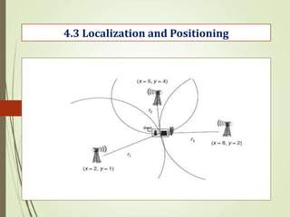
  • 123. 4.3 Localization and Positioning Possible Approaches: 1. Proximity 2. Trilateration and Triangulation 3. Scene Analysis Determining the position of sensor nodes with the assistance from some anchor points; not all nodes are necessarily in contact with all anchors
  • 124. . 4.3 Localization and Positioning Positioning in Multi hop Environment: 1. Connectivity in multihop network 2. Multihop range estimation 3. Iterative and collabrative mutilateraion 4. Probabilistic Positioning description and propagation
  • 125. 4.3 Localization and Positioning
  • 126. 4.3 Localization and Positioning
  • 127. . 4.4 Operating Systems for Wireless Sensor Networks WSNs can be used to monitor and/or control physical environment in a space where it is difficult or impossible to do so manually. A WSN is generally composed of a centralized station (sink) and tens, hundreds, or perhaps thousands of tiny sensor nodes such as Mote and Mica2 . WSNs are a special type of distributed network system that is similar to database, real-time, and embedded systems. The basic function of WSNs is to collect information and to support certain applications specific to the task of WSN deployment. Commercially available sensor nodes are categorized into four groups:
  • 128. 4.4 Operating Systems for Wireless Sensor Networks 1. Specialized sensing platforms such as the Spec node designed at the University of California–Berkeley. 2. Generic sensing platforms such as Berkeley motes 3. High-bandwidth sensing platforms such as iMote 4. Gateway platforms such as Stargate The differences in the sensor types above are in the function of the sensor, frequency of the microprocessor, memory size, and transceiver bandwidth. Although these nodes have different characteristics, their basic hardware components are the same: a physical sensor, a microprocessor or microcontroller, a memory, a radio transceiver, and a battery. Each sensor node needs an operating system (OS) that can control the hardware, Provide hardware abstraction to application software, and fill in the gap between applications and the underlying hardware
  • 129. . 4.4 Operating Systems for Wireless Sensor Networks Operating system design issues: Traditional operating systems are system software, including programs that manage computing resources, control peripheral devices, and provide software abstraction to the application software. Traditional OS functions are therefore to manage processes, memory, CPU time, file system, and devices.. This is often implemented in a modular and layered fashion, including a lower layer of kernels and a higher layer of system libraries. Traditional OSs are not suitable for wireless sensor networks because WSNs have constrained resources and diverse data-centric applications, in addition to a variable topology. WSNs need a new type of operating system, considering their special characteristics.
  • 130. 4.4 Operating Systems for Wireless Sensor Networks Operating system design issues: 1. Process management and scheduling 2.Memory management 3. kernel model 4. Application program interface (API). 5. Code upgrade and reprogramming Sensor operating systems (SOS) should embody the following functions: 1. Should be compact and small in size since the sensor nodes have very small memory. 2. Should provide real-time support, since there are real-time applications, especially when actuators are involved 3. Should provide efficient resource management mechanisms in order to allocate microprocessor time and limited memory. 4. Should support reliable and efficient code distribution since the functionality performed by the sensor nodes may need to be changed after deployment. 5. Should support power management, which helps to extend the system lifetime and improve its performance. 6. Should provide a generic programming interface up to sensor middleware or application software.
  • 131. . 4.4 Operating Systems for Wireless Sensor Networks Examples of Operating Systems: 1. TinyOS 2 .Mate, 3 .MagnetOS, 4 .MANTIS, 5 .OSPM 6 .EYES OS 7 .SenOS, 8 .EMERALDS 9 . PicOS The major issues for the design of operation systems for WSNs are size (memory requirement), energy-efficient IPCs and task scheduling, effective code distribution and upgrades, and finally, generic application programming interfaces.
  • 132. . TinyOS: 4.4 Operating Systems for Wireless Sensor Networks The design of tinyos allows application software to access hardware directly when required. Tinyos is a tiny microthreaded OS that attempts to address two issues: how to guarantee concurrent data flows among hardware devices, and how to provide modularized components with little processing and storage overhead. TinyOS uses an event-based model to support high levels of concurrent application in a very small amount of memory. It includes a tiny scheduler and a set of components. The scheduler schedules operation of those components. Each component consists of four parts: command handlers, event handlers, an encapsulated fixed-size frame, and a group of tasks.
  • 133. CONTENTS: 4.5 Sensor Node architecture 4.6 Programming Challenges OUTCOMES: To explaining about architecture of sensor node and challenges MODULE-3
  • 134. . 4.5 Sensor Node Hardware Sensor node hardware can be grouped into three categories, each of which entails a different set of trade-offs in the design choices: 1.Augmented general-purpose computers Ex: low power PCs, embedded PCs (e.g., PC104), custom-designed PCs and various personal digital assistants (PDA). 2. Dedicated embedded sensor nodes Ex: Berkeley mote family , the UCLA Medusa family , Ember nodes, and MIT μAMP 3. System-on-chip (SoC) nodes Ex: smart dust , the BWRC pico radio node , and the PASTA node Among these hardware platforms, the Berkeley motes, due to their small form factor, open source software development, and commercial availability, have gained wide popularity in the sensor network research community.
  • 135. 4.5 Sensor Node Hardware-Berkeley Motes The Berkeley motes are a family of embedded sensor nodes sharing roughly the same architecture. A comparison of Berkeley motes
  • 136. MICA MOTE: MICA motes have a two-CPU design 4.5 Sensor Node Hardware-Berkeley Motes MCU: an Atmel ATmega103L -512 KB flash memory -4 KB of data memory TR1000 chip set: -operating at 916 MHz - Max 50 kbps raw data rate -40 kbps transmission rate supports a 51 pin I/O A sensor/ actuator board can host : -a temperature sensor, - a light sensor, - an accelerometer, - a magnetometer, - a microphone, and - a beeper serial I/O (UART)
  • 137. The energy consumption of various components on a MICA mote. 4.5 Sensor Node Hardware-Berkeley Motes MATRUSRI ENGINEERING COLLEGE A Radio transmission bears the maximum power consumption. Another observation is that there are huge differences among the power consumption levels in the active mode, the idle mode, and the suspend mode of the MCU
  • 138. Traditional programming technologies rely on operating systems to provide abstraction for processing, I/O, networking, and user interaction hardware 4.6. Programming Challenges MATRUSRI ENGINEERING COLLEGE Traditional embedded system programming interface
  • 139. 4.6 Programming Challenges MATRUSRI ENGINEERING COLLEGE When applying traditional model to programming networked embedded systems, such as sensor networks, the application programmers need to explicitly deal with:  message passing, event synchronization,  interrupt handing, and sensor reading An application is typically implemented as a finite state machine (FSM) that covers all extreme cases: unreliable communication channels,  long delays, irregular arrival of messages, simultaneous events
  • 140. 4.6 Programming Challenges MATRUSRI ENGINEERING COLLEGE For resource-constrained Embedded systems with real-time requirements, several mechanisms are used in embedded operating systems to  reduce code size,  improve response time, and  reduce energy consumption Embedded operating systems tend to expose more hardware controls to the programmers, who now have to directly face device drivers and scheduling algorithms, and optimize code at the assembly level. Although these techniques may work well for small, stand-alone embedded systems, they do not scale up for the Programming of sensor networks for two reasons: 1. Sensor networks are large-scale distributed systems, where global properties are derivable from program execution in a massive number of distributed nodes. 2. As sensor nodes deeply embed into the physical world, a sensor network should be able to respond to multiple concurrent stimuli at the speed of changes of the physical phenomena of interest.
  • 141. CONTENTS: 4.7. Node-level software platforms 4.8. Node- level simulator 4.9 Sate centric Programming OUTCOMES: To understand the concepts of node-level software and simulations MODULE-4 MATRUSRI ENGINEERING COLLEGE
  • 142. 4.7. Node-level software platforms MATRUSRI ENGINEERING COLLEGE Most design methodologies for sensor network software are node centric, where programmers think in terms of how a node should behave in the environment.  A node-level platform can be a node centric operating system, which provides hardware and networking abstractions of a sensor node to programmers, or it can be a language platform, which provides a library of components to programmers. Typical operating system abstracts the hardware platform by providing a set of services for applications, including -file management, -memory allocation, -task scheduling, -peripheral device drivers, and -networking.
  • 143. 4.7. Node-level software platforms MATRUSRI ENGINEERING COLLEGE Operating System: TinyOS TinyOS aims at supporting sensor network applications on resource constrained hardware platforms, such as the Berkeley motes. To ensure that an application code has an extremely small footprint, TinyOS chooses to have no file system, supports only static memory allocation, implements a simple task model, and provides minimal device and networking abstractions
  • 144. . 4.7. Node-level software platforms MATRUSRI ENGINEERING COLLEGE The Field Monitor application for sensing and sending measurements
  • 145. 4.8 Node-Level Simulators MATRUSRI ENGINEERING COLLEGE Node-level design methodologies are usually associated with simulators that simulate the behavior of a sensor network on a per-node basis. Using simulation, designers can quickly study the performance (in terms of timing, power, bandwidth, and scalability) of potential algorithms without implementing them on actual hardware and dealing with the vagaries of actual physical phenomena. A node-level simulator typically has the following components: Sensor node model Communication model Physical environment model: Statistics and visualization A sensor network simulator simulates the behavior of a subset of the sensor nodes with respect to time. Depending on how the time is advanced in the simulation, there are two types of execution models: Cycle-driven simulation (CD) and Discrete-event simulation (DE)
  • 146. . 4.8 Node-Level Simulators MATRUSRI ENGINEERING COLLEGE A Cycle-driven (CD) simulation discretizes the continuous notion of real time into (typically regularly spaced) ticks and simulates the system behavior at these ticks. At each tick, the physical phenomena are first simulated, and then all nodes are checked to see if they have anything to sense, process, or communicate. A Discrete-event (DE) simulator assumes that the time is continuous and an event may occur at any time. An event is a 2-tuple with a value and a time stamp indicating when the event is supposed to be handled. There is no general CD simulator that fits all sensor network simulation tasks. We have come across a number of homegrown simulators written in Matlab, Java, and C++ Many of them are developed for particular applications and exploit application-specific assumptions to gain efficiency.
  • 147. . 4.8 Node-Level Simulators MATRUSRI ENGINEERING COLLEGE DE simulations are sometimes considered as good as actual implementations, because of their continuous notion of time and discrete notion of events. There are several open-source or commercial simulators available. One class of these simulators comprises extensions of classical network simulators, such as  ns-2,  J-Sim (previously known as JavaSim), and GloMoSim/QualNet.8 (The focus of these simulators is on network modeling, protocols stacks, and simulation performance). Another class of simulators, sometimes called softwarein-the-loop simulators, incorporate the actual node software into the simulation. For this reason, they are typically attached to particular hardware platforms and are less portable. Examples in TOSSIM for Berkeley motes and Em* (pronounced em star) for Linux-based nodes such as Sensoria WINS NG platforms
  • 148. Ns-2 simulator and its sensor network extensions: 4.8 Node-Level Simulators-NS 2 MATRUSRI ENGINEERING COLLEGE The simulator ns-2 is an open-source network simulator that was originally designed for wired, IP networks. Extensions have been made to simulate Wireless/mobile networks (e.g., 802.11 MAC and TDMA MAC) and more recently sensor networks. While the original ns-2 only supports logical addresses for each node, the wireless/mobile extension of it introduces the notion of node locations and a simple wireless channel model. This is not a trivial extension, since once the nodes move, the simulator needs to check for each physical layer event whether the destination node is within the communication range. For a large network, this significantly slows down the simulation speed.
  • 149. MATRUSRI ENGINEERING COLLEGE 4.8 Node-Level Simulators There are at least two efforts to extend ns-2 to simulate sensor networks: 1. SensorSim from UCLA9 and 2. NRL sensor network extension from the Navy Research Laboratory SensorSim aims at providing an energy model for sensor nodes and communication, so that power properties can be simulated . It also supports hybrid simulation. NRL sensor network extension provides a flexible way of modeling physical phenomena in a discrete event simulator. Physical phenomena are modeled as network nodes which communicate with real nodes through physical layers. The receiving nodes simply have a sensor stack parallel to the network stack that processes these events.
  • 150. 4.8 Node-Level Simulators MATRUSRI ENGINEERING COLLEGE The main functionality of ns-2 is implemented in C++, while the dynamics of the simulation (e.g., time-dependent application characteristics) is controlled by Tcl scripts. Basic components in ns-2 are the layers in the protocol stack. They implement the handlers interface, indicating that they handle events. Events are communication packets that are passed between consecutive layers within one node, or between the same layers across nodes. Advantage of ns-2 is its rich libraries of protocols for nearly all network layers and for many routing mechanisms. TCP: reno, tahoe, vegas, and SACK implementations • MAC: 802.3, 802.11, and TDMA • Ad hoc routing: DSDV,DSR, AODV routing, and TORA • Sensor network routing: Directed diffusion, geographical routing (GEAR) and geographical adaptive fidelity (GAF) routing.
  • 151. . 4.8 Node-Level Simulators-TOSSIM MATRUSRI ENGINEERING COLLEGE TOSSIM is a dedicated simulator for TinyOS applications running on one or more Berkeley motes. The key design decisions on building TOSSIM were to make it scalable to a network of potentially thousands of nodes, and to be able to use the actual software code in the Simulation. To achieve these goals, TOSSIM takes a cross-compilation approach that compiles the nesC source code into components in the simulation The event-driven execution model of TinyOS greatly simplifies the design of TOSSIM. By replacing a few low-level components, such as the A/D conversion (ADC), the system clock, and the radio front end, TOSSIM translates hardware interrupts into discrete event simulator events. The simulator event queue delivers the interrupts that drive the execution of a node. The upper-layer TinyOS code runs unchanged.
  • 152. 4.8 Node-Level Simulators-TOSSIM MATRUSRI ENGINEERING COLLEGE TOSSIM uses a simple but powerful abstraction to model a wireless network. A network is a directed graph, where each vertex is a sensor node and each directed edge has a bit-error rate. Each node has a private piece of state representing what it hears on the radio channel. By setting connections among the vertices in the graph and a biterror rate on each connection, wireless channel characteristics, such as imperfect channels, hidden terminal problems, and asymmetric links, can be easily modeled. Wireless transmissions are simulated at the bit level. If a bit error occurs, the simulator flips the bit. TOSSIM has a visualization package called TinyViz, which is a Java application that can connect to TOSSIM simulations.
  • 153. . 4.9 State-centric programming MATRUSRI ENGINEERING COLLEGE Many sensor network applications, such as target tracking, are not simply generic distributed programs over an ad hoc network of energy-constrained nodes. Deeply rooted in these applications is the notion of states of physical phenomena and models of their evolution over space and time. Some of these states may be represented on a small number of nodes and evolve over time, as in the target tracking problem while others may be represented over a large and spatially distributed number of nodes, as in tracking a temperature contour. A distinctive property of physical states, such as location, shape, and motion of objects, is their continuity in space and time. Their sensing and control is typically done through sequential state updates.
  • 154. . 4.9 State-centric programming MATRUSRI ENGINEERING COLLEGE System theories, the basis for most signal and information processing algorithms, provide abstractions for state update, such as: where x is the state of a system, u are the inputs, y are the outputs, k is an integer update index over space and/or time, f is the state update function, and g is the output or observation function. This formulation is broad enough to capture a wide variety of algorithms in sensor fusion, signal processing, and control (e.g., Kalman filtering, Bayesian estimation, system identification, feedback control laws, and finite-state automata). However, in distributed real-time embedded systems such as sensor networks, the formulation is not so clean as represented in those equations. The relationships among subsystems can be highly complex and dynamic over space and time.
  • 155. 4.10 State-centric programming MATRUSRI ENGINEERING COLLEGE The following concerns must be properly addressed during the design to ensure the correctness and efficiency of the resulting systems: Where are the state variables stored?  Where do the inputs come from?  Where do the outputs go?  Where are the functions f and g evaluated?  How long does the acquisition of inputs take?  Are the inputs in uk collected synchronously?  Do the inputs arrive in the correct order through communication?  What is the time duration between indices k and k + 1? Is it a constant? These issues, addressing where and when, rather than how, to perform sensing, computation, and communication, play a central role in the overall system performance. However, these “nonfunctional” aspects of computation, related to concurrency, responsiveness, networking, and resource management, are not well supported by traditional programming models and languages. State-centric programming aims at providing design methodologies and frameworks that give meaningful abstractions for these issues, so that system designers can continue to write algorithms like top of an intuitive understanding of where and when the operations are performed.
  • 156. . 4.9 State-centric programming MATRUSRI ENGINEERING COLLEGE Collaboration Groups: A collaboration group is a set of entities that contribute to a state update. These entities can be physical sensor nodes, or they can be more abstract system components such as virtual sensors or mobile agents hopping among sensors. In this context, they are all referred to as agents. Example of Groups: Geographically Constrained Group. N-hop Neighborhood Group. Publish/Subscribe Group. Acquaintance Group. Using Multiple Types of Groups PIECES: A State-Centric Design Framework Principal Groups Mobility PIECES Simulator
  • 157. 1. What are the design issues for an operating system for WSN. 2. Explain about Berkeley motes . 3. Briefly explain bout Localization and Positioning 4. Discuss about Sensor tasking and control 5. Explain about Sensor tasking and control Assignment Question MATRUSRI ENGINEERING COLLEGE
  • 158. Questions & Answers MATRUSRI ENGINEERING COLLEGE S.NO QUESTION Blooms Taxonomy Level Course Outcome 1. What are the design factors for routing protocol of WSN. L1 CO4 2. Explain Clustering. L2 CO4 3. What is the Topology L1 CO4 4. What are the performance metrics for WSN. L1 CO4 5. Explain enabling technologies for WSN. L1 CO4 Short answer questions
  • 159. Questions & Answers MATRUSRI ENGINEERING COLLEGE S.NO QUESTION Blooms Taxonomy Level Course Outcome 1. What do you mean by state centric programming and explain its significance over generic distributed systems. L1 CO4 2. Explain how multi-target tracking problem is solved using state centric programming. L2 CO4 3. Write about MICA motes. L3 CO4 4. What are optimization goals and figures of merit in WSN. L1 CO4 5. Explain node level software platforms. L2 CO4 Long answer questions
  • 160. INTRODUCTION: UNIT-V: Security Issues In Wireless Sensor Networks OUTCOMES: Evaluate concepts of security in sensor networks MATRUSRI ENGINEERING COLLEGE WSNs suffer from many constraints, including low computation capability, small memory, limited energy resources, susceptibility to physical capture, and the use of insecure wireless communication channels. These constraints make security in WSNs a challenge.
  • 161. CONTENTS: Introduction OUTCOMES: To understand concepts of security in sensor networks. MODULE-I MATRUSRI ENGINEERING COLLEGE
  • 162. Contents: 5.1. Security architectures 5.2. Survey of Security protocols for Wireless Sensor Networks and their Comparisons OUTCOMES Evaluate concepts of security in sensor networks UNIT-V: Security Issues In Wireless Sensor Networks MATRUSRI ENGINEERING COLLEGE .
  • 163. . INTRODUCTION MATRUSRI ENGINEERING COLLEGE Advances in wireless communication and electronics have enabled the development of low-cost, low power, multifunctional sensor nodes. These tiny sensor nodes, consisting of sensing, data processing, and communication components, make it possible to deploy Wireless Sensor Networks (WSNs), which represent a significant improvement over traditional wired sensor networks. WSNs can greatly simplify system design and operation, as the environment being monitored does not require the communication or energy infrastructure associated with wired networks. WSNs are expected to be solutions to many applications, such as detecting and tracking the passage of troops and tanks on a battlefield, monitoring environmental pollutants, measuring traffic flows on roads, and tracking the location of personnel in a building. Many sensor networks have mission-critical tasks and thus require that security be considered.
  • 164. INTRODUCTION MATRUSRI ENGINEERING COLLEGE The differences between sensor networks and ad hoc networks are greatly affect how secure data-transfer. The limited energy and processing power of nodes makes the use of public key cryptography nearly impossible. Public key cryptography might be feasible in sensor networks it remains for the most part infeasible in WSNs most security schemes make use of symmetric key cryptography. One thing required in either case is the use of keys for secure communication. Managing key distribution is not unique to WSNs, but again constraints such as small memory capacity make centralized keying techniques impossible. Straight pair wise key sharing between every two nodes in a network does not scale to large networks with tens of thousands of nodes, as the storage requirements are too high. A security scheme in WSNs must provide efficient key distribution while maintaining the ability for communication between all relevant nodes.
  • 165. INTRODUCTION MATRUSRI ENGINEERING COLLEGE In addition to key distribution, secure routing protocols must be considered. These protocols are concerned with how a node sends messages to other nodes or a base station. A key challenge is that of authenticated broadcast. Existing authenticated broadcast methods often rely on public key cryptography and include high computational overhead making them infeasible in WSNs. Secure routing protocols proposed for use in WSNs, such as SPINS , must consider these factors. Additionally, the constraint on energy in WSNs leads to the desire for data aggregation. This aggregation of sensor data needs to be secure in order to ensure information integrity and confidentiality. While this is achievable through cryptography, an aggregation scheme must take into account the constraints in WSNs and the unique characteristics of the cryptography and routing schemes.
  • 166. . 5.1 Security Architecture MATRUSRI ENGINEERING COLLEGE .A WSN is usually composed of hundreds or thousands of sensor nodes. These sensor nodes are often densely deployed in a sensor field and have the capability to collect data and route data back to a base station (BS). A sensor consists of four basic parts: a sensing unit, a processing unit, a transceiver unit, and a power unit . It may also have additional application- dependent components such as a location finding system, power generator, and mobilizer
  • 167. 5.1 Security Architecture MATRUSRI ENGINEERING COLLEGE The protocol stack used in sensor nodes contains physical, data link, network, transport, and application layers defined as follows [4]: • Physical layer: responsible for frequency selection, carrier frequency generation, signal deflection, modulation, and data encryption • Data link layer: responsible for the multiplexing of data streams, data frame detection, medium access, and error control; as well as ensuring reliable point-to- point and point-to-multipoint connections • Network layer: responsible for specifying the assignment of addresses and how packets are forwarded • Transport layer: responsible for specifying how the reliable transport of packets will take place • Application layer: responsible for specifying how the data are requested and provided for both individual sensor nodes and interactions with the end user
  • 168. . 5.1 Security Architecture-Constraints in WSNs MATRUSRI ENGINEERING COLLEGE Constraints in WSNs Variety of real-life sensor nodes Individual sensor nodes in a WSN are inherently resource constrained. They have limited processing capability, storage capacity, and communication bandwidth. Each of these limitations is due in part to the two greatest constraints — limited energy and physical size.
  • 169. . 5.1 Security Architecture-Constraints in WSNs MATRUSRI ENGINEERING COLLEGE The design of security services in WSNs must consider the hardware constraints of the sensor nodes: • Energy: Energy consumption in sensor nodes can be categorized into three parts: –Energy for the sensor transducer –Energy for communication among sensor nodes –Energy for microprocessor computation Computation: The embedded processors in sensor nodes are generally not as powerful as those in nodes of a wired or ad hoc network. Memory: Transmission range:
  • 170. 5.2 Survey of Security protocols for WSN-Security requirements MATRUSRI ENGINEERING COLLEGE The goal of security services in WSNs is to protect the information and resources from attacks and misbehavior. The security requirements in WSNs include: Availability, Authorization Authentication Confidentiality Integrity, Non-repudiation Freshness As new sensors are deployed and old sensors fail, we suggest that forward and backward secrecy should also be considered: Forward secrecy Backward Secrecy
  • 171. 5.2 Survey of Security protocols for WSN: Threat model MATRUSRI ENGINEERING COLLEGE In WSNs, it is usually assumed that an attacker may know the security mechanisms that are deployed in a sensor network; they may be able to compromise a node or even physically capture a node. once a node is compromised, the attacker is capable of stealing the key materials contained within that node. Base stations in WSNs are usually regarded as trustworthy. Attacks in sensor networks can be classified into the following categories: • Outsider versus insider attacks: • Passive versus active attacks: • Mote-class versus laptop-class attacks:
  • 172. 5.2 Survey of Security protocols for WSN:Evaluation MATRUSRI ENGINEERING COLLEGE The following metrics to evaluate whether a security scheme is appropriate in WSNs: Security: Resiliency: Energy efficiency: Flexibility: Scalability: Fault-tolerance: Self-healing: Assurance:
  • 173. 5.2 Survey of Security protocols for WSN: Attacks in sensor networks MATRUSRI ENGINEERING COLLEGE WSNs are vulnerable to various types of attacks. According to the security requirements in WSNs, these attacks can be categorized as: Attacks on secrecy and authentication: Attacks on network availability: Stealthy attacks against service integrity: In these attacks, keeping the sensor network available for its intended use is essential. DoS (Denial-of-service) attacks against WSNs may permit real-world damage to the health and safety of people. The DoS attack usually refers to an adversary’s attempt to disrupt, subvert, or destroy a network However, a DoS attack can be any event that diminishes or eliminates a network’s capacity to perform its expected function. Sensor networks are usually divided into layers, and this layered architecture makes WSNs vulnerable to DoS attacks, as DoS attacks may occur in any layer of a sensor network.
  • 174. . 5.2 Survey of Security protocols for WSN: Attacks in sensor networks MATRUSRI ENGINEERING COLLEGE PHYSICAL LAYER Jamming Tampering LINK LAYER Collisions Exhaustion Unfairness NETWORK AND ROUTING LAYER: The network and routing layer of sensor networks is usually designed according to the following principles. • Power efficiency is an important consideration. • Sensor networks are mostly data-centric. • An ideal sensor network has attribute-based addressing and location awareness.
  • 175. 5.2 survey of security protocols for WSN :Attacks in sensor networks MATRUSRI ENGINEERING COLLEGE Sensor network layers and denial-of-service defenses
  • 176. 5.2 Survey of Security protocols for WSN: Attacks in sensor networks MATRUSRI ENGINEERING COLLEGE The attacks in the network and the routing layer include the following: Spoofed, Altered, or Replayed Routing Information Selective Forwarding Sinkhole Sybil Wormholes Hello Flood Attacks Acknowledgment Spoofing TRANSPORT LAYER: Flooding De-synchronization
  • 177. CONTENTS: 5.2 survey of security protocols for WSN: CRYPTOGRAPHY in WSNs OUTCOMES: Discuss about survey of security protocols of WSNs . MODULE-3 MATRUSRI ENGINEERING COLLEGE
  • 178. 5.2 Survey of Security protocols for WSN: Cryptography in WSNs MATRUSRI ENGINEERING COLLEGE Selecting the most appropriate cryptographic method is vital in WSNs because all security services are ensured by cryptography. Cryptographic methods used in WSNs should meet the constraints of sensor nodes and be evaluated by code Size, Data size, Processing time, and Power consumption Public key cryptography, Symmetric key cryptography. Public key cryptography: average ECC and RSA execution times Public key cryptography: average energy costs of digital signature and key exchange omputations
  • 179. . 5.2 Survey of Security protocols for WS: Cryptography MATRUSRI ENGINEERING COLLEGE Symmetric key cryptography: average RC5 and skipjack execution times Symmetric key cryptography: average energy numbers for AES and SHA-1 Tables shows the execution time and energy cost of two symmetric cryptography protocols on an Atmel ATmega128 processor The performance of symmetric key cryptography is mainly decided by the following factors: • Embedded data bus width • Instruction set
  • 180. 5.2 Survey of Security protocols for WSN : Key management protocols MATRUSRI ENGINEERING COLLEGE Key management is a core mechanism to ensure the security of network services and applications in WSNs. The goal of key management is to establish required keys between sensor nodes which must exchange data. According to the network structure, the protocol scan be divided into centralized key schemes and distributed key schemes. Taxonomy of key management protocols in WSNs
  • 181. 5.3 Classification and comparison of key management protocols in WSNs MATRUSRI ENGINEERING COLLEGE
  • 182. 5.2 Survey of Security protocols for WSN :Secure routing protocols MATRUSRI ENGINEERING COLLEGE Many routing protocols have been specifically designed for WSNs. These routing protocols can be divided into three categories according to the network structure: flat-based routing, hierarchical-based routing, and location-based routing In flat-based routing, all nodes are typically assigned equal roles or functionality. In hierarchical-based routing, nodes play different roles in the network. In location-based routing, sensor node positions are used to route data in the network. Most network layer attacks against sensor networks fall into one of the categories described above, namely: • Spoofed, altered, or replayed routing information • Wormholes • Selective forwarding • Sybil • Sinkhole • Acknowledgment spoofing • Hello flood attacks
  • 183. . 5.2 Survey of Security protocols for WSN :Secure routing protocols MATRUSRI ENGINEERING COLLEGE A secure routing protocol depends on an appropriate key management scheme in a WSN, which has been discussed earlier. Before a routing protocol starts, sensor nodes should have been loaded with proper keys (e.g., the key for confidentiality, authentication, etc.). One of the fundamental security services in sensor networks is broadcast authentication, which enables the base station to broadcast authenticated data to the entire sensor network. Using a time-released key chain for source authentication Broadcast authentication Authenticated broadcast are impractical in WSNs for the following reasons: • Most proposals rely on public key cryptography for the authentication. However, public key cryptography is impractical for WSNs; • Even one-time signature schemes that are based on symmetric key cryptography have too much overhead.
  • 184. : 5.2 Survey of Security protocols for WSN :Secure routing protocols MATRUSRI ENGINEERING COLLEGE Secure routing The goal of a secure routing protocol is to ensure the integrity, authentication, and availability of messages. SNEP offers the following properties: semantic security, data authentication,  replay protection, weak freshness, and low communication overhead.
  • 185. 5.2 Survey of Security protocols for WSN :Secure routing protocols MATRUSRI ENGINEERING COLLEGE Comparison of secure routing protocols SPINS identifies two types of freshness: weak freshness and strong freshness. Weak freshness provides partial message ordering and carries no delay information while strong freshness provides a total order on a request–response pair and allows for delay estimation.
  • 186. 5.2 Survey of Security protocols for WSN : Secure data aggregation MATRUSRI ENGINEERING COLLEGE Secure data aggregation in WSNs: Data aggregation (fusion) protocols aim at eliminating redundant data transmitted across the network and are essential for energy-constrained WSNs. Traditional data aggregation techniques include simple types of queries such as SUM, COUNT, AVERAGE, and MIN/MAX. According to the protocol operation, secure data aggregation can be classified into two categories: Plaintext based and Cipher based
  • 187. . Assignment Question MATRUSRI ENGINEERING COLLEGE 1. Explain the Hardware components of Security Architecture 2. Classification and comparison of key management protocols in WSNs. 3. What are the Security Routing Protocols. 4. Discuss about Cryptography in WSNs. 5. What are the Design constraints of security services in WSNs
  • 188. Questions & Answers MATRUSRI ENGINEERING COLLEGE S.NO QUESTION Blooms Taxonomy Level Course Outcome 1. What are the security requirements? L1 CO5 2. Draw the block diagram of key management Protocols in WSNs L1 CO5 3. Discuss about Secure Data Aggregation. L3 CO5 4. List out the Attacks in Wireless sensor networks. L1 CO5 5. What are the metrics to evaluate the security of WSNs L1 CO5 Short answer questions
  • 189. Questions & Answers MATRUSRI ENGINEERING COLLEGE S.NO QUESTION Blooms Taxonomy Level Course Outcome 1. Differences between WSNs security protocols L3 CO5 2. Draw and Explain about WSN Security architectures L2 CO5 3. Explain the attacks in Sensor Networks L2 CO5 4. Discuss about Cryptography in WSNs L4 CO5 5. Explain about Key Management Protocols L2 CO5 Long answer questions