SIMULATION ANALYSIS OF CLOSED LOOP DUAL INDUCTOR CURRENT-FED PUSH-PULL CONVERTER BY USING SOFT SWITCHING
1 like296 views

The document discusses the simulation analysis of a closed-loop dual inductor current-fed push-pull converter (cfpp), emphasizing its application in boosting DC voltage for various electronic devices. It highlights the converter's ability to achieve zero-voltage and zero-current switching (ZVS and ZCS) to reduce switching losses while maintaining design efficiency. The findings include successful simulation results conducted via MATLAB/Simulink, demonstrating controlled output voltage regulation amid load variations.
![Journal for Research | Volume 02 | Issue 04 | June 2016
ISSN: 2395-7549
All rights reserved by www.journalforresearch.org 75
Simulation Analysis of Closed Loop Dual Inductor
Current-Fed Push-Pull Converter by using Soft
Switching
Ms. Manasa M P Mrs. Sujo Oommen
PG Scholar Assistant Professor
Department of Electrical and Electronics Engineering Department of Electrical and Electronics Engineering
RITM, Bengaluru-64 RITM, Bengaluru-64
Abstract
The current electronic devices require DC power source, which is taken from a battery or DC power supply. DC-DC converter is
utilized to get regulated dc voltage from unregulated one. Switched mode power supply (SMPS) are commonly used in industrial
applications, because of more advantages compared to linear power supply. In SMPS we have isolated and non-isolated
converters, where isolated converters are frequently used, in order to get more voltage with multiple outputs. So among different
isolated converters, push-pull converter is chosen for micro converter applications to obtain high voltage conversion ratio by
using HF transformer, due to their better utilization of transformer. New methodology of control is implemented for making ZVS
and ZCS at same time and to reduce the number of switches in the secondary side of dual inductor CFPP converter, which is a
voltage doubler circuit. This becomes the solution for problem identification. Thus this converter with soft-switching reduces the
switching losses.The current-fed push-pull converters are used in many applications like photo-voltaic (PV) power converters for
boosting the output voltage. Push-pull converter is chosen for micro converter applications, to obtain high voltage conversion
ratio by using high frequency (HF) transformer, due to their better utilization of transformer. This deals with the design of dual
inductor CFPP converter, where zero voltage switching (ZVS) and zero current switching (ZCS) is achieved for the primary side
of the converter by using secondary switches. Primary side switches are controlled by closed loop control topology. The
secondary side is made with voltage doubler to obtain high voltage. Open loop and closed loop control of dual inductor current
fed push pull converter simulation is finished by MATLAB/SIMULINK and their outcomes are analyzed.
Keywords: Dual inductor current-fed push-pull converter, voltage doubler, zero-voltage switching, zero-current-
switching, high frequency, matrix laboratory
_______________________________________________________________________________________________________
I. INTRODUCTION
The use of renewable energy such as solar energy is increasing now-a-days, due to its ecofriendly to nature. Photovoltaic effect is
the standard used to change over sunlight based vitality into direct current power by utilizing semiconductor materials [1].
Photovoltaic framework contains sun powered boards, in which it comprises of sun oriented cells to supply sun based energy to
many of the applications like solar batteries, solar water heater, solar lamp etc. Select the semiconductor materials which are
having lower energy payback period and reduced CO2 emission. The fuel cell is more advantageous compared to solar and wind,
as its output is continuous with stable operation having high efficiency without CO2 emission. Fuel cell finds application in fuel
cell vehicles, which is proved as zero- emission vehicles [2]. To consolidate PV boards to a typical DC-transport in the
concentrated inverter based appropriated PV transformation frameworks, use smaller scale converter which is an isolated DC-DC
converter. The PV generated Voltage (36V to 72V) is less, so we have to use converters which are having high voltage
conversion ratios to convert it to high DC-bus voltages (200V to 400V). Isolated converters are better to choose, as it allows
voltage conversion ratio more than 10 using high-frequency isolation transformer [3]. The different types of isolated DC-DC
converters are current-fed and a voltage-fed DC-DC converter depends on switching control technique and position of the
inductors. Current fed topologies are more valuable contrasted with voltage fed converters because of dynamic boosting and
inactive voltage addition of HF transformer in low voltage and high current application, for example, PV and fuel cell. We have
distinctive separated topologies, for example, fly-back; forward converters, half-bridge and full-bridge among this push-pull
appear to be better, as it has better transformer usage with less number of switches contrasted with full-bridge. Push-pull
converters come in two structures (dual and single inductor), every topology has its own particular plus points and drawbacks as
showed up in [4] and both are reasonable for PV small scale converter applications.
DC-DC converters such as push pull; by switching 2 switches alternatively pulses of opposite polarity are produced across
both windings of the transformer. As we perceived how current-fed push-pull (CFPP) converters is more valuable contrasted
with voltage-fed, yet it has a few inconveniences moreover. Push-pull has most common problem is that voltage surges occur at
turn-OFF of the primary side power switches. The voltage surges are due to sudden change in voltage and leakage inductance of
isolation transformer. To overcome this disadvantage, snubbers circuits are provided, which makes to release stored energy from](https://image.slidesharecdn.com/j4rv2i4035-170302125401/85/SIMULATION-ANALYSIS-OF-CLOSED-LOOP-DUAL-INDUCTOR-CURRENT-FED-PUSH-PULL-CONVERTER-BY-USING-SOFT-SWITCHING-1-320.jpg)
![Simulation Analysis of Closed Loop Dual Inductor Current-Fed Push-Pull Converter by using Soft Switching
(J4R/ Volume 02 / Issue 04 / 015)
All rights reserved by www.journalforresearch.org 76
alternate path of leakage inductor across the switches. All HF power converters, specifically during turn-ON of push-pull
converters, switching loss are the common problem. Zero-voltage-switching (ZVS) and zero-current-switching (ZCS) are the soft
switching techniques which are applied to minimize switching losses in the converters. The switching control strategy is
proposed in [5] to have both ZVS at turn-ON, ZCS at turn-OFF of primary side switches of HF transformer in single inductor
CFPP converters. On secondary side we have voltage doubler circuit in order to boost the voltage by avoiding size of high
frequency transformer. The operation of switching control strategy and its closed loop [6] is introduced in segment II. The
simulation results are clarified in segment III to understand the operation of proposed dual inductor CFPP converter.
II. CLOSED LOOP DUAL INDUCTOR CFPP CONVERTER
Closed loop method of dual inductor CFPP converter provides gating signals, which are provided only to primary switches by
manually tuning the PI controller and Fig.1 shows its block diagram. If there are any variations in the load side with input
voltage 12V fixed, closed loop is regulating the output voltage of 350V. Here both output voltage and primary side current is
controlling by two PI blocks, which are meant for duty ratio and current control.
Fig. 1: Block diagram of closed loop of dual inductor CFPP converter
Dual inductor CFPP converter:A.
A switching control methodology is proposed for the double inductor CFPP converters with secondary side voltage doubler
circuit to turn-on and turn-off the primary side power switches with ZVS and ZCS as appeared in Fig.2. And also leakage
inductance of HF isolation transformer La is as shown in Fig.2 and its corresponding waveforms in Fig.3 for each equivalent
interval.
Fig. 2: Open Loop Circuit Diagram for Dual Inductor CFPP Converter
Assumptions used for analyzing dual inductor CFPP converter are as follows:-
1) All power switches are ideal.
2) Input filter is large enough to assume continuous current.
3) Magnetizing inductance of transformer is infinite.
Dual inductor CFPP converter expected waveforms](https://image.slidesharecdn.com/j4rv2i4035-170302125401/85/SIMULATION-ANALYSIS-OF-CLOSED-LOOP-DUAL-INDUCTOR-CURRENT-FED-PUSH-PULL-CONVERTER-BY-USING-SOFT-SWITCHING-2-320.jpg)


![Simulation Analysis of Closed Loop Dual Inductor Current-Fed Push-Pull Converter by using Soft Switching
(J4R/ Volume 02 / Issue 04 / 015)
All rights reserved by www.journalforresearch.org 83
controlled by closed loop control topology. Closed loop results are provided such that, if there are any variations in the load, the
CFPP converter is regulating the output voltage of 350V. Simulation of both open and closed loop CFPP converter is done by
using SIMULINK. Controlling of 4 switches along with regulating for more voltage becomes difficult by closed loop strategy,
which becomes the future work of the project.
REFERENCES
[1] W. Li, Y. Zhao, J. Wu, and X. He, “Interleaved high step-up converter with winding-cross-coupled inductors and voltage multiplier cells,” IEEE Trans.
Power Electron., vol. 27, no. 1, pp. 133–143, 2012.
[2] U. R. Prasanna, A. K. Rathore, and S. K. Mazumder, “Novel zero-current switching current-fed half-bridge isolated DC/DC converter for fuel cell based
applications,’’ IEEE Trans. Ind. Appl., vol. 49, no. 4, pp. 1658–1668, 2013.
[3] Radha Sree Krishns Moorthy and Akshay Rathore, “ Zero current switching current-fed parallel resonant push-pull(CFPRPP)converter”, International
Power Electronics Conference, 978-1-4799-2705, 2014.
[4] W. de A. Filho and I. Barbi, “A comparison between two current-fed push-pull DC-DC converters-analysis, design and experimentation,’’ in Proc. IEEE
INTELEC, 1996, vol. 00, pp. 313–320.
[5] K. Abarna, S. Divya and P. Rajeswari, “Soft-switching current-fed push-pull converter for PV application”, ARPN, vol. 10, No.8, ISSN 1819-6608, May
2015.
[6] P. Sivaskthy and Dr. R. Anushya, “Closed loop residential photovoltaic power system with soft-switching push-pull front-end converter,” vol 3 Issue 6,
ISSN 2321-919X, June 2015.](https://image.slidesharecdn.com/j4rv2i4035-170302125401/85/SIMULATION-ANALYSIS-OF-CLOSED-LOOP-DUAL-INDUCTOR-CURRENT-FED-PUSH-PULL-CONVERTER-BY-USING-SOFT-SWITCHING-9-320.jpg)
SIMULATION ANALYSIS OF CLOSED LOOP DUAL INDUCTOR CURRENT-FED PUSH-PULL CONVERTER BY USING SOFT SWITCHING
- 1. Journal for Research | Volume 02 | Issue 04 | June 2016 ISSN: 2395-7549 All rights reserved by www.journalforresearch.org 75 Simulation Analysis of Closed Loop Dual Inductor Current-Fed Push-Pull Converter by using Soft Switching Ms. Manasa M P Mrs. Sujo Oommen PG Scholar Assistant Professor Department of Electrical and Electronics Engineering Department of Electrical and Electronics Engineering RITM, Bengaluru-64 RITM, Bengaluru-64 Abstract The current electronic devices require DC power source, which is taken from a battery or DC power supply. DC-DC converter is utilized to get regulated dc voltage from unregulated one. Switched mode power supply (SMPS) are commonly used in industrial applications, because of more advantages compared to linear power supply. In SMPS we have isolated and non-isolated converters, where isolated converters are frequently used, in order to get more voltage with multiple outputs. So among different isolated converters, push-pull converter is chosen for micro converter applications to obtain high voltage conversion ratio by using HF transformer, due to their better utilization of transformer. New methodology of control is implemented for making ZVS and ZCS at same time and to reduce the number of switches in the secondary side of dual inductor CFPP converter, which is a voltage doubler circuit. This becomes the solution for problem identification. Thus this converter with soft-switching reduces the switching losses.The current-fed push-pull converters are used in many applications like photo-voltaic (PV) power converters for boosting the output voltage. Push-pull converter is chosen for micro converter applications, to obtain high voltage conversion ratio by using high frequency (HF) transformer, due to their better utilization of transformer. This deals with the design of dual inductor CFPP converter, where zero voltage switching (ZVS) and zero current switching (ZCS) is achieved for the primary side of the converter by using secondary switches. Primary side switches are controlled by closed loop control topology. The secondary side is made with voltage doubler to obtain high voltage. Open loop and closed loop control of dual inductor current fed push pull converter simulation is finished by MATLAB/SIMULINK and their outcomes are analyzed. Keywords: Dual inductor current-fed push-pull converter, voltage doubler, zero-voltage switching, zero-current- switching, high frequency, matrix laboratory _______________________________________________________________________________________________________ I. INTRODUCTION The use of renewable energy such as solar energy is increasing now-a-days, due to its ecofriendly to nature. Photovoltaic effect is the standard used to change over sunlight based vitality into direct current power by utilizing semiconductor materials [1]. Photovoltaic framework contains sun powered boards, in which it comprises of sun oriented cells to supply sun based energy to many of the applications like solar batteries, solar water heater, solar lamp etc. Select the semiconductor materials which are having lower energy payback period and reduced CO2 emission. The fuel cell is more advantageous compared to solar and wind, as its output is continuous with stable operation having high efficiency without CO2 emission. Fuel cell finds application in fuel cell vehicles, which is proved as zero- emission vehicles [2]. To consolidate PV boards to a typical DC-transport in the concentrated inverter based appropriated PV transformation frameworks, use smaller scale converter which is an isolated DC-DC converter. The PV generated Voltage (36V to 72V) is less, so we have to use converters which are having high voltage conversion ratios to convert it to high DC-bus voltages (200V to 400V). Isolated converters are better to choose, as it allows voltage conversion ratio more than 10 using high-frequency isolation transformer [3]. The different types of isolated DC-DC converters are current-fed and a voltage-fed DC-DC converter depends on switching control technique and position of the inductors. Current fed topologies are more valuable contrasted with voltage fed converters because of dynamic boosting and inactive voltage addition of HF transformer in low voltage and high current application, for example, PV and fuel cell. We have distinctive separated topologies, for example, fly-back; forward converters, half-bridge and full-bridge among this push-pull appear to be better, as it has better transformer usage with less number of switches contrasted with full-bridge. Push-pull converters come in two structures (dual and single inductor), every topology has its own particular plus points and drawbacks as showed up in [4] and both are reasonable for PV small scale converter applications. DC-DC converters such as push pull; by switching 2 switches alternatively pulses of opposite polarity are produced across both windings of the transformer. As we perceived how current-fed push-pull (CFPP) converters is more valuable contrasted with voltage-fed, yet it has a few inconveniences moreover. Push-pull has most common problem is that voltage surges occur at turn-OFF of the primary side power switches. The voltage surges are due to sudden change in voltage and leakage inductance of isolation transformer. To overcome this disadvantage, snubbers circuits are provided, which makes to release stored energy from
- 2. Simulation Analysis of Closed Loop Dual Inductor Current-Fed Push-Pull Converter by using Soft Switching (J4R/ Volume 02 / Issue 04 / 015) All rights reserved by www.journalforresearch.org 76 alternate path of leakage inductor across the switches. All HF power converters, specifically during turn-ON of push-pull converters, switching loss are the common problem. Zero-voltage-switching (ZVS) and zero-current-switching (ZCS) are the soft switching techniques which are applied to minimize switching losses in the converters. The switching control strategy is proposed in [5] to have both ZVS at turn-ON, ZCS at turn-OFF of primary side switches of HF transformer in single inductor CFPP converters. On secondary side we have voltage doubler circuit in order to boost the voltage by avoiding size of high frequency transformer. The operation of switching control strategy and its closed loop [6] is introduced in segment II. The simulation results are clarified in segment III to understand the operation of proposed dual inductor CFPP converter. II. CLOSED LOOP DUAL INDUCTOR CFPP CONVERTER Closed loop method of dual inductor CFPP converter provides gating signals, which are provided only to primary switches by manually tuning the PI controller and Fig.1 shows its block diagram. If there are any variations in the load side with input voltage 12V fixed, closed loop is regulating the output voltage of 350V. Here both output voltage and primary side current is controlling by two PI blocks, which are meant for duty ratio and current control. Fig. 1: Block diagram of closed loop of dual inductor CFPP converter Dual inductor CFPP converter:A. A switching control methodology is proposed for the double inductor CFPP converters with secondary side voltage doubler circuit to turn-on and turn-off the primary side power switches with ZVS and ZCS as appeared in Fig.2. And also leakage inductance of HF isolation transformer La is as shown in Fig.2 and its corresponding waveforms in Fig.3 for each equivalent interval. Fig. 2: Open Loop Circuit Diagram for Dual Inductor CFPP Converter Assumptions used for analyzing dual inductor CFPP converter are as follows:- 1) All power switches are ideal. 2) Input filter is large enough to assume continuous current. 3) Magnetizing inductance of transformer is infinite. Dual inductor CFPP converter expected waveforms
- 3. Simulation Analysis of Closed Loop Dual Inductor Current-Fed Push-Pull Converter by using Soft Switching (J4R/ Volume 02 / Issue 04 / 015) All rights reserved by www.journalforresearch.org 77 Fig. 3: Expected Waveforms of dual inductor CFPP converter Circuit operation is explained using its equivalent circuits from Fig.3 (a) to Fig.3 (d). Mode 1(to< t < t1): Switch U2 (MOS2) is turning-ON at t=to and takes the path from input inductor L1 which is followed by La and primary of the transformer. So there is a transfer of energy from primary side to secondary side, where U1 is turned-off. The parallel diode of switch U3 (MOS3) becomes forward biased in the secondary side, such that current iu3 transfers energy in to capacitor C1 and takes the current path to get positive voltage Vab across primary and secondary voltage at secondary side of the HF transformer as shown in Fig.3 (a). iU1, Iin, iLa are switch U1 current, input current and leakage inductor La current, where turn’s ratio is denoted by n. Input voltage, VDC1 of dual inductor CFPP converter as shown in Fig.3 (a). Assume Cdc as centralized dc bus, which is a constant dc source having high value of capacitance having Vdc as output voltage across it. The currents and voltage of different components is given in Eq1: n*2 Vdc Vab, 2 Iin iLa0,iU1 (1) Fig. 3(a): Equivalent Circuit for Mode 1 of Open Loop Dual Inductor CFPP Converter Mode 2(t1< t < t2): During this period, U4 (MOS4) is turned-ON at t=t1 as shown in Fig.3 (b). The parallel diode of switch U1 is starts conducting by the reflected energy from the voltage doubler side as U2 is continued to ON in this mode, where iU2 is current flowing through switch U2 (MOS2). Secondary side will get complete the path from U4 to capacitor C2, where there is a negative voltage across primary and secondary of HF transformer.
- 4. Simulation Analysis of Closed Loop Dual Inductor Current-Fed Push-Pull Converter by using Soft Switching (J4R/ Volume 02 / Issue 04 / 015) All rights reserved by www.journalforresearch.org 78 Fig. 3(b): Equivalent Circuit for Mode 2 of Open Loop Dual Inductor CFPP Converter The current through vital components is given in Eq2, 3, 4 and 5. )( 2 1 1tt Lan Vdc Ui (2) )( 2 2 1tt Lan Vdc IiniU (3) )( 22 1tt Lan VdcIin iLa (4) n Vdc Vab 2 (5) Mode 3(t2 < t < t3): The switching control signal is applied to U1(MOS1) at t=t2 as shown in Fig.3(c) , it turns-ON with ZVS due to synchronous rectification and U4 is turned-OFF at the same time. And in the secondary side, diode of U3 is again became forward bias and starts conducting, where U2 is in turned -ON condition only. Fig. 3(c): Equivalent Circuit for Mode 3 in Open Loop Dual Inductor CFPP Converter Mode 4(t3< t < t4): Here U1 (MOS1) & U2 (MOS2) switches are turning-ON as given below. And the secondary current path remains same as in mode 3, which is shown in Fig.3 (d).
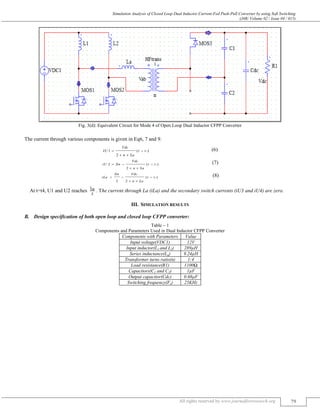
- 5. Simulation Analysis of Closed Loop Dual Inductor Current-Fed Push-Pull Converter by using Soft Switching (J4R/ Volume 02 / Issue 04 / 015) All rights reserved by www.journalforresearch.org 79 Fig. 3(d): Equivalent Circuit for Mode 4 of Open Loop Dual Inductor CFPP Converter The current through various components is given in Eq6, 7 and 9. )( 2 1 3tt Lan Vdc Ui (6) )( 2 2 3tt Lan Vdc IiniU (7) )( 22 3tt Lan VdcIin iLa (8) At t=t4, U1 and U2 reaches . The current through La (iLa) and the secondary switch currents (iU3 and iU4) are zero. III. SIMULATION RESULTS Design specification of both open loop and closed loop CFPP converter:B. Table – 1 Components and Parameters Used in Dual Inductor CFPP Converter Components with Parameters Value Input voltage(VDC1) 12V Input inductor(L1 and L2) 289µH Series inductance(La) 9.24µH Transformer turns ratio(n) 1:4 Load resistance(R1) 1100Ω Capacitors(C1 and C2) 1µF Output capacitor(Cdc) 0.68µF Switching frequency(Fs) 25KHz
- 6. Simulation Analysis of Closed Loop Dual Inductor Current-Fed Push-Pull Converter by using Soft Switching (J4R/ Volume 02 / Issue 04 / 015) All rights reserved by www.journalforresearch.org 80 Open Loop Simulation Circuit of Dual Inductor CFPP Converter:C. Fig. 4: Open Loop Dual Inductor CFPP Converter Simulation Circuit Simulation Waveforms of Open Loop Dual Inductor CFPP Converter:D. Voltages Waveforms:1) Fig. 4(a): Input, Primary and Output Voltages of Open Loop Dual Inductor CFPP Converter ZVS
- 7. Simulation Analysis of Closed Loop Dual Inductor Current-Fed Push-Pull Converter by using Soft Switching (J4R/ Volume 02 / Issue 04 / 015) All rights reserved by www.journalforresearch.org 81 Primary Switch Currents:2) Fig. 4(b): Switch U1, U2, La Currents of Open Loop Dual Inductor CFPP Converter Closed Loop CFPP Converter Simulation Circuit:E. Fig. 5: Closed Loop Simulation Circuit of Dual Inductor CFPP Converter ZCS
- 8. Simulation Analysis of Closed Loop Dual Inductor Current-Fed Push-Pull Converter by using Soft Switching (J4R/ Volume 02 / Issue 04 / 015) All rights reserved by www.journalforresearch.org 82 Simulation Waveforms of Closed Loop Dual Inductor CFPP Converter:F. Voltage Waveforms:3) Fig. 5(a): Input, Primary and Output Voltages of Closed Loop Dual Inductor CFPP Converter Primary Current Waveforms:4) Fig. 5(b): Switch U1, U2, La Currents of Closed Loop Dual Inductor CFPP Converter Analysis of Simulation Results:G. Open loop and closed loop simulation circuit of dual inductor CFPP converter is finished by utilizing SIMULINK. In this way the specification with their parts parameters utilized for both are arranged as appeared in Table1. Simulation of open loop dual inductor CFPP converter gives the output voltage of 520V as seen in simulation results. Primary voltage shows how ZVS is accomplished in the circuit as in Fig.4 (a) and the switch U2 current waveform in Fig.4 (b) indicates ZCS is accomplished in the circuit. Simulation of closed loop dual inductor CFPP converter is regulating output voltage of 350V as appeared in Fig. 5(a). IV. CONCLUSION Push-Pull DC-DC converters are best for smaller scale converter applications because of their better transformer usage contrasted with single ended topologies. The present encouraged these converters are utilized as a part of numerous applications like photograph voltaic (PV) power converters for boosting the yield voltage are proved in this project. Dual inductor CFPP converter is chosen, due to more preferences contrasted with single inductor CFPP, which is get proved after analyzing the circuit. Dual inductor CFPP converter is a new switching control strategy with voltage doubler circuit on secondary side. By detail analysis of equivalent modes of dual inductor CFPP converter, proved that the primary side switches are turned-ON with ZVS and turned-OFF with ZCS with the necessary of secondary side switches. Thus ZVS and ZCS (soft-switching) both are achieved, which helps in reducing switching loss and avoids the use of snubber circuits. And also dual inductor CFPP converter with voltage doubler circuit on secondary side proved the operation, by decreasing the components count. The designed dual inductor CFPP converter is implemented for a given specification. The converter is designed for input supply 12V, to get boosted voltage that is verified by simulation results of open loop CFPP converter. Primary side switches are
- 9. Simulation Analysis of Closed Loop Dual Inductor Current-Fed Push-Pull Converter by using Soft Switching (J4R/ Volume 02 / Issue 04 / 015) All rights reserved by www.journalforresearch.org 83 controlled by closed loop control topology. Closed loop results are provided such that, if there are any variations in the load, the CFPP converter is regulating the output voltage of 350V. Simulation of both open and closed loop CFPP converter is done by using SIMULINK. Controlling of 4 switches along with regulating for more voltage becomes difficult by closed loop strategy, which becomes the future work of the project. REFERENCES [1] W. Li, Y. Zhao, J. Wu, and X. He, “Interleaved high step-up converter with winding-cross-coupled inductors and voltage multiplier cells,” IEEE Trans. Power Electron., vol. 27, no. 1, pp. 133–143, 2012. [2] U. R. Prasanna, A. K. Rathore, and S. K. Mazumder, “Novel zero-current switching current-fed half-bridge isolated DC/DC converter for fuel cell based applications,’’ IEEE Trans. Ind. Appl., vol. 49, no. 4, pp. 1658–1668, 2013. [3] Radha Sree Krishns Moorthy and Akshay Rathore, “ Zero current switching current-fed parallel resonant push-pull(CFPRPP)converter”, International Power Electronics Conference, 978-1-4799-2705, 2014. [4] W. de A. Filho and I. Barbi, “A comparison between two current-fed push-pull DC-DC converters-analysis, design and experimentation,’’ in Proc. IEEE INTELEC, 1996, vol. 00, pp. 313–320. [5] K. Abarna, S. Divya and P. Rajeswari, “Soft-switching current-fed push-pull converter for PV application”, ARPN, vol. 10, No.8, ISSN 1819-6608, May 2015. [6] P. Sivaskthy and Dr. R. Anushya, “Closed loop residential photovoltaic power system with soft-switching push-pull front-end converter,” vol 3 Issue 6, ISSN 2321-919X, June 2015.